Table of Contents
Advertisement
Advertisement
Table of Contents

Related Manuals for USAVision UVS-ABL1300


Summary of Contents for USAVision UVS-ABL1300
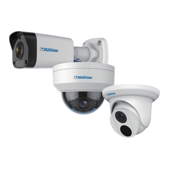
- Page 1 UVS-ABD1300, UVS-ABL1300, UVS-ADR1300 User's Manual Before attempting to connect or operate this product, please read these instructions carefully and save this manual for future use. UVS1300V101-A Available from A1 Security Cameras www.a1securitycameras.com email: sales@a1securitycameras.com...
- Page 2 USAVision. Every effort has been made to ensure that the information in this manual is accurate. USAVision, sys. makes no expressed or implied warranty of any kind and assumes no responsibility for errors or omissions. No liability is assumed for incidental or consequential damages arising from the use of the information or products contained herein.
- Page 3 Preface This Manual is designed for the following models and firmware versions: Model Model Number Firmware Version Eyeball Dome ABD1300 V1.01 Bullet IP Camera ABL1300 Mini Fixed Rugged IP Dome ADR1300 Available from A1 Security Cameras www.a1securitycameras.com email: sales@a1securitycameras.com...
-
Page 4: Table Of Contents
Contents Naming Definition..............iv Note for Connecting to GV-VMS / DVR / NVR ......v Note for Recording ..............vi Note for Installing Camera Outdoor ........vii Chapter 1 Introduction ............1 Key Features ......................2 1.2 Packing List ......................4 1.3 Optional Accessories ..................... 5 Chapter 2 Accessing the Camera.........6 2.1 Installing on a Network................... - Page 5 3.4.3 Privacy Mask....................40 3.5 Events ........................41 3.5.1 Motion Detection..................41 3.6 Storage ........................44 3.6.1 Storage.....................44 3.7 Security.........................46 3.7.1 User......................46 3.7.2 Network Security..................47 3.8 System........................49 3.8.1 Time ......................49 3.8.2 Maintenance .....................51 Chapter 4 Recording and Playback ........52 4.1 Recording ......................52 4.2 Playback from the Memory Card..............53 4.2.1 Recording Download ................55 Chapter 5 Advanced Applications ........56 5.1 Upgrading System Firmware.................56...
-
Page 6: Naming Definition
Naming Definition GV-System GeoVision Analog and Digital Video Recording Software. The GV- System also refers to Multicam System, GV-NVR System, GV- DVR System and GV-Hybrid DVR System at the same time GV-VMS GeoVision Video Management System for IP cameras. Available from A1 Security Cameras www.a1securitycameras.com email: sales@a1securitycameras.com... -
Page 7: Note For Connecting To Gv-Vms / Dvr / Nvr
Note for Connecting to GV-VMS / DVR / NVR The Eyeball Dome, Bullet IP Camera and Mini Fixed Rugged Dome are designed to work with and record on GV-VMS / DVR / NVR, a video management system. Once the cameras are connected to the GV-VMS / DVR / NVR, the resolution set on the GV-VMS / DVR / NVR will override the resolution set on the cameras’... -
Page 8: Note For Recording
Note for Recording Mind the following when using a memory card for recording: Recorded data on the memory card can be damaged or lost if the data are accessed while the camera is under physical shock, power interruption, memory card detachment or when the memory card reaches the end of its lifespan. -
Page 9: Note For Installing Camera Outdoor
Note for Installing Camera Outdoor When installing the camera outdoor, be sure that: The camera is set up above the junction box to prevent water from entering the camera along the cables. Any power, audio and I/O cables are waterproofed using waterproof silicon rubber or the like. - Page 10 Available from A1 Security Cameras www.a1securitycameras.com email: sales@a1securitycameras.com...
-
Page 11: Chapter 1 Introduction
Chapter 1 Introduction For ABD1300 The Eyeball Dome is an outdoor, network, camera equipped with an automatic IR-cut filter and an IR LED for day and night surveillance. The camera adheres to IP66 standards. For ABL1300 The Bullet Camera is an outdoor, network camera equipped with an automatic IR-cut filter and 2 IR LEDs for day and night surveillance. -
Page 12: Key Features
1.1 Key Features For ABD1300 1/3" progressive scan low lux CMOS sensor Min. illumination at 0.06 lux (B/W and color) Triple streams from H.264 and MJPEG Up to 30 fps at 1280 x 960 Intelligent IR ... - Page 13 Wide temperature tolerance (-35°C ~ 60°C / -31°F ~ 140°F) DC 12V / PoE (IEEE 802.3af) Wide Dynamic Range (WDR) Defog 3D noise reduction Motion detection Text overlay Privacy mask ONVIF (Profile S) conformant For ADR1300 ...
-
Page 14: Packing List
1.2 Packing List For ABD1300 Eyeball Dome Waterproof Rubber Set Screw x 2 Screw Anchor x 2 Drill Template Paster Software Download Guide Warranty Card For ABL1300 Bullet Camera Waterproof Rubber Set ... -
Page 15: Optional Accessories
Introduction 1.3 Optional Accessories Optional accessories can expand the capabilities and versatility of your cameras. Contact your dealer for more information. Model Number Name Details GV-Mount211 Dimensions: 233 x 126 x 126 Wall Box Mount mm (9.2” x 5” x 5”) Weight: 0.92 kg (2.0 lb) Only ABD1300 and ADR1300 support this accessory. -
Page 16: Chapter 2 Accessing The Camera
Chapter 2 Accessing the Camera Once installed, the camera is accessible on a network. Follow these steps to configure the network settings and access your surveillance images. 2.1 Installing on a Network These instructions describe the basic connections to install the camera on the network. 1. Using a standard network cable, connect the camera to your network. -
Page 17: Checking The Dynamic Ip Address
2.1.1 Checking the Dynamic IP Address Follow the steps below to look up the IP address and access the Web interface. Download and install the GV-IP Device Utility program from http://www.geovision.com.tw/english/5_8.asp Note: The PC installed with GV-IP Device Utility must be under the same LAN with the camera you wish to configure. - Page 18 The login page appears. Figure 2-3 For the first time accessing the Web interface, download and install the plug-in. Type the default ID and password admin and click Login to login. Available from A1 Security Cameras www.a1securitycameras.com email: sales@a1securitycameras.com...
-
Page 19: Assigning An Ip Address
2.1.2 Assigning an IP Address To assign a new static IP address, log in the Web interface to access the network setting page. Note: If your router does not support DHCP, the default IP address will be 192.168.0.10. In this case, it is strongly suggested that you modify the IP address to avoid the IP address conflict with other GV-IP devices on the same LAN. - Page 20 Enter the IP address, subnet mask, and default gateway address. Make sure that the IP address of the camera is unique in the network. Click Save. Note: When you are changing the network segment through the Web interface or the GV- IP Device Utility (V8.7.0.0), it is required that you change the default gateway too to complete the IP address change successfully.
-
Page 21: Accessing Live View
2.2 Accessing Live View After logging in to your camera, you will see the Home page as shown below: Figure 2-5 Available from A1 Security Cameras www.a1securitycameras.com email: sales@a1securitycameras.com... -
Page 22: The Live View Window
2.2.1 The Live View Window Figure 2-6 No. Name Function Set the display ratio of the image. Scale: display images by 16:9. Proportional Stretch: display images by window size. Original: display images in its original size. Select a live video stream: main stream, sub stream or third Live Stream stream. - Page 23 Display packet loss rate and bit rate information in the bottom. Note: The paths for saving snapshots and local recordings are set in System Configuration. The buttons (No. 9 and No. 10) will appear on the floating toolbar after you move the mouse cursor on a live view window.
-
Page 24: Digital Zoom
2.2.1.1 Digital Zoom To use the digital zoom function, follow these steps: 1. Click (No. 8, Figure 2-6) on the toolbar. 2. Click and hold the mouse button, and then drag from the top down to specify an area. 3. To restore the original image size, click in the enlarged area, or drag from the bottom up. 4. -
Page 25: Chapter 3 Administrator Mode
Chapter 3 Administrator Mode The Administrator can access and configure your camera through the network. Click Setup at the top of the Web interface to access the following seven configuration tabs: Common, Network, Video, Image, Events, Storage, Security and System. Figure 3-1 Available from A1 Security Cameras www.a1securitycameras.com email: sales@a1securitycameras.com... - Page 26 List of Options See the table below for the settings available on the Web interface. Find the topic of interest by referring to the section number prefixed to each option. The configuration tabs and settings may vary with available models. 3.1.1 Basic Info 3.1 Common 3.1.2 Local Settings...
-
Page 27: Common
3.1 Common Under the Common tab, the Administrator can find the general settings for the camera, as well as shortcuts to the following setting pages. Ethernet: See 3.2.1 Network for details. Time: See 3.8.1 Time for details. OSD: See 3.4.2 OSD for details ... -
Page 28: Local Settings
3.1.2 Local Settings You can set local parameters for your PCs. Figure 3-3 [Video Param] Processing Mode Real Time Prior: Select this if the network is in good condition. Fluent Prior: Select this if you want short time lag for live video. ... - Page 29 [Recording and Snapshot] Recording Subsection By Time: Set a maximum time length of each recording file. If you select 5 minutes, a 30-minute event will be chopped into six 5-minute event files. Subsection by Size: Set a maximum size limit of each recording file. ...
-
Page 30: Network
3.2 Network The network section allows you to configure the network settings, modify ports, configure FTP server, and set up e-mail for notification. 3.2.1 Network Figure 3-4 IPv4: Select Static IP or DHCP according to your network environment. Static IP address: Assign a static IP or fixed IP to the camera. Type the camera’s IP address, Subnet Mask, Router/Gateway, Preferred DNS server and Alternate DNS server. - Page 31 DHCP: The network environment has a DHCP server which will automatically assign a dynamic IP address to the camera. You can look up the current IP address using GV-IP Device Utility. IPv6: Type the camera’s IPv6 Address and Default Gateway. Optionally change the Prefix Length according to your network settings.
-
Page 32: Dns
3.2.2 DNS The configuration of DNS (Domain Name System) server is applicable when the device is accessed by domain name. For details, see IPv4, 3.2.1 Network. Figure 3-5 Available from A1 Security Cameras www.a1securitycameras.com email: sales@a1securitycameras.com... -
Page 33: Port
3.2.3 Port Port You can modify the default HTTP port, HTTPS port and RTSP port if necessary. Figure 3-6 Port Mapping This function can automatically forward and open certain ports on your router, allowing connection to your camera from the Internet. Figure 3-7 1. - Page 34 3. If you select Manual, configure external ports. External IP is applied to the camera automatically. If the configured port is occupied, the Status will show inactive. 4. Click Save. Note: For this function, your router needs to support port forwarding. Available from A1 Security Cameras www.a1securitycameras.com email: sales@a1securitycameras.com...
-
Page 35: Ftp
3.2.4 FTP After the configuration of FTP, you will be able to upload snapshots from the camera to the specified FTP server. Figure 3-8 1. Type the Server IP address. 2. Change the Port No. of the FTP server if needed. 3. - Page 36 (2) The snapshots will be stored in the “cover” folder as shown below. If the number of images in Overwrite At (Image) is 10 for example, the file name of the snapshots will be listed from 1 to 10. Figure 3-9 Unselecting Overwrite Storage (1) Select items from the Save To Root Directory drop-down list to create the snapshot storage path;...
-
Page 37: E-Mail
3.2.5 E-mail After the configuration of E-mail, you will be able to send messages to the specified E-mail address when alarms are triggered. Figure 3-11 [Sender] 1. Type the Name and Address of the sender. 2. Type the SMTP Server. 3. Type the SMTP Port number. -
Page 38: Video
3.3 Video This section allows you to configure the three video streams. 3.3.1 Video You can set video parameters that your camera supports. You may also enable the sub- stream and third stream as needed. Figure 3-12 Image Collection Mode: Sets the maximum resolution and frame rate. ... - Page 39 I Frame Interval: Set the number of frames between each I frame (key frame). This option is only available when H.264 is selected for codec. Smoothing: Set the extent of smoothing. Choosing Clear means disabling Smoothing. Moving the slider toward Smooth increases the level of smoothing but will affect image quality.
-
Page 40: Snapshot
3.3.2 Snapshot Using the Snapshot function, when an alarm is triggered, the camera will automatically upload the captured snapshots to the FTP server or send snapshots to the specified e-mail address. Figure 3-13 Enable Snapshot. Select Resolution. Choose the Image Quality. Choose the Number (of snapshot) to Capture upon alarm trigger. -
Page 41: Media Stream
3.3.3 Media Stream Media Stream By configuring media stream, you can set the camera to transmit code streams by UDP or TCP protocol to a specified IP address and port number. The settings can be saved and take effects after the camera is restarted. Figure 3-14 1. Click + and then select a type in the Stream Profile. - Page 42 RTSP Multicast Address After an RTSP multicast address is configured, the third-party player can request the RTSP multicast media stream from the camera through the RTP protocol. Figure 3-15 1. Type the Multicast Address (224.0.0.0 to 239.255.255.255) and Port number (0 to 65535).
-
Page 43: Image
3.4 Image This section introduces the Image Settings, On-screen Display, and Privacy Mask. 3.4.1 Image This page allows you to adjust image settings such as brightness, exposure, IR illumination and white balance. Figure 3-16 [Scene] Current: Indicates the scene that is being used. Screen Name: When you select a scene, the corresponding image parameters are ... - Page 44 Figure 3-17 [Image Enhancement] Brightness: Adjust the degree of brightness of the image. Saturation: Adjust the amount of a hue contained in a color. Contrast: Set the degree of difference between the blackest pixel and the whitest pixel. ...
- Page 45 Figure 3-18 [Exposure] Exposure Mode: Select the correct exposure mode to achieve the desired exposure effect. The default setting is Outdoor. Shutter (s): The length of time that allows light to enter into the lens. You can set a shutter speed when Exposure Mode is set to Manual.
- Page 46 Compensation: Adjust the compensation value as required to achieve the desired effects. You can set this parameter only when Exposure Mode is not set to Manual. Metering Control: Set the way the camera measures the intensity of light. You can only set this parameter when Exposure Mode is not set to Manual.
- Page 47 Figure 3-19 [Smart Illumination] Smart Illumination: Select Enable to adjust the IR illumination settings. Control Mode: Global Mode: Adjust IR illumination and exposure to achieve balanced image effects. Some areas might be overexposed if you select this option. This option is recommended if monitored range and image brightness are your first priority.
- Page 48 Figure 3-20 [White Balance] White Balance: Adjust the red or blue offset of the image. Auto: Adjust the red and blue offset automatically according to the light condition (the color tends to be blue). Outdoor: It is recommended for the outdoor scenes with a wide range of the color temperature variation.
-
Page 49: Osd
3.4.2 OSD On Screen Display (OSD) is the text displayed on the screen with video images and may include time and other customized contents. Figure 3-22 1. Enable a No. to select an area #, and then click Overlay OSD Content to select the content to display on screen. -
Page 50: Privacy Mask
3.4.3 Privacy Mask On certain occasions, you may need to set a mask area to block out parts of the camera image to protect privacy, for example, the keyboard of an ATM machine. When PTZ changes its position or zooms, the Privacy Mask will be adjusted accordingly to protect the area all along. -
Page 51: Events
3.5 Events You can set the camera to generate an alarm upon motion detection. 3.5.1 Motion Detection Motion detection is used to generate an alarm whenever movement occurs in the specified area. Figure 3-24 1. In the Detection Area, click to add a new detection area. - Page 52 3. You can use the following functions to reduce false alarm. Sensitivity: Move the slider to the right to increase detection sensitivity. Object Size: When the extent of motion within the detection area exceeds the set object size, motion detection alarm will be triggered. [Alarm Parameters] ...
- Page 53 [Enable Plan] Select this option to set the start and end times during which motion detection alarm is enabled. You can directly drag the mouse to draw a plan or click Edit to edit time periods in the table. You can set up to four periods for each day, and the time periods cannot overlap. The camera reports alarms during the specified period(s) only.
-
Page 54: Storage
3.6 Storage This section allows you to configure memory card settings. 3.6.1 Storage Note this function is only for ADR1300. After inserting a memory card to the camera, you need to format the memory card using the Format button on this page. Figure 3-26 The following storage settings are available. - Page 55 When Storage Full: Overwrite: If there is no free space in the memory card, new data will overwrite the existing data repeatedly. Stop: If there is no free space in the memory card, new data will not be saved to the memory card.
-
Page 56: Security
3.7 Security This section allows you to create user accounts and set the network security settings. 3.7.1 User There are two types of accounts: Administrator and Common User. Administrator: The default name of the administrator is admin, which cannot be modified. -
Page 57: Network Security
3.7.2 Network Security There are four types of network security settings: HTTPS, RTSP Authentication, ARP Binding and IP Address Filtering. HTTPS You can enable the Hypertext Transfer Protocol Secure (HTTPS) settings to access the camera through a secure protocol. Click Enable and click Save. Figure 3-28 RTSP Authentication RTSP (Real Time Streaming Protocol) is an application layer protocol for transmitting video. - Page 58 ARP Binding This function can protect the camera from ARP attacks. When the camera visits an IP of another network segment via a gateway, it can only communicate with the MAC address binding to the gateway address in the same segment. Figure 3-30 1.
-
Page 59: System
3.8 System This section allows you to set the camera time, and update the firmware. 3.8.1 Time You can use the following methods to adjust the system time of your camera. Figure 3-32 To manually set a time or synchronize with the computer time: Select Sync with Latest Server Time from the Sync Mode drop-down list. - Page 60 To adjust the camera’s time for daylight saving time: Click the DST tab at the top. Figure 3-34 Select Enable DST. Set a Start Time and End Time for the daylight saving time. Select a time period for DST Bias. Click Save.
-
Page 61: Maintenance
3.8.2 Maintenance This section allows you to upgrade firmware, restart the camera, and backup/import camera configurations. Figure 3-35 [Software Upgrade] For detailed instructions, refer to 5.1 Upgrading System Firmware and 5.1.1 Using the Web Interface. [Device Restart] Click Restart to restart the device after you confirm the operation. [Config Management] Export the current configurations of the camera and save them to the PC or an external storage medium. -
Page 62: Chapter 4 Recording And Playback
Chapter 4 Recording and Playback Note this function is only for ADR1300. The camera can record video and audio directly to the memory card. Note: See Note for Recording at the beginning of the manual. 4.1 Recording To configure the recording function, refer to the following sections ... -
Page 63: Playback From The Memory Card
4.2 Playback from the Memory Card You can play back the files recorded at the memory card of the camera from the Web interface. Click Playback at the top. This page appears. Figure 4-1 On the right, select a date and click Query. Figure 4-2 Available from A1 Security Cameras www.a1securitycameras.com email: sales@a1securitycameras.com... - Page 64 Double-click a search result to play back the recorded file. Figure 4-3 The following functions are available: Snapshot : Click to capture a snapshot of the recorded video. Digital Zoom : Click the icon and draw a box on the camera view to digitally zoom Available from A1 Security Cameras www.a1securitycameras.com email: sales@a1securitycameras.com...
-
Page 65: Recording Download
Recording and Playback 4.2.1 Recording Download You can search and download the recorded videos stored in the memory card. Click Recording Download on the Playback page. Select a time period to search for video, and click Search. The search results are shown. -
Page 66: Chapter 5 Advanced Applications
Chapter 5 Advanced Applications This chapter introduces more advanced applications. 5.1 Upgrading System Firmware We periodically release the updated firmware on the website. The new firmware can be simply loaded into the camera using the Web interface or the GV-IP Device Utility. Important Notes before You Start Before you start updating the firmware, please read these important notes: 1. If you use the GV-IP Device Utility for firmware upgrade, the computer used to upgrade... -
Page 67: Using The Web Interface
5.1.1 Using the Web Interface Log into the Web interface and follow the steps below to update the firmware. 1. At the top, click Setup. 2. In the left menu, select System and select Maintenance. This page appears. Figure 5-1 3. Click the Browse button to locate the firmware file (.zip) saved at your local computer. -
Page 68: Using The Gv-Ip Device Utility
5.1.2 Using the GV-IP Device Utility You can upgrade the camera firmware using the GV-IP Device Utility. Note the computer used to upgrade firmware must be under the same network of the camera. 1. Download GV-IP Device Utility from http://www.geovision.com.tw/english/5_8.asp Then follow the onscreen instructions to install the program. - Page 69 6. Click the Browse button to locate the firmware file (.zip) saved at your local computer. 7. Click Upgrade to start upgrading the firmware. Available from A1 Security Cameras www.a1securitycameras.com email: sales@a1securitycameras.com...
-
Page 70: Restoring To Factory Default Settings
5.2 Restoring to Factory Default Settings You can restore the camera to factory default settings using the Web interface or directly on the camera. Note: There is no default button on ABD1300 and ADR1300. 5.2.1 Using the Web Interface 1. At the top, click Setup. 2. -
Page 71: Directly On The Camera
Advanced Applications 5.2.2 Directly on the Camera Note this function is only for ABL1300. Press and hold the default button for at least 15 seconds to restore to factory default settings. Figure 5-5 Available from A1 Security Cameras www.a1securitycameras.com email: sales@a1securitycameras.com... -
Page 72: Chapter 6 Dvr Configurations
Chapter 6 DVR Configurations The GV-VMS / DVR / NVR provide complete video management, such as video viewing, recording, playback, alert settings, and almost every feature of the system. The integration specifications are listed below: The compatible GV-VMS / DVR / NVR versions are listed below: Camera Model Compatible GV-System Compatible GV-VMS... -
Page 73: Setting Up Ip Cameras On Gv-System
6.1 Setting Up IP Cameras on GV-System To set up the camera on the GV-System, follow these steps: On the main screen, click the Configure button, select System Configure, select Camera Install and click IP Camera Install. This dialog box appears. Figure 6-1 To automatically set up the camera, click Scan Camera to detect any camera on the LAN. - Page 74 Click OK. This dialog box appears. Figure 6-3 Click OK. The IP camera is added to the connection list. Click the listed camera and select Display position to map the IP camera to a channel on the GV-System. Figure 6-4 The Statue column should display “Connected”.
-
Page 75: Customizing The Basic Settings On Gv-System
6.1.1 Customizing the Basic Settings on GV-System After the camera is connected and assigned with a display position, you can configure the camera’s settings such as frame rate, codec type and resolution. Right-click the desired camera to see the following list of options: Figure 6-5 Network Time Out: When network disconnection exceeds the specified time period, the ... -
Page 76: Setting Up Ip Cameras On Gv-Vms
6.2 Setting Up IP Cameras on GV-VMS Follow the steps below to manually connect your camera to GV-VMS. 1. To access the IP Device Setup page, click Home , select Toolbar , click Configure and select Camera Install. Figure 6-6 2. Click Automatic Setup 3. Double-click the camera and type the user name and password of the camera. - Page 77 DVR Configurations 4. Click OK. This dialog box appears. Figure 6-8 5. Click OK to add the camera to the list. 6. To connect the added camera, click the box besides the ID column. Upon successful connection, the Status icon shows green, with the video resolution and bitrate being displayed in the correspondent columns.
-
Page 78: Appendix
Appendix A. RTSP Protocol Support The camera can support RTSP protocol for both video and audio streaming. If you are using Quick Time player, use the following RTSP command: rtsp://<IP of the camera>:554/<CH No.>.sdp For example, rtsp://192.168.3.111:554/CH001.sdp If you are using VLC player, use the following RTSP command: rtsp://<ID>:<Password>@<IP of the camera>:554/<CH No.>.sdp For example, rtsp://admin:admin@192.168.3.111:554/CH001.sdp If you use the VLC, and if authentication is not required, enter:... -
Page 79: Optional Installation For Abd1300
B. Optional Installation for ABD1300 You can optionally purchase GV-Mount211 or GV-Mount212 for Wall Box Mount. Follow the instructions below. GV-Mount211 Figure B-1 Available from A1 Security Cameras www.a1securitycameras.com email: sales@a1securitycameras.com... - Page 80 GV-Mount211 Packing List GV-Mount211 Wall Mount Bracket Long Screw x 4 Short Screw x 3 Screw Anchor x 5 Plastic PG21 Conduit Connector Drill Template Paster 1. Unscrew the bracket. Figure B-2 Available from A1 Security Cameras www.a1securitycameras.com email: sales@a1securitycameras.com...
- Page 81 2. Loosen the indicated area by turning it anticlockwise. Figure B-3 3. Stick the drill template paster to the wall with the arrow pointing up. 4. Drill 4 holes according to the sticker and insert the 4 screw anchors to the 4 holes. 5.
- Page 82 6. Remove the bottom ring by turning it anticlockwise. Figure B-5 7. Thread the network and power wires through the camera housing. 8. Secure the camera to the wall box mount with 3 short screws. Figure B-6 Available from A1 Security Cameras www.a1securitycameras.com email: sales@a1securitycameras.com...
- Page 83 9. Thread the Ethernet cable through the PG21 conduit connector and the camera housing as shown in No. 9, Figure B-7. 10. Rotate the plastic ring to secure the conduit connector to the camera housing. Screw in the cap as shown in No. 10, Figure B-7. 11.
- Page 84 GV-Mount212 GV-Mount212 Figure B-9 GV-Mount212 Packing List GV-Mount212 Wall Box Mount Long Screw x 3 Short Screw x 3 Screw Anchor x 3 Available from A1 Security Cameras www.a1securitycameras.com email: sales@a1securitycameras.com...
- Page 85 Standard Installation Attach the wall box to the wall and use a marker to mark the location for the center socket and the screws. Make sure the knob points down. Figure B-10 Drill 3 holes according to the screw location. Then, drill a bigger hole at the center socket location for the Ethernet cable.
- Page 86 Thread the Ethernet cable through the center socket and waterproof the Ethernet cable. For details, see E.Waterproofing the Cable. Figure B-13 Fit the cable into the wall box. Before securing the camera, make sure the indicated area fits to the designated location. Figure B-14 Secure the camera by locking 2 short screws to the indicated position.
- Page 87 Note: In addition to the Standard Installation, you can also choose to run the Ethernet cable through a corrugated tube. To do this, you will have to purchase your own conduit connector and corrugated tube. 3/4” NPS is the recommended type of connector.
-
Page 88: Optional Installation For Adr1300
C. Optional Installation for ADR1300 You can optionally purchase GV-Mount211 for Wall Bracket Mount. Follow the instructions below. Figure C-1 Available from A1 Security Cameras www.a1securitycameras.com email: sales@a1securitycameras.com... - Page 89 GV-Mount 211 Packing List For details, see Appendix B. Optional Installation for ABD1300. 1. Unscrew the bracket. Figure C-2 2. Loosen the indicated area by turning it anticlockwise. Figure C-3 3. Stick the drill template paster to the wall with the arrow pointing up. 4.
- Page 90 6. Unscrew the transparent dome cover with the supplied torx wrench. Figure C-5 7. Optionally insert a micro SD card into the micro SD card slot to use the local storage function. Figure C-6 Available from A1 Security Cameras www.a1securitycameras.com email: sales@a1securitycameras.com...
- Page 91 8. Thread the network and power wires through the wall mount bracket. 9. Secure the camera to the wall mount bracket with 2 short screws. Figure C-7 10. Secure the transparent dome cover with the supplied torx wrench. Figure C-8 Available from A1 Security Cameras www.a1securitycameras.com email: sales@a1securitycameras.com...
- Page 92 11. Thread the Ethernet cable through the PG21 conduit connector and the power box as shown in No. 9, Figure C-9. 12. Rotate the plastic ring to secure the conduit connector to the power box. Screw in the cap as shown in No. 10, Figure C-9. 13.
-
Page 93: Optional Installation For Abl1300
D. Optional Installation for ABL1300 You can optionally purchase GV-Mount502 for Wall Box Mount. Follow the instructions below. Figure D-1 Available from A1 Security Cameras www.a1securitycameras.com email: sales@a1securitycameras.com... - Page 94 GV-Mount502 Packing List GV-Mount502 Wall Mount Box M3 25 mm Screw x 4 M3 12 mm Screw x 4 Screw Anchor x 4 Plastic PG21 Conduit Connector 1. Unscrew the box cover. Figure D-2 Available from A1 Security Cameras www.a1securitycameras.com email: sales@a1securitycameras.com...
- Page 95 2. Loosen the indicated area by turning it anticlockwise. Figure D-3 3. Attach the box to the wall with the arrow pointing up and use a marker to mark 4 dots. Figure D-4 4. Drill 4 holes according to the marks and insert the 4 screw anchors to the 4 holes. Available from A1 Security Cameras www.a1securitycameras.com email: sales@a1securitycameras.com...
- Page 96 5. Secure the power box to the wall with four M3 25 mm screws. Figure D-5 6. Thread the network and power wires through the wall mount box cover. 7. Secure the camera to the wall mount box cover with 4 M3 12 mm screws. Figure D-6 Available from A1 Security Cameras www.a1securitycameras.com email: sales@a1securitycameras.com...
- Page 97 Appendix 8. Thread the Ethernet cable through the PG21 conduit connector and the wall mount box as shown in No. 9, Figure D-7. 9. Rotate the plastic ring to secure the conduit connector to the wall mount box. Screw in the cap as shown in No.
-
Page 98: Waterproofing The Cable
E. Waterproofing the Cable Waterproof the Ethernet cable by using the supplied waterproof rubber set. 1. Attach the seal ring to the RJ-45 plug. Seal ring Figure E-1 2. Insert the waterproof components through the Ethernet cable as shown below. Insert in order Figure E-2 3. - Page 99 Appendix 4. Insert the cable into the RJ-45 plug and screw the waterproof bolt in. Figure E-4 5. Screw in the waterproof bolt lid. Bolt lid Figure E-5 6. Finish the waterproof Installation. Figure E-6 Available from A1 Security Cameras www.a1securitycameras.com email: sales@a1securitycameras.com...
Need help?
Do you have a question about the UVS-ABL1300 and is the answer not in the manual?
Questions and answers