
Related Manuals for P1PE P2000i


Summary of Contents for P1PE P2000i
- Page 1 P1PE INVERTER GENERATOR P2000i P2000iS P2500i P2500iS User Manual FOR YOUR SAFETY You must read and understand this manual before use. Keep this manual for future reference.
-
Page 2: Table Of Contents
Introduction ................................3 Parts Ordering / Customer Service....................... 3 Safety Rules ................................4 Safety Symbols ............................. 4 Safety Instructions ............................4 Features .................................. 7 Control Panel Functions ............................8 ON/OFF Start Switch and Choke......................... 8 Indicator Lights ............................. 8 DC Protector .............................. -
Page 3: Introduction
. It is designed to supply electrical power to operate tools, appliances, camping equipment, lighting, or serve as a back up power source during power outages. Generator specification MODEL P2000i P2000iS P2500i P2500iS 110V,120V,220V,230V,240V Rated AC Voltage(V) -
Page 4: Safety Rules
SAFETY RULES Safety Symbols Indicates a potentially hazardous WARNING! situation which could result in serious injury or death if not avoided. CAUTION! Toxic Fumes Risk of explosion Risk of electric shock Hot surface Safety Instructions the user must understand and follow all manual instructions and use common sense. Read and understand this manual in its entirety before operating this generator. - Page 5 SAFETY RULES Never exceed generators wattage / amperage capacity. This could damage the generator WARNING! and / or connected electrical devices. • Check operating voltage and frequency requirements of all electrical devices prior to plugging them into the generator. Never start or stop engine with electrical devices plugged in to the receptacles. Failure to WARNING! do so could damage the generator and / or connected electrical devices.
- Page 6 SAFETY RULES This generator produces a very high voltage which could result in burn or WARNING! electrocution causing serious injury or death. • Never handle the generator, electronic devices, or any cord while standing in water, while barefoot, or when hands or feet are wet.
-
Page 7: Features
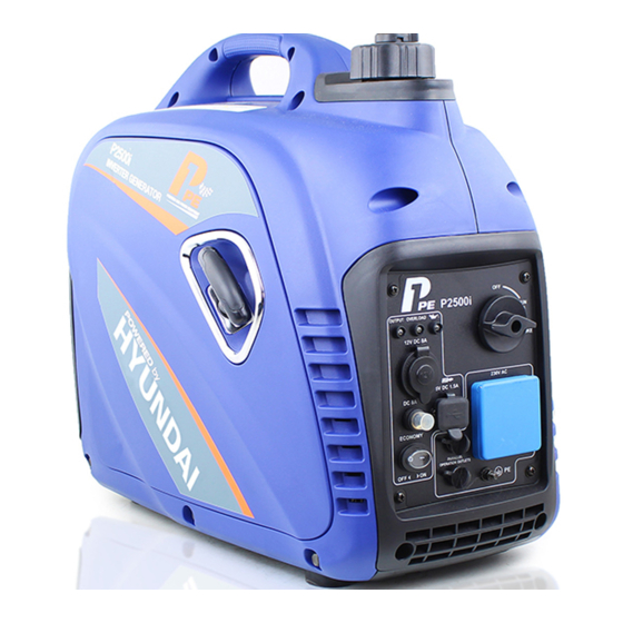
FEATURES P1 - 120V AC Outlet A - Spark Plug Cover I - Control Panel Q - Parallel Outlets B - Spark Arrestor J - Oil Warning Light R - Ground Terminal K - Overload Indicator Light S - 12V DC Port L - AC Pilot Light D - Outer Casing (Side Panel) M - 3 in 1 Start Switch (RUN / OFF and Choke) -
Page 8: Control Panel Functions
CONTROL PANEL FUNCTIONS ON/OFF Start Switch and Choke Start Switch “OFF” When the Start Switch is in the “OFF” position the fuel valve is switched off and the engine will not run. Start Switch “CHOKE” When the Start Switch is in the “CHOKE” position the fuel valve is switched on and the engine can be started. -
Page 9: Dc Protector
CONTROL PANEL FUNCTIONS AC Pilot Indicator Light The green AC Pilot Indicator Light comes on when the engine starts and generates power. Oil Warning Overload AC Pilot Indicator Indicator Indicator DC Circuit Breaker When the DC Circuit Breaker is in the “ON” position, the generator is able to supply power to connected electronic devices. When the DC Circuit Breaker is in the “OFF”... -
Page 10: Fuel Cap Air Vent
CONTROL PANEL FUNCTIONS Fuel Cap Turn counterclockwise to remove the fuel cap Fuel Cap Air Vent The fuel cap is equipped with an air vent to stop fuel from flowing to the carburetor. The Air Vent must be in the “ON” position to allow fuel to flow so that the engine can run. -
Page 11: Assembly
ASSEMBLY Connecting Generator to an Electrical System • If connecting generator to a building’s electrical system for standby power, The power from the generator must be isolated from the circuit breaker or alternative power source. The connection must comply with all electrical codes and applicable laws. -
Page 12: Adding / Checking Oil
ASSEMBLY • Place generator on a level surface. • Remove screws and then remove the outer casing cover. (You must remove the spark plug cover to push the side panel off from the inside) • Remove the crankcase dipstick. • Insert a funnel into the crankcase dipstick hole and carefully add the specified amount of 4-Cycle engine oil (SAE 10W- 30) to empty reservoir until or oil reaches the outer edge of the oil fill hole (crankcase dipstick hole). -
Page 13: Operation
OPERATION Grounding the Generator To avoid electrocution, this generator must be properly grounded prior to use. For instructions see Control Panel Functions pg. 10. Standard Atmospheric Conditions Ambient Temperature: 77ºF (25ºC) Barometric Pressure: 100kPa Relative Humidity: 30% Generator output will vary due to changes in temperature, altitude, and humidity. If the temperature, humidity, or altitude are higher than standard atmospheric conditions, the generator’s output will be reduced. -
Page 14: How To Stop Engine
OPERATION How to Stop Engine • Turn the ECO switch to the “OFF” position. • Disconnect any electronic device. All loads MUST be disconnect from the generator. Never start or stop the engine with electrical devices plugged in to the receptacles. •... -
Page 15: Charging A 12 Volt Battery
OPERATION Charging a 12 Volt Battery This generator can be used to charge a 12 volt automotive or storage battery by taking the following steps: ONLY level is low. Never add tap water. 1. Use a wire brush to clean battery terminals if corroded. 2. -
Page 16: Ac Parallel Operation
OPERATION AC Parallel Operation The D2000iS generator has two models that are compatible with each other (Standard and Companion). It is possible to connect two D2000iS generators to each other, using a parallel cable kit. • Connect PARALLEL OPERATION CABLES to two D2000iS generators according to the instructions provided with the cable kit. -
Page 17: Don't Overload Generator
OPERATION Don’t Overload Generator Make sure you can supply enough rated watts for all electronic devices connected to the generator. Rated watts refer to the power a generator must supply to keep a device running. Surge watts refer to the power a generator must supply to start an electronic device. -
Page 18: Maintenance
MAINTENANCE Regular maintenance will extend the life of this generator and improve its performance. The warranty does not cover items that result from operator negligence, misuse, or abuse. To receive full value from the warranty, operator must maintain the generator as instructed in this manual, including proper storage. Before inspecting or servicing this machine, make sure the engine is off and no parts are WARNING! moving. -
Page 19: Checking Spark Plug
MAINTENANCE Checking Spark Plug • Remove cap. Then remove spark plug cap. • Disconnect the spark plug wire from the spark plug. • Before removing the spark plug, clean the area around its base to prevent debris from entering the engine. •... -
Page 20: Changing Oil
MAINTENANCE Changing Oil • Place generator on a level surface. • Run the generator for several minutes until the engine is warm. Turn off generator. • Remove screws, then remove outer casing. • Remove the crankcase dipstick. • Place an oil pan underneath the engine. Tilt generator to collect used oil. Allow oil to drain completely. •... -
Page 21: How To Clean Air Filter
MAINTENANCE Air Filter • To clean, remove the screws then remove outer casing. • • Remove the foam element. • Wash the foam element in solvent and let dry. • Pour a small amount of oil on the foam element then squeeze out, but do not wring out, excess oil. -
Page 22: How To Clean Fuel Filter
MAINTENANCE Fuel Tank Filter • • • • • Install fuel cap. Fuel Filter • To clean, remove screws, remove outer casing, and drain fuel. • Lift and hold onto the clamp, then remove hose from tank. • • • •... - Page 23 MAINTENANCE How to drain fuel • Turn the 3 in 1 switch to the “OFF” position. • • Use a siphon to transfer gasoline from generator into a gasoline approved container. • Wipe up any spilled fuel with a clean rag. •...
-
Page 24: Troubleshooting
TROUBLESHOOTING Problem Cause Solution 1. DC Circuit Breaker is “OFF” 1. Turn DC Circuit Breaker “ON” Generator is running, but does not supply power. 2. Green AC Pilot Light Indicator is off. 2. Stop engine and restart. 3. Poor connection 3. -
Page 25: Recycling & Product Disposal
RECYCLING & PRODUCT DISPOSAL • We do not offer a takeback scheme for the recovery of Waste Electrical Electronic Equipment (WEEE) & Batteries. Instead the responsibility to dispose of WEEE and or Batteries is passed onto you by us. So when it becomes necessary to dispose of your machine, you must take it to your local Civic Amenity Site. For further information please contact your local Authority for disposal advice. -
Page 26: Declaration Of Conformity
DECLARATION OF CONFORMITY Genpower Ltd confirms that these P1PE products conform to the following CE Directives. 97/68/EC Non Road Mobile Machinery Directive 2000/14/EC Outdoor Noise Directive 2004/108/EC Electro Magnetic Compatibility Device 2006/42/EC Machinery Directive P2000i / P2000iS P2500i / P2500iS Inverter Generator P2000i / P2000iS –... -
Page 27: Contact Details
CONTACT DETAILS Postal Address Genpower Limited London Road, Pembroke Dock, Pembrokeshire. SA72 4RW. UK Telephone +44 (0) 1646 687880 +44 (0) 1646 686198 Website www.p1pe.co.uk WARRANTY To register your machine for the manufacturer’s warranty, please visit: http://www.p1pe.co.uk/warranty... - Page 28 P1PE – Position One Power Equipment Isaac Way, Pembroke Dock, Pembrokeshire, SA72 4RW www.p1pe.co.uk www.p1pe.co.uk...
Need help?
Do you have a question about the P2000i and is the answer not in the manual?
Questions and answers