
Related Manuals for SafetyLink X-Rail


Summary of Contents for SafetyLink X-Rail
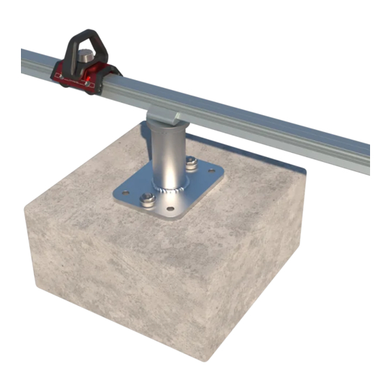
- Page 1 Horizontal Rigid anchor line SafetyLink ® InStallation and Use Innovative Fall Protection Figure 1 INSTRUCTION: XRAIL-INST-SURFACE-MOUNT REVISION: 2.0...
-
Page 2: Specification
SafetyLink Pty Ltd. Specification Description The SafetyLink X-Rail is a Rigid Anchor Line suitable for use as part of a personal fall protection system. The X-Rail offers a horizontal Rigid Anchor Line with one or multiple Mobile Anchor Points for attaching to. - Page 3 Components Figure 2 RAIL LENGTH 3M CROSS PLATE RAIL JOIN KIT CONCEALED XRAIL-TR-102-3M XRAIL-TR-210 XRAIL-TR-005 RAIL END CAP SHUTTLE STOP SHUTTLE XRAIL-TR-213 XRAIL-TR-006 XRAIL-TR-014 90° CORNER 45° CORNER RAIL JOIN DOWEL XRAIL-TR-104 XRAIL-TR-107 XRAIL-TR-212 RAIL SCREW DRILL ON-SITE FIXTURE RAIL DRILL BIT XRAIL-TR-907(OTS) XRAIL-TR-402 XRAIL-TR-401...
-
Page 4: Installation
It is important to consider the location of corners when designing your system to ensure the rails and corner fastening detail can match the detail in Section 4 of this instruction. The X-Rail Rigid Anchor Line shall be installed on an angle no greater than 5º. Figure 3 ... - Page 5 3.1.3 Intermediate Fixing Spacing Exact intermediate fixing spacings are determined by the roof sheeting. The below are the maximum allowable distances. On a straight section of rail designed for fall arrest, intermediate fixing shall be installed at a distance not greater than 1m. On a straight section of rail designed for abseil, intermediate fixings shall be installed at a distance not greater than 0.6m.
- Page 6 Figure 7 Fixings 3.2.1 Rivets All rivets used to connect the rail profile to the roof sheeting, rail profile to the Cross plate or Cross plate to the roof sheeting shall be; 8mm Tri fold aluminium rivets measuring 27.7mm long with a grip range of 1.0-9.5mm. Drill size 7.8-8.2mm. ⚠...
- Page 7 KingZip400 40Nm 16Nm Fasteners All X-Rail Fasteners are M10 socket head cap screws. All fasteners shall be tightened to 40Nm with a 6mm hex wrench. ⚠ All bolt threads must be applied with Loctite 243 thread-locker or equivalent prior to assembly.
- Page 8 4.3.2 Rail Joins Each join in the rail shall be fastened with the Rail Joiner as shown in Figure 12. Holes for rail join fasteners to be made with drill bit XRAIL-TR-401 and drill fixture XRAIL-TR-402. Figure 12 STEP 1 STEP 2 STEP 3 COMPLETE JOIN...
- Page 9 4.3.3 Corner Single Bend or Jogs Single corners are used to change the direction of the rail without traversing a ridge. Figure 13 STEP 1 STEP 2 STEP 3 STEP 4 STEP 5 STEP 6 COMPLETE SINGLE CORNER...
- Page 10 4.3.4 Corner Compound Bend Compound corners are used to traverse a ridge. These corners are unique to specific structures and may require further support not shown below. Please contact SafetyLink for more information. Figure 14 STEP 1 STEP 2 STEP 3...
- Page 11 Roof Sheet Fixing 4.1.1 Rivet fixing across the seam install method 1 Figure 15 JOIN INTERMEDIATE FIXING CORNER SINGLE 4.1.2 Rivet fixing inline with the seam install method 1 Figure 16 25 MIN 25 MIN JOIN 25 MIN 25 MIN INTERMEDIATE FIXING CORNER SINGLE...
- Page 12 4.1.3 Rivet fixing across the seam install method 2 Figure 17 JOIN INTERMEDIATE FIXING CORNER SINGLE 4.1.4 Rivet fixing inline with the seam install method 2 Figure 18 JOIN INTERMEDIATE FIXING CORNER SINGLE...
- Page 13 4.1.5 Clamp fixing across the seam Figure 19 JOIN INTERMEDIATE FIXING Figure 20 Sheeting Fixing A (mm) B (mm) C (mm) TrimDek Rivets method 1 190.5 Max 1000 381 or 572 SpanDek Rivets method 1 Max 1000 350-525 Custom Orb Rivets method 1 Max 1000 381-534...
-
Page 14: Limitations Of Use
Limitations of Use Fall Clearance When planning your fall protection system, it is important to accurately assess all components of your system in order to avoid injury. Figure 21 provides guidance on how to calculate fall clearance, (A) represents the deflection Rigid Anchor Line see Figure 6, (B) represents free fall, energy absorber deployment as well as the estimated D-ring side of the harness (Refer the manufacturer's information), (SF) represents the recommended safety factor of 1m, (FC) represents the total allowable fall clearance. - Page 15 Hazards Use of this equipment in the presence of hazards may cause damage to the equipment and/ or result in the function of the equipment being impeded. These hazards include but are not limited to; extreme temperature, sharp edges, chemical reagents, electrical conductivity, abrasion, cutting, climatic exposure and rotating or moving machinery.
- Page 16 Working Range The X-Rail Rigid Anchor Line should be used in a 180º arc around the attachment point of the shuttle along the length of the rail. Operating outside this range may cause connecting devices to interfere with intermediate or end bracket fixings or result in the gate of the connector being loaded.
- Page 17 Connection to the X-Rail Shuttle The X-Rail has one attachment for connecting the users system to the shuttle, see Figure 26. Connection shall be made with an auto-locking compatible connector. Shuttle Lock To lock the position of the shuttle along the rail for work positioning or abseil purposes turn the locking bolt clockwise till the shuttle locks on the rail.
- Page 18 Cleaning The X-Rail Rigid Anchor Line may be cleaned by the end user periodically to increase service life. After cleaning, the product shall undergo the pre-use inspection. Rails and System - Clean rail, joiners, brackets fixing and fasteners with a rag and warm water to remove dirt and grit.
- Page 19 INSPECTION RECORD Product Code Date of Manufacture Serial or Batch No. Date of Install Inspector Date of Inspection PROCEDURE INSPECTION USER COMPETENT PERSON 9.3.1 Rail - inspect the rail for deformation, damage, dents or debris that may affect the strength of the rail or impede the Shuttle.
- Page 20 __/__/____ (DD/MM/YYYY) (DD/MM/YYYY) __/__/____ __/__/____ (DD/MM/YYYY) (DD/MM/YYYY) __/__/____ __/__/____ (DD/MM/YYYY) (DD/MM/YYYY) __/__/____ __/__/____ (DD/MM/YYYY) (DD/MM/YYYY) SafetyLink Pty Ltd | ABN 83 081 777 371 Phone: 1300 789 545 or +61 2 4964 1068 info@safetylink.com | www.safetylink.com SYSTEM LABEL - XRAIL-TR-WARN...
- Page 21 Products for any purpose or as to design, assembly, installation, materials or workmanship or otherwise are hereby expressly excluded (to the extent to which they may be excluded by law). PLEASE SEE SAFETYLINK PTY LTD FULL STANDARD TERMS OF CONDITIONS OF SALE FOR FURTHER REFERENCE.
Need help?
Do you have a question about the X-Rail and is the answer not in the manual?
Questions and answers