
Related Manuals for Diablo DSP-22-1


Summary of Contents for Diablo DSP-22-1
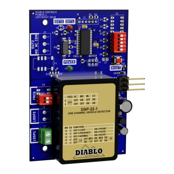
- Page 1 User Manual DSP-22-1 Low Power, Single Channel Vehicle Detector with Support for the Free-exit Probe Pros Who Know Trust Diablo DSP-22-1_MAN_D 11/23/2020 Page 1 of 22...
-
Page 2: Table Of Contents
Power LED Intermittently Comes On (Not Once Every 2 Seconds) ..............20 Detect LED Intermittently Comes On / Stays On Without a Vehicle Present ............20 Detect LED Will Not Come On With a Vehicle Present ..................21 DSP-22-1 User Manual Page 2 of 22 DSP-22-1_MAN_D... -
Page 3: Figures
Figure 4: Saw Cut for Home Run Exit and Chiseled Corner for Home Run Exit ............16 Figure 5 Typical Free-exit probe Installation ......................17 Figure 6 Side of Driving Surface Free-exit probe Installation .................. 18 DSP-22-1 User Manual Page 3 of 22 DSP-22-1_MAN_D... -
Page 4: Introduction
1. Introduction The DSP-22-1 detector is intended to be a single channel detector that can work with both inductive loops as well as the new Diablo Control Free-exit probe. The detector is powered by a high-performance 8-bit microcontroller that does not skimp on performance. The DSP-22-1 detector has a small footprint and was designed to directly plug into many DoorKing operators. -
Page 5: Functional Data
In Detect 26.43 milliamps typical @ 20VDC. Environmental Data Operating Temperature: -35°F to 165°F (-37°C to 74°C) Storage Temperature: -40°F to 176°F (-40°C to 80°C) Humidity: Up to 95% relative humidity non-condensing DSP-22-1 User Manual Page 5 of 22 DSP-22-1_MAN_D... -
Page 6: Mechanical Data
Mounting Position: Housing Material: Lexan Detector Size: 4.300 inches (High) x 2.950 inches (Wide) x .820 inches (Deep) 109.22 mm (High) x 74.93 mm (Wide) x 20.83 mm (Deep) Figure 2: Physical Dimensions DSP-22-1 User Manual Page 6 of 22 DSP-22-1_MAN_D... -
Page 7: Features And Functions
(DIP switch 1 OFF and DIP switch 2 OFF). Like most inductive loop vehicle detectors, the DSP-22-1 directly measures the change in frequency of the loop and from there, calculates the change in inductance when a vehicle interacts with it. The change in inductance is measured as %ΔL/L (reads as “percent delta L over L”). -
Page 8: Channel 1 - Frequency (S3 Dip Switches 1 And 2)
When the probe mode of operation is selected (DIP switch 5 ON), pulse on entry is the only detection mode of operation for Channel 1. If DIP switch 5 is OFF and DIP switch 4 is ON, Channel 1 is in the pulse mode. DSP-22-1 User Manual Page 8 of 22... -
Page 9: Channel 1 - Loop / Probe (Dip Switch 5)
Channel 1 – Loop / Probe (DIP Switch 5) The DSP-22-1 is capable of operating with either a standard inductive loop or the new free-exit probe (magnetometer). As usual, the inductive loop operates in both presence and pulse modes. However, the free- exit probe (magnetometer) can only operate in pulse mode and will automatically override any settings to the contrary. - Page 10 The detector is equipped with the ability to remember prior faults that have occurred since the last power interruption or reset (changing a DIP switch or the sensitivity). The detector will hold this status for one week DSP-22-1 User Manual Page 10 of 22 DSP-22-1_MAN_D...
- Page 11 When the detector is in the low power mode (Green LED flashes on once every 2 seconds), the channel Detect LED will flash on at the same time. DSP-22-1 User Manual Page 11 of 22 DSP-22-1_MAN_D...
-
Page 12: Installation
L = ( (6 + 14 + 6 + 14) / 4) x (2 + 2 L = (40 / 4) x (2 + 4) L = 10 x 6 Loop Inductance is approximately 60µH. DSP-22-1 User Manual Page 12 of 22 DSP-22-1_MAN_D... -
Page 13: Detector Installation
Location: The detector should be plugged in to the appropriate connector on the DoorKing operator. Mounting: The detector will function when mounted in any orientation. Using the two holes in the detector, secure the detector in place. DSP-22-1 User Manual Page 13 of 22 DSP-22-1_MAN_D... -
Page 14: Loop Installation
The number of turns to use in a loop is dependent on the size of the loop and length of the lead-in. Rather than dive into all of the calculations to arrive at a value, we will just give you a table of safe values based on the number DSP-22-1 User Manual Page 14 of 22... - Page 15 This will also help remove dust from the saw cutting operation from the sides of the saw slot. This will allow better adhesion of the loop sealant to the saw slot. DSP-22-1 User Manual Page 15 of 22...
-
Page 16: Figure 3: Loop Installation
BACKER ROD PIECE LOOP WIRE CUTS DETAIL B DETAIL A Figure 3: Loop Installation Figure 4: Saw Cut for Home Run Exit and Chiseled Corner for Home Run Exit DSP-22-1 User Manual Page 16 of 22 DSP-22-1_MAN_D... -
Page 17: Free-Exit Probe Installation
Once the loop wire leaves the saw slot it should be twisted at least three times per foot. More is better. The twists should be kept tight to be most effective in reducing the effects of electrical interference. Free-exit probe Installation Figure 5 Typical Free-exit probe Installation DSP-22-1 User Manual Page 17 of 22 DSP-22-1_MAN_D... -
Page 18: Figure 6 Side Of Driving Surface Free-Exit Probe Installation
NOTE: When the roadway is greater than 11 feet wide requiring a greater detection zone you have the option to add a second Free-exit probe to the opposing side of the roadway. The probes must be wired in series. Figure 6 Side of Driving Surface Free-exit probe Installation DSP-22-1 User Manual Page 18 of 22 DSP-22-1_MAN_D... -
Page 19: Troubleshooting
Disconnect the loop wires for the detector. The LED should begin flashing just once every two seconds. If it does not change its flash count, change the detector. DSP-22-1 User Manual Page 19 of 22... -
Page 20: Detect Led Flashes At The Same Time As The Power Led Every Two Seconds
Physical Issues with the Loop – There are many ways in which a loop installation can go bad. The insulation of the loop wire can fail. This can be due to the loop wire being exposed in the saw lot, damage to the wire insulation DSP-22-1 User Manual Page 20 of 22... -
Page 21: Detect Led Will Not Come On With A Vehicle Present
The first thing to do is verify that the LED in question is still working. This is accomplished by a quick lamp test. Reset the detector by pressing the RESET button. All three LEDs should turn off and turn on. If a Detect LED does not illuminate, replace the detector. DSP-22-1 User Manual Page 21 of 22 DSP-22-1_MAN_D... - Page 22 If the problem follows the loop the loop is the problem. If it stays in the same detector, replace the detector. DSP-22-1 User Manual Page 22 of 22...
Need help?
Do you have a question about the DSP-22-1 and is the answer not in the manual?
Questions and answers