
Related Manuals for Diablo DSP-10


Summary of Contents for Diablo DSP-10
- Page 1 User Manual DSP-10 Vehicle Detector Pros Who Know Trust Diablo Page 1 of 26 DSP10_MAN_C 07/27/18...
-
Page 2: Table Of Contents
Power LED Shows Two Quick Flashes Once Every Two Seconds................24 Detect LED Intermittently Comes On / Stays On Without a Vehicle Present ............25 Detect LED Will Not Come On With a Vehicle Present ..................26 DSP-10 User Manual Page 2 of 26 DSP10_MAN_C... -
Page 3: Figures
Figure 9: Loop Installation ............................20 Figure 10: Saw Cut for Home Run Exit and Chiseled Corner for Home Run Exit ............. 20 Figure 11: Fail-Safe and Fail-Secure Internal Jumpers .................... 22 DSP-10 User Manual Page 3 of 26 DSP10_MAN_C... -
Page 4: Introduction
2. Introduction The DSP-10 Detector is intended to be a top of the line single channel detector. Many features have been included which are normally found only on more expensive models. The small package is powered by a high- performance 16-bit microcontroller that does not skimp on performance. The DSP-10 Detector was designed to retrofit into existing locations that may require a detector upgrade. -
Page 5: Technical Data
10.5 volts to 30 volts AC or DC with over voltage protection 100 volts to 135 volts AC 200 volts to 270 volts AC Output Relay Rating: 3 amps @ 125 volts DSP-10 User Manual Page 5 of 26 DSP10_MAN_C... -
Page 6: Environmental Data
Mounting Position: Housing Material: Lexan Housing Size: 2.36 inches (High) x 1.75 inches (Wide) x 4.06 inches (Deep) 59.94 mm (High) x 44.45 mm (Wide) x 103.12 mm (Deep) Figure 2: Physical Dimensions DSP-10 User Manual Page 6 of 26 DSP10_MAN_C... -
Page 7: Features And Functions
The output will not pulse again until the loop has been reoccupied and any enabled delay has timed out. DSP-10 User Manual Page 7 of 26... -
Page 8: Fail-Safe Vs Fail-Secure
The B output is always fail-secure when not in the fail output mode. The DSP-10 is one of the few vehicle detectors that honors fail-safe and fail-secure even in the absence of power. Inside the unit, on the main PC board, are three jumpers that set the failure mode. When placed in the fail-safe position, the A output relay will be fail-safe in the absence of adequate voltage. -
Page 9: Fail Memory (Dip Switch 8)
For those instances where a longer period is desired, extended presence will hold that same vehicle for about 19 or 20 hours. This is quite a long time, but it isn’t infinite. The DSP-10 does not have infinite presence. -
Page 10: Figure 3: Outputs With No Delay Or Extension
Pulse on Exit: Every time the loop becomes vacant or a vehicle is tuned out, a single 250 milliseconds pulse will be output on the B output. Fail: If the DSP-10 recognizes some type of loop failure, a continuous output on the B output will be given. The B output will remain activated until the failure is corrected. -
Page 11: Sensitivity Boost (Dip Switch 4)
With this feature the detector may be able to detect the high-bed portion of the vehicle without having to be overly sensitive and susceptible to false detections. NOTE: If detection of high-bed tractor-trailers is required, correctly sized loops must be used. DSP-10 User Manual Page 11 of 26 DSP10_MAN_C... -
Page 12: Extension (Dip Switches 2 And 3)
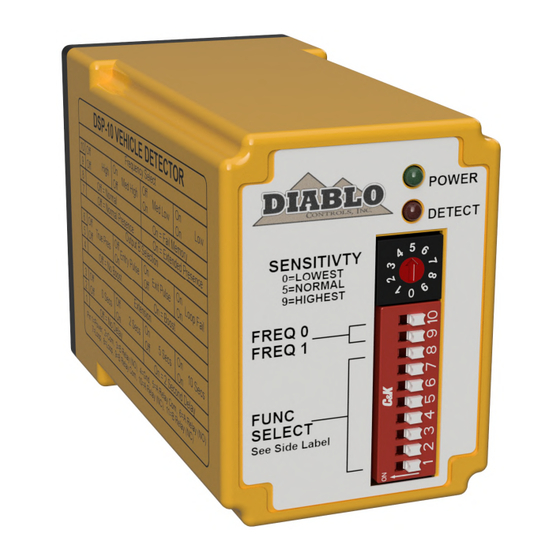
The delay interval is fixed at 2 seconds. Indicators The DSP-10 is equipped with two LED indicators: Power (Green) and Detect (Red). Power LED – The green power LED indicates these possible states: The voltage applied to the detector is less than the minimum display voltage of approximately 7.75 volts. - Page 13 50 milliseconds, on for 50 milliseconds, off for 50 milliseconds and then repeat the sequence until power is cycled or the detector reset. Normal The LED is always on when the detector is in its normal state of operation. DSP-10 User Manual Page 13 of 26 DSP10_MAN_C...
-
Page 14: Figure 7: Power Led States
LED will return to the off state. If the vehicle is still present after 2 seconds, the LED will become solid and the A output will be activated. DSP-10 User Manual Page 14 of 26 DSP10_MAN_C... -
Page 15: Figure 8: Detect Led States
Detect The LED will be on solid when a vehicle is being detected and the delay interval (if activated) has finished timing. Figure 8: Detect LED States DSP-10 User Manual Page 15 of 26 DSP10_MAN_C... -
Page 16: Installation
L = ( (6 + 14 + 6 + 14) / 4) x (2 + 2 L = (40 / 4) x (2 + 4) L = 10 x 6 Loop Inductance is approximately 60µH. DSP-10 User Manual Page 16 of 26 DSP10_MAN_C... -
Page 17: Detector Installation
Location: The detector should be plugged in to the appropriate connector on the DoorKing operator. Mounting: The detector will function when mounted in any orientation. Using the two holes in the detector, secure the detector in place. DSP-10 User Manual Page 17 of 26 DSP10_MAN_C... -
Page 18: Loop Installation
The number of turns to use in a loop is dependent on the size of the loop and length of the lead-in. Rather than dive into all of the calculations to arrive at a value, we will just give you a table of safe values based on the DSP-10 User Manual Page 18 of 26... - Page 19 This will also help remove dust from the saw cutting operation from the sides of the saw slot. This will allow better adhesion of the loop sealant to the saw slot. DSP-10 User Manual Page 19 of 26...
-
Page 20: Figure 9: Loop Installation
BACKER ROD LOOP WIRE DETAIL B DETAIL A Figure 9: Loop Installation Figure 10: Saw Cut for Home Run Exit and Chiseled Corner for Home Run Exit DSP-10 User Manual Page 20 of 26 DSP10_MAN_C... - Page 21 Once the loop wire leaves the saw slot it should be twisted at least three times per foot. More is better. The twists should be kept tight to be most effective in reducing the effects of electrical interference. DSP-10 User Manual Page 21 of 26...
-
Page 22: Configuration
10 to 30 volts, AC or DC (Low Voltage) 100 to 135 volts AC 200 to 270 volts AC There is only one wiring configuration (pin-out) offered. DSP-10-LV, DSP-10-117, and DSP-10-230: Wire Color Function Black DC + or AC Line hot... -
Page 23: Troubleshooting
Swap the loops between a working detector and a failing detector. If the problem follows the loop the loop is the problem. If it stays in the same detector, replace the detector. DSP-10 User Manual Page 23 of 26 DSP10_MAN_C... -
Page 24: Power Led Flashes Quickly (5 Hz)
Another is that the loop wire has been damaged where it enters or exits a conduit or junction box, or that a conduit that the loop wire is in has been damaged (crushed, kinked, bent, cut, etc.). DSP-10 User Manual Page 24 of 26 DSP10_MAN_C... -
Page 25: Detect Led Intermittently Comes On / Stays On Without A Vehicle Present
Another possibility is metal objects in close proximity to the loop. Utility manhole covers are objects that may move slightly when vehicle tires drive over them, especially if the vehicle turns while a tire in on the cover. Most DSP-10 User Manual Page 25 of 26... -
Page 26: Detect Led Will Not Come On With A Vehicle Present
If the problem follows the loop the loop is the problem. If it stays in the same detector, replace the detector. DSP-10 User Manual Page 26 of 26...
Need help?
Do you have a question about the DSP-10 and is the answer not in the manual?
Questions and answers