
Related Manuals for Daikin Super Unit SUT00S8007-30


Summary of Contents for Daikin Super Unit SUT00S8007-30
- Page 1 Super Unit SUT00S8007-30 SUT10S8007-30 SUT00D8021-30 SUT10D8021-30 SUT16D8021-30 Operation Manual DAIKIN INDUSTRIES, LTD. Oil Hydraulics Division PIM00424...
- Page 3 Introduction Thank you very much for selecting DAIKIN hydraulic unit "Super Unit". The hydraulic unit "Super Unit" drived by IPM motor provides overwhelmingly excellent energy conservation performance and advanced functions by using our unique hydraulic technology and energy saving IPM motor system.
-
Page 4: Table Of Contents
Safety Precautions ....................1-1 Chapter 1 Conventions of safety instructions in this manual ............1-1 Safety precautions........................1-1 1.2.1 Escape Clauses........................1-1 1.2.2 Limitations on Applications ....................1-1 1.2.3 General Precautions......................1-2 Precautions for Use ........................1-2 Using it safely ..........................1-3 1.4.1 Installation and wiring ......................1-3 1.4.2 Operation..........................1-4 1.4.3 Maintenance and inspection .................... 1-5 1.4.4 Disposal ............................ - Page 5 Chapter 9 Electric Wiring......................9-1 Wiring diagram ..........................9-2 Installation of breaker .........................9-2 Connecting the main power supply cable ................9-2 Connecting the I/O signal cable.....................9-3 9.4.1 Digital input ..........................9-4 9.4.2 Digital output..........................9-5 9.4.3 Contact output ........................9-6 Test Run......................10-1 Chapter 10 Panel Operation....................11-1 Chapter 11 11.1 Each part name of the operation panel ................11-1 11.2 Function of the operation panel ...................11-1 11.2.1 Functional overview......................11-1 11.2.2 Mode switching operation ....................11-2 11.3 Normal mode..........................11-2 11.4...
- Page 6 13.1.2 Alarm ............................13-1 13.1.3 Warning ...........................13-4 13.2 Periodic inspection ........................13-5 13.3 Cleaning and replacement.......................13-7 13.4 Oil cooler maintenance procedure (only for unit type SUT10, SUT16)....13-8 13.4.1 Removing the oil cooler ....................13-8 13.4.2 Disassembling the oil cooler ..................13-9 13.4.3 Clean the core........................13-9 13.4.4 Clean the AC fan........................13-9 13.4.5 Reassembling the oil cooler ...................13-9 13.5 Oil filling port (air breather) maintenance procedure (only for unit type SUT10, SUT16)................................ 13-10 13.5.1 Removing method ......................13-10 13.5.2 Cleaning method ......................13-10 13.5.3 Mounting direction ......................13-10 13.6 Suction strainer maintenance procedure (only for unit type SUT10, SUT16) 13-10 13.6.1 Removing method ......................
-
Page 7: Chapter 1 Safety Precautions
◆ DAIKIN shall not be responsible for any damage incidental to use of this product or impossibility to use this product (loss of business profit, discontinuation of business). -
Page 8: General Precautions
1.2.3 General Precautions DANGER Transportation, installation, piping, wiring, operations, maintenance and inspections must be conducted by qualified personnel. During the above work, wear protective gear required for safe work (work clothes, safety band, helmet, safety shoes, gloves and so on). ... -
Page 9: Using It Safely
If this unit is continuously used in the state that the safety valve is actuated, it may output an alarm due to a temperature rise and so on.In this case, re-adjust the high pressure safety valve pressure setting according to “13.8 High-pressure Safety Valve Adjustment Procedure”... -
Page 10: Operation
CAUTION ● Please make sure the installation environment meets the requirements. There is a risk of fire or accident. ● Please install in somewhere can withstand its weight. There is a risk of accident. ● Please do not apply static electricity to terminals. There is a risk of accident. ● ... -
Page 11: Maintenance And Inspection
1.4.3 Maintenance and inspection DANGER ● Only the qualified personnel can carry out the maintenance and inspection. There is a risk of electrical shock or injuries. ● Before operation please make sure the input power supply is OFF. There is a risk of electrical shock. ● ... -
Page 13: Chapter 2 Features And Structure
Features and Structure Energy-saving By using the highly efficient IPM motor driving system that DAIKIN originally developed, this hydraulic unit remarkably improved the energy efficiency of the motor. Two fixed displacement pumps (high-pressure small-capacity, low-pressure high-capacity) are adopted in this double-pump specification. -
Page 14: Multi-Stage Speed Control/Multi-Stage Pressure Control, And Shockless Control
Multi-stage speed control/Multi-stage pressure control, and shockless control functions ◆ The Super Unit enables multi-stage pressure control/flow rate control by selecting 16 patterns of P-Q characteristics that have been registered in the controller from the master machine. ◆ The Super Unit enables shockless control by setting/adjusting the rising/falling time at changes of the P-Q characteristics. ... - Page 15 Chapter 3 Specifications and Operating Conditions Model identification code 3.1.1 Format (g) (h) (j) (a) Series name ・SUT: SUT series (f) Design No. ・Advances according to model change (b) Tank capacity ・00: No tank (g) Selection of function * ・C: Communication function(RS232C)...
-
Page 16: Chapter 3 Specifications And Operating Conditions
3.1.2 Manufacturing Number ( i ) ( j ) ( k ) ( l ) ***** ( i ) Hardware revision history ( j ) Software revision history (*1) ( k ) Manufacture Date ( l ) Serial No. *1 ... -
Page 17: Common Specifications
3.2.2 Common Specifications Dedicated mineral hydraulic oil / Wear-resistant hydraulic oil (For recommended brands, refer to DAIKIN "Hydraulic Equipment General Catalog (HK196)".) (Note 1) Hydraulic oil ・ Viscosity grade: ISO VG 32 to 68 ・ Viscosity range: 15 to 400 mm2/s ・... -
Page 18: Typical P-Q Characteristic Diagram
responding the regenerative overload alarm raises and the unit stops depending on the main machine’s operating conditions and the load conditions. If the change is – side, the output characteristics may become low. (Note 3) If its operating temperature beyond the recommended temperature range, the pressure pulsation may increase, the discharge flow rate may reduce, but it is not a malfunction. -
Page 19: Dimensions
Dimensions ■Motor Pump Type (SUT00) SUT00S8007-30 PIM00424... - Page 20 SUT00D8021-30 PIM00424...
- Page 21 ■Unit Type (SUT10, SUT16) SUT10S8007-30 PIM00424...
- Page 22 SUT10D8021-30 PIM00424...
- Page 23 SUT16D8021-30 PIM00424...
-
Page 24: Hydraulic Circuit
Hydraulic circuit ■Motor Pump Type (SUT00) ● SUT00S8007-30 Drain port Anlord port (High pressure) (Low pressure) Suction port Part number Name Inverter-driven motor pump Controller AC fan Base Check valve 3-10 PIM00424... - Page 25 ● SUT00D8021-30 Drain port Anlord port (High pressure) (Low pressure) Suction port Part number Name Inverter-driven motor pump Controller AC fan Base Check valve 3-11 PIM00424...
- Page 26 ■Unit Type (SUT10, SUT16) ● SUT10S8007-30 Option port Above the oil surface Hose (Low pressure) (High pressure) Hose Hose Hose Part number Name Tank Suction strainer Stop valve Oil level gauge Oil port and air breather Inverter-driven motor pump Controller Oil cooler AC fan Return filter Check valve...
- Page 27 ● SUT10D8021-30, SUT16D8021-30 Option port Above the oil surface Hose (Low pressure) (High pressure) Hose Hose Hose Part number Name Tank Suction strainer Stop valve Oil level gauge Oil port and air breather Inverter-driven motor pump Controller Oil cooler AC fan Return filter Check valve 3-13 PIM00424...
-
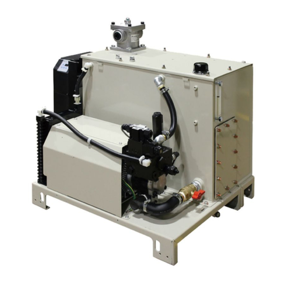
Page 29: Chapter 4 Names Of Unit Components
Chapter 4 Names of Unit Components ■Motor Pump Type (SUT00) Display the current pressure check valbe and operation panel Solenoid valve※ Controller Valve block AC fan Inverter driving pump ※Solenoid valve is not 《Unit front view》 attached to SUT00S8007-30 PIM00424... - Page 30 ■Unit Type (SUT10, SUT16) Return filter Tank Oil filling port (Air breather) Stop valve Controller Check valve 《Unit top view》 Display the current pressure Oil level and operation gauge panel Solenoid valve※ Valve block Inverter driving pomp Oil cooler ※Solenoid valve is not attached to SUT10S8007-30 《Unit front view》 PIM00424...
-
Page 31: Chapter 5 Start-Up Procedure
Chapter 5 Start-up Procedure Start-up Procedure are as follows. 1. Check ・・・・・・・・・・・・・・・・・・・・・・・・・・・・・Refer to “Chapter 6 Confirmation of the Arrival Product” 2. Transportation and installation ・・・・・・・・・・Refer to “Chapter 7 Transportation and Installation” 3. Piping ・・・・・・・・・・・・・・・・・・・・・・・・・・・・・Refer to “Chapter 8 Piping” ... -
Page 33: Chapter 6 Confirmation Of The Arrival Product
Chapter 6 Confirmation of the Arrival Product Package Contents CAUTION ● Please check the top and bottom of the product and unpack. There is a risk of fall. Opening the package, and confirm whether the followings are damaged. ・One hydraulic unit ・One simplified operation manual Form confirmation... -
Page 35: Chapter 7 Transportation And Installation
Chapter 7 Transportation and Installation Transportation 7.1.1 Transportation under packing condition Please use lift to haul this unit when it is under packing condition. Please refer to the illustration below for the point where you lift. The weight of the package can be found on a label affixed to the side. The weight label ... -
Page 36: Installation
■Products Weight ● Motor Pump Type (SUT00) ● Unit Type (SUT10, SUT16) Product Type Weight [kg] Product Type Weight [kg] SUT00S8007-30 SUT10S8007-30 SUT00D8021-30 SUT10D8021-30 SUT16D8021-30 * The weight does not include the hydraulic oil. DANGER If other parts (such as pump pipe) besides the long hooking hole are used to hook, there is a risk of falling or collapse. -
Page 37: Fixation Of The Unit
WARNING If the intake / exhaust space above can not be ensured, the heat exchange efficience of the oil cooler / AC fan will be reduced. There is a risk of burns because the hydraulic oil and equipment will become extremely hot. So, please keep the intake / exhaust space as shown in the figure above. -
Page 39: Chapter 8 Piping
Chapter 8 Piping Piping ■Motor pump type (SUT00) There are different port types below for motor pump types. Please pipe all ports. The details of the pipe position is separately described in the model drawing. Please use hose and sealing tape to pipe. ... - Page 40 DANGER ● During piping, please make sure the bending radius of the hydraulic hose satisfy the manufacturer recommended value. As for the hose fixing method, please follow the hose manufacturer recommended method. CAUTION ● Please make sure the suction pressure is under -0.02MPa. If it becomes more than -0.02MPa, the flow rate may reduce and the noise may become large.
-
Page 41: Filling Hydraulic Oil (Only Sut10, Sut16)
Filling hydraulic oil (Only SUT10, SUT16) ● Remove the cap of the oil filling port (air breather) by turning it counterclockwise, and fill clean hydraulic oil (pollution degree: NAS Class 9 or lower level) into the tank. Set the oil level so that the float of the level gauge is between the red and yellow lines. -
Page 43: Chapter 9 Electric Wiring
Chapter 9 Electric Wiring ・ This hydraulic unit needs connections of main power cables and I/O signal cables as required. ・ Please remove the controller cover by loosening and removing the Cross head screws M4×4, then connect the main power cables and I/O signal cables. After completing the wiring, please replace the controller cover. The recommended tightening torque is 1.0 N・m. -
Page 44: Wiring Diagram
Wiring diagram 3φ AC200〜220V 50/60Hz L1 Main circuit L2 power supply Digital output DO1 L3 Negative Positive Digital input DI1 common common DO2 DI2 or DI3 OCOM ・ ・ ・ ・ External power ... -
Page 45: Connecting The I/O Signal Cable
Power supply terminal block (Screw color:silver) Connect a ground cable to the specified position Main power supply connection port φ28 Ground terminal DANGER ● Please use the AC power supply which is suitable for the power specifications of this product. ● Please use cables which is suitable for the power supply capacity. ● ... -
Page 46: Digital Input
AGND AGND AL̲B DIN6 DIN2 AGND AGND OCOM DIN8 DIN4 ICOM AIN2 AL̲C DIN7 DIN3 AIN1 AL̲A DIN5 DIN1 I/O signal terminal block signal line connection port φ21 Terminal Function of Terminal Function of Signal name Signal name name terminal name terminal Alarm output AL_C DIN5... -
Page 47: Digital Output
DIN2 Digital input 2 DIN3 Digital input 3 P-Q selection No. 0 to 15 can be selected depending on the combination of digital input status. Shown in the following table. DIN4 Digital input 4 DIN5 Digital input 5 Note) While the unit is stopped by digital input 1, the panel shows “STP”. Note) Set the time between unit stop and unit start at 0.5 seconds or more. -
Page 48: Contact Output
Load External power supply(DC24V) MAX 50mA Load OCOM CAUTION ● As the external power supply, prepare a 24 VDC ±1 V, 0.5 A power supply. Power cannot be supplied from this controller to external equipment. -
Page 49: Chapter 10 Test Run
Chapter 10 Test Run CAUTION ● Make sure the power is able to be quickly shut off. ● If unexpected action occurs, please make sure that it is safe, then operate it. Refer to "Chapter5 Start-up Procedure", and make sure that all preparation has been completed. ①Start check Turn ON the switch on the machine control panel、supply the power to the unit. -
Page 51: Chapter 11 Panel Operation
Chapter 11 Panel Operation 11.1 Each part name of the operation panel Data displey The operation panel is comprised of the 3- (3 digits) digit LED as shown in the left figure. There are four switch keys. MODE key ENT key Normally, the panel shows an actual pressure ... -
Page 52: Mode Switching Operation
11.2.2 Mode switching operation Switching among these modes as shown in figure below. Please refer to the description of each mode for details of operation. Power ON Normal mode Press the Press the key at the same time key at the same time for 2 seconds. ... -
Page 53: Monitor Mode
11.4 Monitor mode 11.4.1 Monitor mode display item list In monitor mode, you can monitor the items in the table below by panel operation. Monitor Name Unit Remarks number Pressure switch setting Displays the pressure switch setting. ×10PSI Displays the pressure settings of the current P-Q selection Pressure setting number. -
Page 54: Operation Of The Monitor Mode
Monitor Name Unit Remarks number ― (Reserved for system) Reserved for system Note1) You can check the power-ON count by pressing the key when an alarm code is displayed. Note If the power-ON times shown in “n04: Latest alarm code” exceeds 999 times, it will be cleared to 0. 11.4.2 Operation of the monitor mode Monitor ode ... -
Page 55: Setting Mode
Setting mode 11.5 Please refer to "Chapter 12 Parameter" for setting mode parameters. 11.5.1 Operation of the setting mode Normal mode ① Press the key at the same time for 2 seconds Setting mode Data number selection Display the value Edit the value ② ③ ④ or ・・・・ ⑤ Determine The next number after the maximum number returms to n00 ... - Page 56 ■PQ selection parameter Nomal mode ① key at the same time for 2 second Press the Setting mode ⑦Date selection and value display/edit ② Date number selection ③ Pressure of the high pressure side ※1 ④ edit the value ⑤ or after 2 second after 2 second after 2 second ⑥ Flow rate of the high pressure side ※1 ⑧ or after 2 second ・・・・ after 2 second after 2 second Pressure of the low pressure side or after 2 second after 2 second after 2 second PQ selection parameters are P13〜P28. Flow rate of the low pressure side or ...
- Page 57 ⑤ Press the key to change the setting value. After changing the setting value, data symbol appears about two seconds later. ⑥ Press to determine the data number. The next data number will be displayed. ⑦ Repeat ④, ⑤, ⑥...
-
Page 58: Alarm Mode
11.6 Alarm mode In alarm mode, you can see up to 10 alarm histories that have occurred in the past. Please refer to "13.1.2 alarm" for the alarm code. 11.6.1 Operation of the alarm mode Nomal mode Press the key at the same time for 2 seconds ... - Page 59 ④ Press any key among to go back to the alarm history number. No. Panel display Representation Unit Remarks Alarm Content Alarm Content The number of Power on times when an alarm Power on times times occurs Rotational speed 10min Motor speed at the time of alarm PQ number and pump state at the time of alarm...
-
Page 61: Chapter 12 Parameter Adjustment
Chapter 12 Parameter Adjustment 12.1 Parameter List The default value of the parameter P13 ~ 28 is different, depending on the unit type. Please refer to Page 12-6 “Table 1: Different default parameter values for different products” for the default value of the parameter P13 ~ 28. - Page 62 Default Item Sign Name Operating range Description Reference setting Set the output signal at the time of warning occurrence. Warning output P07 WN_M 0〜2 12-11 Please refer to " P08: Alarm output mix " level setting for more information. Select the output method and output terminal of the alarm signal, pressure switch signal and warning signal,...
- Page 63 Default Item Sign Name Operating range Description Reference setting surge pressure is more likely to occur. In addition, if set to 0, the acceleration response gain will become the maximum that is defined by the controller. And the acceleration time will become the minimum.
- Page 64 Default Item Sign Name Operating range Description Reference setting parameter to avoid the unstable state. Set the conditions of the motor speed when switching to single mode from confluence. When the confluence flow rate drops from the parameter ”high-pressure side Single switching −...
- Page 65 Default Item Sign Name Operating range Description Reference setting Setting the function of the signal to be output from the digital output DO1. 0: PQ number switching completion output 1: Motor running output Digital output 2: High-pressure side operation output DO_S 12-11 0〜7...
- Page 66 ■■■■■ ●●■■■■■ Please confirm the corresponding column in the " " in SUT -30 for the mode code of your product. ■ Table 1: PQ setting list Product Type (SUT●●■■■■■-30) Name S8007 D8021 The default value [MPa] Range 1.5〜20.6 High-pressure side pressure setting...
-
Page 67: P00: Di_A] Valid Logic Switch Of The Start-Stop Signal
12.2 [P00: DI_A] Valid logic switch of the start-stop signal You can make the motor start / stop by the input signal of the digital input terminal DIN1. This parameter allows you to switch the effective logic of the digital input terminal DIN1. Factory Sign Name... -
Page 68: Pressure / Flow Rate Property And Pq Selection
12.3 Pressure / flow rate property and PQ selection 12.3.1 PQ selection parameter You can set several parameters in every PQ selection number, such as, maximum pressure, maximum flow rate, acceleration and deceleration time of pressure / flow rate at the time of switching PQ number. Display Sign * Parameter Name... -
Page 69: Pq Selection
◆High-pressure and low-capacity operation Flow rate 「QH*:High-pressure side flow rate setting」 Pressure 0 「PH*:High-pressure side pressure setting」 * Please refer to "12.3.3 [P40: PL_D] Settings when operating only at high pressure side (single) " for more information about how to set the high-pressure and low-capacity operation. ... -
Page 70: P40: Pl_D] Settings When Operating Only At High Pressure Side (Single)
◆Example of the PQ selection switching (Three-stage pressure) PQ14: Pressure Setting Value PQ5: Pressure Pressure Setting Value PQ2: Pressure Setting Value 0 Time Digital Input 2 ON OFF OFF (PQ Selection 1) Digital Input 3 ON OFF ON (PQ Selection 2) Digital Input 4 OFF ON (PQ Selection 3) Digital Input 5 ON OFF (PQ Selection 4) ◆Pressure and flow rate change time when the PQ selection switches PQ1:Pressure in PQ0:Deceleration time high pressure side PQ1:Acceleration time 1MPa Pressure Change Time ... -
Page 71: Output Signal Setting
12.4 Output signal Setting The digital output, and the signal type can be selected by parameters, as shown in the table below. 12.4.1 Parameter ■Parameters for output signal Factory Default Display Sign Parameter Name Range Unit Setting WN_M Warning output level 0〜2 AMIX Alarm output mix... - Page 72 Pressure [MPa] 「P26:The minimum value of pressure coincidence Pressure command×「P25:Pressure detection」 coincidence detection range」/100 Pressure Command Pressure command×「P25:Pressure 「P26:The minimum value of coincidence detection range」/100 pressure coincidence detection」 Flow rate [L/min] 「P26:The minimum value of flow rate coincidence Flow rate command×「P27:Flow rate detection」 coincidence detection range」/100 Flow rate command Flow rate command×「P27:Flow rate 「P26:The minimum value of coincidence detection range」/100 flow rate coincidence detection」 The timing diagram of the coincidence signal output is shown in the following figure. Pressure coincidence detection range ...
-
Page 73: P08: Amix] Alarm Mix Output, [P07: Wn_M] Warning Output Level
12.4.3 [P08: AMIX] Alarm mix output, [P07: WN_M] Warning output level By changing the parameter `P08: Alarm mix output’ ‘P07: Warning output level’, the digital output DO2 and contact output function can be selected. ◆ Digital output DO2 and contact output Parameter Output signal Digital output DO2... -
Page 74: Parameter Description
12.5.2 Parameter description 12.5.2 Parameter Settings Function Name When the warning “L63: Pressure switch operation” occurs, you can keep the "L63" displaying on the operation panel. And, you can register the “L63: Pressure switch operation” in the alarm history. L63 display Register in the Value... - Page 75 ■Changing the pressure switch unit by ” P08 Alarm output mix” ◆Pressure Unit:the setting value of “P08:Alarm output mix” is “0” or “1” The pressure setting value o f each PQ selection The setting value of prssure switch [MPa] Time ◆Pressure Unit:the setting value of “P08:Alarm output mix” is “2” The pressure setting value o f each PQ selection The setting value of pressure switch[%] ⇒The ratio parameter 時間 Time “Pressure setting value”[%] ■Pressure switch working example Pressure 「P01:Pressure switch operating level」 ...
-
Page 76: Other Functions
12.6 Other functions 12.6.1 [P12: W_TM] Solenoid valve response delay time at the time of switching PQ selection After switching the PQ pattern, it will change the pressure command or the flow rate command after a delay determined by this parameter. -
Page 77: P45: Ac_F] Ac Fan Start-Stop Signal Synchronization Settings
■Co mmand at unit start, and change of motor output Pressure command P32: Surge less start-up time – 100[ms] Pressure setting in high pressure side Time 0 Flow rate command P32: Surge less start-up time – 100[ms] Flow rate setting in high pressure side Time ... - Page 78 Motor temperture 80℃ Dead zone ※ 75℃ 0 Time AC fan Digital input 1 Start Stop Start (Start-Stop signal) 12-18 PIM00424...
-
Page 79: Chapter 13 Troubleshooting
Chapter 13 Troubleshooting 13.1 Protection function 13.1.1 Output signal of the protection function The table below is output signal of the protection function, depending on the setting of parameter "P08: Alarm output mix". ○: Circuit is conducting ×: Circuit is not conducting Alarm output mix P08: 0: Individual output... - Page 80 Alarm Name Reason Countermeasure Code ・ Replace the motor pump Failure of the encoder ・ Replace the controller Failure of the controller ・ Replace the motor pump Overspeed Failure of the encoder Motor rotation speed exceeded ・ Replace the controller Failure of the controller 120% of the maximum rotational speed...
- Page 81 Alarm Name Reason Countermeasure Code ・ Replace the controller Magnetic pole detection error Abnormality of the output device Magnetic pole detection is not completed within the specified time ・ Replace the encoder harness Encoder disconnection Disconnection or connection failure of the encoder harness Encoder cable break ・...
-
Page 82: Warning
Alarm Name Reason Countermeasure Code The heat dissipation fin ・ Replace the controller Failure of the controller thermistor is short-circuited or disconnected ・ Replace the fuse for cooling fan Fin temperature abnormal The cooling fan for controller is rise stopped ・... -
Page 83: Periodic Inspection
Warning Name Reason Countermeasures Code ・ Replace or clean the radiator Radiator is clogged the specified value 83℃ for 10 seconds or more ・ Check the leakage amount in Rotation speed of the motor is rising the main unit side circuit ・... - Page 84 ● Please note that the foreign matters may enter your eyes at the time of air blow. ● Please note that the oil will flow out from the pipe during decomposition. And please make sure that there is no residual pressure in the pipe. ● ...
-
Page 85: Cleaning And Replacement
13.3 Cleaning and replacement Item Inspection Time Inspection Method ● Oil tank Once / year Replace hydraulic oil periodically. ・Oil replacement If the oil is used without replacement for a long period, it has bad influences on operation and service life of the hydraulic unit. ●... -
Page 86: Oil Cooler Maintenance Procedure (Only For Unit Type Sut10, Sut16)
13.4 Oil cooler maintenance procedure (only for unit type SUT10, SUT16) WARNING Please stop operation and turn off the main power before maintenance. Please wear gloves and protective glasses. i ) Please pay attention to the fin portion of the core because it is sharp. ii ) Please note that the foreign matters may enter your eyes at the time of air blow. -
Page 87: Disassembling The Oil Cooler
13.4.2 Disassembling the oil cooler ① Remove the cross recessed hexagon head bolts (M5×L12: 2pieces), and separate the shroud from the core. ② Remove the cross recessed head machine screws (M4×L70: 2 pieces), and separate the AC fan and finger guard from the shroud. -
Page 88: Oil Filling Port (Air Breather) Maintenance Procedure (Only For Unit Type Sut10, Sut16)
13.5 Oil filling port (air breather) maintenance procedure (only for unit type SUT10, SUT16) 13.5.1 Removing method The cap can be easily removed by turning it counterclockwise by hand. ◎Cap 13.5.2 Cleaning method Blow air onto the filter to blow off dust accumulated on/adhering to the filter. Remove dust from inside of the strainer cylinder. -
Page 89: Replacement Of The Return Filter Element (Only For Unit Type Sut10, Sut16)13-11
13.7 Replacement of the return filter element (only for unit type SUT10, SUT16) When the detector indicates that the filter is clogged (the indicator ring is Green raised to hide the green part of the indication column completely), replace Red indication part the filter element according to the procedure below. -
Page 90: High-Pressure Safety Valve Adjustment Procedure
13.8 High-pressure Safety Valve Adjustment Procedure In the following three conditions, please re-adjust the setting of the high-pressure safety valve, by referring to “High-pressure Safety Valve Adjustment Procedure” described below. 1. Even if the hydraulic unit is used with the maximum pressure setting, the safety valve will not be activated under normal pressure control (except for the transient period when the circuit is blocked due to stop of the master machine hydraulic actuator). - Page 91 圧力調整ネジ長さ(目安) Pressure adjusting screw length (Standard) Pressure adjusting screw length 21.0 19.5 18.0 16.5 15.0 13.5 12.0 10.5 Lock nut 《Saftey valve detail drawing》 13.5 14.0 14.5 15.0 15.5 16.0 16.5 圧力調整ネジ長さ(mm) Pressure adjusting screw length (mm) 13-13 PIM00424...
-
Page 93: Chapter 14 Output Signal Timing Chart
Chapter 14 Output Signal Timing Chart About the start-stop signal (digital input 0), the setting value of [P11: start-stop signal switching] is "1" (default). If the setting value of [P11: start-stop signal switching] is changed to "0", the ON and OFF of the start-stop signal (digital input 0) will be inverted. -
Page 94: Timing Chart Of Pq Selection Switch
14.1.3 Timing chart of PQ selection switch Power (200V) DIN1 (Start-Stop Signal) Digital DIN2 Input (Digital input 2) DIN3 (Digital input 3) DIN4 (Digital input 4) DIN5 (Digital input 5) PQ number switch completion output DOUT0 Motor running output Output Selectio... -
Page 95: Chapter 15 Hybrid-Win (Maintenance And Management Function)
Chapter 15 Hybrid-Win (Maintenance and Management Function) Hybrid-Win is a tool that can manage and read the information in Daikin hybrid system (such as, Super Unit, EcoRich, Oil Cooler) by a computer. You can monitor or set parameters efficiently, by Windows in the computer.
Need help?
Do you have a question about the Super Unit SUT00S8007-30 and is the answer not in the manual?
Questions and answers