
Subscribe to Our Youtube Channel
Related Manuals for Daikin EcoRich R EHU15R-M0701-30


Summary of Contents for Daikin EcoRich R EHU15R-M0701-30
- Page 1 Hybrid Hydraulic System EcoRich R EHU15R-M0701-30 EHU15R-M0702-30 EHU30R-M0701-30 EHU30R-M0702-30 Operation Manual DAIKIN INDUSTRIES, LTD. Oil Hydraulics Division PIM00411...
- Page 2 Introduction Thank you very much for selecting DAIKIN hydraulic unit "EcoRich R". The hydraulic unit "EcoRich R" drived by IPM motor provides overwhelmingly excellent energy conservation performance and advanced functions by using our unique hydraulic technology and energy saving IPM motor system.
-
Page 3: Table Of Contents
Chapter 1 Safety Precautions ....................1-1 Conventions of safety instructions in this manual ............1-1 Safety precautions........................1-1 1.2.1 Escape Clauses........................1-1 1.2.2 Limitations on Applications ....................1-1 1.2.3 General Precautions......................1-2 Precautions for Use ........................1-2 Using it safely ..........................1-3 1.4.1 Installation and wiring ...................... - Page 4 Wiring diagram ..........................9-2 Installation of breaker .........................9-2 Connecting the main power supply cable ................9-2 Connecting the I/O signal cable.....................9-3 9.4.1 Digital input ..........................9-5 9.4.2 Digital output..........................9-6 9.4.3 Contact output ........................9-6 Chapter 10 Test Run......................10-1 Chapter 11 Panel Operation....................11-1 11.1 Each part name of the operation panel ................11-1 11.2...
- Page 5 13.2 Periodic inspection ........................13-5 13.3 Cleaning and replacement.......................13-7 13.4 Oil cooler maintenance procedure ..................13-8 13.4.1 Removing the oil cooler ....................13-8 13.4.2 Disassembling the oil cooler ..................13-9 13.4.3 Clean the core........................13-9 13.4.4 Clean the AC fan........................13-9 13.4.5 Reassembling the oil cooler ...................13-9 13.5 Oil filling port (air breather) maintenance procedure..........
-
Page 6: Chapter 1 Safety Precautions
◆ DAIKIN shall not be responsible for any damage incidental to use of this product or impossibility to use this product (loss of business profit, discontinuation of business). -
Page 7: General Precautions
1.2.3 General Precautions DANGER Transportation, installation, piping, wiring, operations, maintenance and inspections must be conducted by qualified personnel. During the above work, wear protective gear required for safe work (work clothes, safety band, helmet, safety shoes, gloves and so on). Do not use this unit under conditions other than those specified in the catalog or delivery specifications. -
Page 8: Using It Safely
Using it safely This manual and other annexes should be read before installation, operation and maintenance. After being familiar with all of the precautions and safety information of this equipment, please correctly use it. 1.4.1 Installation and wiring DANGER ● Only the qualified personnel can do the wiring work. There is a risk of electrical shock or fire. ●... -
Page 9: Maintenance And Inspection
CAUTION ● Please set the pressure and flow rate in the permissible range of the machine. There is a risk of accident ● Before operation, please set the parameters according to the machine. There is a risk of damage or mechanical failure. -
Page 10: Chapter 2 Features And Structure
Chapter 2 Features and Structure Energy-saving By using the highly efficient IPM motor driving system that DAIKIN originally developed, this hydraulic unit remarkably improved the energy efficiency of the motor. Multi-stage speed control/Multi-stage pressure control, and shockless control functions ◆ The Super Unit enables multi-stage pressure control/flow rate control by selecting 16 patterns of P-Q characteristics that have been registered in the controller from the master machine. -
Page 11: Chapter 3 Specifications And Operating Conditions
Chapter 3 Specifications and Operating Conditions Model identification code 3.1.1 Format (a) Series name (e) Design No. ・EHU**R: EcoRich R series ・Advances according to model change (b) Maximum pump discharge rate (f) Selection of function ・15: 15.2 L/min ・C: Communication function(RS232C) ・30: 28.5 L/min ・P: Analog input command function ・No symbol: Standard product... -
Page 12: Product Specification
Specifications and operating conditions 3.2.1 Product specification EHU15R-M0701-30 EHU30R-M0701-30 Product type EHU15R-M0702-30 EHU30R-M0702-30 Maximum operating (MPa) pressure Maximum flow rate (L/min) 15.2 28.5 (*1) Operating pressure (MPa) 0.5~7.0 adjusting range Operating discharge rate adjusting range (L/min) 2.5 ~ 15.2 3.5 ~ 28.5 (*1)... -
Page 13: Common Specifications
3.2.2 Common Specifications Dedicated mineral hydraulic oil / Wear-resistant hydraulic oil (For recommended brands, refer to DAIKIN "Hydraulic Equipment General Catalog (HK196)".) (Note 1) Hydraulic oil ・ Viscosity grade: ISO VG 32 to 68 ・ Viscosity range: 15 to 400 mm2/s ・... - Page 14 (*1,2) Typical P-Q characteristic diagram EHU15R-M0701-30 EHU15R-M0701-30 EHU30R-M0701-30 EHU30R-M0701-30 EHU15R-M0702-30 EHU15R-M0702-30 EHU30R-M0702-30 EHU30R-M0702-30 27.9 27.9 14.6 14.6 (21.9) (21.9) (4.9) (4.9) 圧力[MPa] 圧力[MPa] 圧力[MPa] 圧力[MPa] Pressure (MPa) Pressure (MPa) *1 The above charts show the typical characteristics when the oil temperature is 40 ° C. *2 The above PQ characteristics show the usable range by actual flow rate.
-
Page 15: Dimensions
Dimensions 3- 5 PIM00411... -
Page 16: Hydraulic Circuit
Hydraulic circuit Above the oil surface Hose Hose Part number Name Tank Suction strainer Oil level gauge Inverter-driven motor pump Controller Oil port and air breather Oil cooler AC fan PIM00411... -
Page 17: Chapter 4 Names Of Unit Components
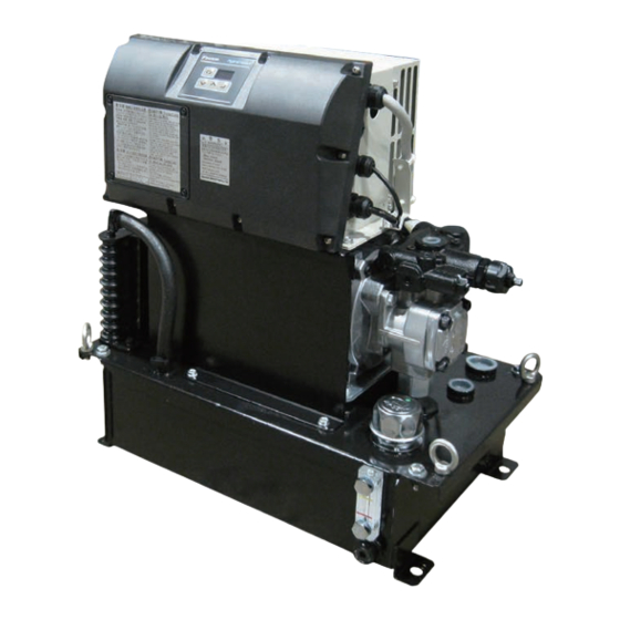
Chapter 4 Names of Unit Components Display the current pressure Controller and operation panel Motor AC fan Safety valve Oil cooler Hydraulic pump Oil filling port (Air breather) tank Oil level gauge Oil filling/drain port(Rc 3/8) 《Unit font view》 4- 1 PIM00411... -
Page 18: Chapter 5 Start-Up Procedure
Chapter 5 Start-up Procedure Start-up Procedure are as follows. ・・・・・・・・・・・・・・・・・・・・・・・・・・・・・ Refer to “Chapter 6 Confirmation of the Arrival Product” 1. Check ・・・・・・・・・・ Refer to “Chapter 7 Transportation and Installation” 2. Transportation and installation ・・・・・・・・・・・・・・・・・・・・・・・・・・・・・ Refer to “Chapter 8 Piping” 3. Piping ・・・・・・・・・・・・・・・・・・・・・・・... -
Page 19: Chapter 6 Confirmation Of The Arrival Product
Chapter 6 Confirmation of the Arrival Product Package Contents CAUTION ● Please check the top and bottom of the product and unpack. There is a risk of fall. Opening the package, and confirm whether the followings are damaged. ・ One hydraulic unit ・... -
Page 20: Chapter 7 Transportation And Installation
Chapter 7 Transportation and Installation Transportation 7.1.1 Transportation under packing condition Please use lift to haul this unit when it is under packing condition. Please refer to the illustration below for the point where you lift. The weight of the package can be found on a label affixed to the side. The weight label WARNING ●... -
Page 21: Installation
DANGER If other parts (such as pump pipe) besides the long hooking hole are used to hook, there is a risk of falling or collapse. Check the weight of the hydraulic unit in the above table, please make sure it is under the lift rated load. WARNING During the transportation, must equally hook at four points of the long hooking hole. -
Page 22: Fixation Of The Unit
CAUTION If the intake / exhaust space above can not be ensured, the motor or controller will become hot, and the life of the equipment will be reduced significantly. Please keep the intake / exhaust space as shown in the figure above. -
Page 23: Chapter 8 Piping
Chapter 8 Piping Piping Please be sure to pipe the following ports.The details of the pipe position is separately described in the model drawing. Please use hose and sealing tape to pipe. Pipe port Pipe size Recommended hose pressure Default Dischage port Rc 3/8 10.5MPa... -
Page 24: Filling Hydraulic Oil
Filling hydraulic oil ・ Remove the cap of the oil filling port (air breather) by turning it counterclockwise, and fill clean hydraulic oil (pollution degree: NAS Class 9 or lower level) into the tank. Set the oil level so that the float of the level gauge is between the red and yellow lines. -
Page 25: Chapter 9 Electric Wiring
Chapter 9 Electric Wiring ・ This hydraulic unit needs connections of main power cables and I/O signal cables as required. ・ Please remove the controller cover by loosening and removing the Cross head screws M4×4, then connect the main power cables and I/O signal cables. After completing the wiring, please replace the controller cover. The recommended tightening torque is 1.0 N ・... -
Page 26: Wiring Diagram
Wiring diagram 3φ AC200~220V 50/60Hz Main circuit power supply Digital output Negative Digital input Positive common common OCOM External power External power supply(DC+24V) supply(DC+24V) AL_C ICOM AL_B AL_A Negative Positive common common :It is located in the "main power supply terminal" of the controller. Please be sure to wire :It is located in the "signal line terminal"... -
Page 27: Connecting The I/O Signal Cable
3 ) Please connect the power line to the terminal base. Because the ground connection bis is different from the power supply line’s connection terminal, please not be confused. The recommended tightening torque is 2.4 N ・ m. For terminal fixing (screw color: black) ※... -
Page 28: 9.4.1 Digital Input
AGND AGND Shield AGND ground AIN2 AGND terminal AIN1 AL_C AL_B AL_A OCOM DIN8 DIN7 Signal line DIN6 DIN5 Connection DIN4 DIN3 port φ21 DIN2 DIN1 ICOM Terminal Function of Terminal Function of Signal name Signal name name terminal name terminal Alarm output AL_C... - Page 29 9.4.1 Digital input These terminals are used for sequence input signals that control the unit operations from external equipment. Connect these terminals as required, with reference to the table below. Terminal Signal name Remarks name ICOM Digital input COM Both positive and negative signals are acceptable. Used for start/stop control.
- Page 30 9.4.2 Digital output The alarm output single of this unit is a digital signal. Connect these terminals as required, with reference to the table below. Terminal : Signal name Output content factory setting name When switching the PQ number, it becomes ON if the pressure Digital output 1 command, flow rate command has reached the goal Digital output 2...
-
Page 31: Chapter 10 Test Run
Chapter 10 Test Run CAUTION ● Make sure the power is able to be quickly shut off. ● If unexpected action occurs, please make sure that it is safe, then operate it. Refer to "Chapter5 Start-up Procedure", and make sure that all preparation has been completed. ①Start check Turn ON the switch on the machine control panel、supply the power to the unit. -
Page 32: Chapter 11 Panel Operation
Chapter 11 Panel Operation 11.1 Each part name of the operation panel Data displey The operation panel is comprised of the 3- (3 digits) digit LED as shown in the left figure. There are four switch keys. MODE key ENT key Normally, the panel shows an actual pressure value UP key... -
Page 33: Mode Switching Operation
11.2.2 Mode switching operation Switching among these modes as shown in figure below. Please refer to the description of each mode for details of operation. Power ON Normal mode Press the Press the key at the same time key at the same time for 2 seconds. -
Page 34: Monitor Mode
11.4 Monitor mode 11.4.1 Monitor mode display item list In monitor mode, you can monitor the items in the table below by panel operation. Monitor Name Unit Remarks number Pressure switch setting Displays the pressure switch setting. ×10PSI Displays the pressure settings of the current P-Q selection Pressure setting number. -
Page 35: Operation Of The Monitor Mode
Note1) You can check the power-ON count by pressing the key when an alarm code is displayed. Note If the power-ON times shown in “n04: Latest alarm code” exceeds 999 times, it will be cleared to 0. 11.4.2 Operation of the monitor mode Monitor ode ②... -
Page 36: Setting Mode
11.5 Setting mode Please refer to "Chapter 12 Parameter" for setting mode parameters. 11.5.1 Operation of the setting mode Normal mode ① Press the key at the same time for 2 seconds Setting mode Data number selection Display the value Edit the value ②... - Page 37 ■ PQ selection parameter 通常モード ① 同時押し(約2秒) 設定モード ② ⑦データ選択と値表示・編集 データ番号選択 ③ 低圧側圧力 2秒経過 2秒経過 2秒経過 ⑧ 低圧側流量 ・・・・ 2秒経過 2秒経過 2秒経過 加速時間設定 2秒経過 2秒経過 2秒経過 PQ選択パラメータ はP13~P28です 減速時間設定 2秒経過 ⑨ 2秒経過 2秒経過 ① Press the key at the same time in normal mode. It will switch to setting mode after about 2 seconds.
- Page 38 ⑧ If press the key, it will switch to the data number selection screen. Until then, parameter whose value has changed holds the changed value. ⑨ If the deceleration time setting "dt. *" is setted, it will switch to the data selection screen.
-
Page 39: Alarm Mode
11.6 Alarm mode In alarm mode, you can see up to 10 alarm histories that have occurred in the past. Please refer to "13.1.2 alarm" for the alarm code. 11.6.1 Operation of the alarm mode Nomal mode Press the key at the same time for 2 seconds Alarm mode Alarm history number Display the alarm data... - Page 40 ④ Press any key among to go back to the alarm history number. No. Panel display Representation Unit Remarks Alarm Content Alarm Content The number of Power on times when an alarm Power on times times occurs Rotational speed 10min Motor speed at the time of alarm PQ number and pump state at the time of alarm PQ number and...
-
Page 41: Chapter 12 Parameter Adjustment
Chapter 12 Parameter Adjustment 12.1 Parameter List The default value of the parameter P10, P13 ~ 28 is different, depending on the unit type. Please refer to Page 12-5 “Table 1: Different default parameter values for different products” for the default value of the parameter P10. - Page 42 Default Item Sign Name Operating range Description Reference setting Set the output signal at the time of warning occurrence. Warning output 0 ~ 2 P07 WN_M 12-8 Please refer to " P08: Alarm output mix " level setting for more information. Select the output method and output terminal of the alarm signal, pressure switch signal and warning signal,...
- Page 43 Default Item Sign Name Operating range Description Reference setting surge pressure is more likely to occur. In addition, if set to 0, the acceleration response gain will become the maximum that is defined by the controller. And the acceleration time will become the minimum.
- Page 44 Default Item Sign Name Operating range Description Reference setting Motor start-up Setting the judgment time of the alarm - 0.01 ~ 9.99[sec] P34 E_TM abnormality “E31: Motor start-up abnormality”. judgment time 0.00 ~ 2.00[MPa] Setting the pressure conditions to - Dry running DR_L determine the alarm “E64: Dry running...
-
Page 45: P00: Di_A] Valid Logic Switch Of The Start-Stop Signal
Please confirm the the mode code of your product. Table 1: Different default parameter values for different products ■ Product Type Item Name EHU15R-M0701-30 EHU30R-M0701-30 EHU15R-M0702-30 EHU30R-M0702-30 Response gain Table 2: PQ setting list ■ Product Type Name EHU15R-M0701-30 EHU30R-M0701-30 EHU15R-M0702-30 EHU30R-M0702-30 The default value... -
Page 46: Pressure / Flow Rate Property And Pq Selection
12.3 Pressure / flow rate property and PQ selection 12.3.1 PQ selection parameter You can set several parameters in every PQ selection number, such as, maximum pressure, maximum flow rate, acceleration and deceleration time of pressure / flow rate at the time of switching PQ number. Display Sign * Parameter Name... - Page 47 ◆Example of the PQ selection switching (Three-stage pressure) PQ14: Pressure Setting Value PQ5: Pressure Pressure Setting Value PQ2: Pressure Setting Value Time Digital Input 2 (PQ Selection 1) Digital Input 3 (PQ Selection 2) Digital Input 4 (PQ Selection 3) Digital Input 5 (PQ Selection 4) ◆Pressure and flow rate change time when the PQ selection switches...
-
Page 48: Output Signal Setting
12.4 Output signal Setting The digital output, and the signal type can be selected by parameters, as shown in the table below. 12.4.1 Parameter ■ Parameters for output signal Factory Default Display Sign Parameter Name Range Unit Setting 0 ~ 2 WN_M Warning output level 0 ~... - Page 49 Pressure [MPa] 「P26:The minimum value of pressure coincidence detection」 Pressure command×「P25:Pressure coincidence detection range」/100 Pressure Command Pressure command×「P25:Pressure 「P26:The minimum value of coincidence detection range」/100 pressure coincidence detection」 Flow rate [L/min] 「P26:The minimum value of flow rate coincidence detection」 Flow rate command×「P27:Flow rate coincidence detection range」/100 Flow rate command Flow rate command×「P27:Flow rate...
-
Page 50: P08: Amix] Alarm Mix Output, [P07: Wn_M] Warning Output Level
12.4.3 [P08: AMIX] Alarm mix output, [P07: WN_M] Warning output level By changing the parameter `P08: Alarm mix output’ ‘P07: Warning output level’, the digital output DO2 and contact output function can be selected. ◆ Digital output DO2 and contact output Parameter Output signal Alarm... -
Page 51: Parameter Description
12.5.2 Parameter description 12.5.2 Parameter Settings Function Name When the warning “L63: Pressure switch operation” occurs, you can keep the "L63" displaying on the operation panel. And, you can register the “L63: Pressure switch operation” in the alarm history. L63 display Register in the Value Pressure switch display... - Page 52 ■ Changing the pressure switch unit by ” P08 Alarm output mix” ◆Pressure Unit:the setting value of “P08:Alarm output mix” is “0” or “1” The pressure setting value o f each PQ selection The setting value of prssure switch [MPa] Time ◆Pressure Unit:the setting value of “P08:Alarm output mix”...
-
Page 53: Other Functions
12.6 Other functions 12.6.1 [P12: W_TM] Solenoid valve response delay time at the time of switching PQ selection After switching the PQ pattern, it will change the pressure command or the flow rate command after a delay determined by this parameter. Please adjust it, if you want to change pressure or flow rate, and avoid the instability in switching solenoid valve. -
Page 54: P45: Ac_F] Ac Fan Start-Stop Signal Synchronization Settings
■Co mmand at unit start, and change of motor output Pressure command P32: Surge less start-up time – 100[ms] Pressure setting in high pressure side Time Flow rate command P32: Surge less start-up time – 100[ms] Flow rate setting in high pressure side Time [P32: Surge less start-up time –... - Page 55 Motor temperture 80℃ Dead zone ※ 75℃ Time AC fan Digital input 1 Start Stop Start (Start-Stop signal) 12- 15 PIM00411...
-
Page 56: Chapter 13 Troubleshooting
Chapter 13 Troubleshooting 13.1 Protection function 13.1.1 Output signal of the protection function The table below is output signal of the protection function, depending on the setting of parameter "P08: Alarm output mix". ○ : Circuit is conducting ×: Circuit is not conducting Alarm output mix P08: 0: Individual output... - Page 57 Alarm Name Reason Countermeasure Code Failure of the encoder Replace the motor pump ・ Failure of the controller Replace the controller ・ Overspeed Failure of the encoder Replace the motor pump ・ Motor rotation speed exceeded Failure of the controller Replace the controller 120% of the maximum ・...
- Page 58 Alarm Name Reason Countermeasure Code Motor cable disconnection Disconnection of the motor Replace the motor cable ・ wiring Motor cable is disconnected Failure of the output device Replace the controller ・ Pressure sensor error Pressure sensor connector is not Connect the connector ・...
-
Page 59: Warning
Alarm Name Reason Countermeasure Code or more Rotation speed of the motor is Check the leakage amount in the ・ rising main unit side circuit Check the setting of the high- ・ pressure safety valve Replace the motor pump ・ The ambient temperature is high Install it in the place where the ・... -
Page 60: Periodic Inspection
Warning Name Reason Countermeasures Code Fin temperature abnormal The cooling fan for controller Replace the fuse for cooling ・ warning is stopped Replace the cooling fan ・ Fin temperature exceeded the Replace the controller ・ specified value 73 ℃ for 10 Radiator is clogged Replace or clean the radiator ・... - Page 61 ◇ Motor body ・ Once / a Please clean it. ・ Please confirm the ambient temperature is not too high. month ◇ Controller ・ Once / a ・ Please confirm the dust is not accumulated in the air inlet of the month lower surface.
-
Page 62: Cleaning And Replacement
13.3 Cleaning and replacement Item Inspection Time Inspection Method ● Oil tank Once / year Replace hydraulic oil periodically. ・ Oil replacement If the oil is used without replacement for a long period, it has bad influences on operation and service life of the hydraulic unit. ●... -
Page 63: Oil Cooler Maintenance Procedure
13.4 Oil cooler maintenance procedure WARNING Please stop operation and turn off the main power before maintenance. Please wear gloves and protective glasses. i ) Please pay attention to the fin portion of the core because it is sharp. ii ) Please note that the foreign matters may enter your eyes at the time of air blow. CAUTION Please do not apply strong force to the connector and the power supply line of the AC fan while working. -
Page 64: Disassembling The Oil Cooler
Disassembling the oil cooler ① Remove the cross recessed hexagon head bolts (M5 × 12: 4 pieces), and separate the shroud from the core. ② Remove the cross recessed head machine screws (M4 × 50: 4 pieces), and separate the AC fan and finger guard from the shroud. -
Page 65: Oil Filling Port (Air Breather) Maintenance Procedure
13.5 Oil filling port (air breather) maintenance procedure 13.5.1 Removing method The cap can be easily removed by turning it counterclockwise by hand. ◎ Cap 13.5.2 Cleaning method Blow air onto the filter to blow off dust accumulated on/adhering to the filter. Remove dust from inside of the strainer cylinder. -
Page 66: Cleaning Method
13.6.2 Cleaning method Blow air onto the filter to blow off dust accumulated on/adhering to the filter. Remove dust from inside of the strainer cylinder. 13.6.3 Reassembling After cleaning is completed, reassemble the suction strainer. Follow the removing procedure in reverse. (Suction strainer: Tightening torque 39.0 N ·... -
Page 67: Attachment Procedure Of Fixed Throttle (Φ0.8)
Pressure adjusting screw length(Standard) Pressure adjusting screw length Lock nut <<Safety valve detail drawing>> Pressure adjusting screw length(mm) 13.8 Attachment procedure of fixed throttle (Φ0.8) Please install the ( Φ 0.8) fixed throttle in the following cases: the setting pressure is 6MPa or more; contaminant effects;... - Page 68 Lock nut(Throttle valve) Hexagon socket head A Flow rate adjusting taper plug(Rc1/4) screw (No adjustment required) Fixed restrictor (Φ0.8)NPTF1/16 Pressure adjusting screw Lock nut(Relief valve) A A-A cross-section Minimum C speed adjustment procedure Because the rotational speed will change in the pressure holding state with the fixed throttle, please adjust it to a proper rotational speed (350min-1).
-
Page 69: Chapter 14 Output Signal Timing Chart
Chapter 14 Output Signal Timing Chart About the start-stop signal (digital input 0), the setting value of [P11: start-stop signal switching] is "1" (default). If the setting value of [P11: start-stop signal switching] is changed to "0", the ON and OFF of the start-stop signal (digital input 0) will be inverted. -
Page 70: Timing Chart Of Pq Selection Switch
14.1.3 Timing chart of PQ selection switch Power (200V) DIN1 (Start-Stop Signal) Digital DIN2 Input (Digital input 2) DIN3 (Digital input 3) DIN4 (Digital input 4) DIN5 (Digital input 5) PQ number switch DOUT0 completion output Output Motor running output Selectio P... -
Page 71: Chapter 15 Hybrid-Win (Maintenance And Management Function)
Chapter 15 Hybrid-Win (Maintenance and Management Function) Hybrid-Win is a tool that can manage and read the information in Daikin hybrid system (such as, Super Unit, EcoRich, Oil Cooler) by a computer. You can monitor or set parameters efficiently, by Windows in the computer.
Need help?
Do you have a question about the EcoRich R EHU15R-M0701-30 and is the answer not in the manual?
Questions and answers