DIEBOLD NIXDORF P1200 User Manual
Hide thumbs
Also See for P1200:
- User manual (72 pages) ,
- Programming manual (227 pages) ,
- Manual (39 pages)
Table of Contents
Advertisement
Advertisement
Table of Contents

Related Manuals for DIEBOLD NIXDORF P1200


Summary of Contents for DIEBOLD NIXDORF P1200
- Page 1 P1200 Standard POS Printer Thermal Printer User Manual 01750352498B...
-
Page 2: Table Of Contents
Setting up the Printer ......................9-3 Turning off the Printer ......................9-4 10 INSTALLATION PROCEDURE....................10-1 10.1 Connecting the Power Cord and Interface Cable...............10-1 10.1.1 Connect to Power Adapter .................. 10-2 10.1.2 Connect via standard USB Type-B Cable............10-2 Copyright © 2021, Diebold Nixdorf 01750352498B... - Page 3 13 TROUBLESHOOTING ........................ 13-1 13.1 Removing Jammed Paper....................13-1 13.2 Resetting Cutter Failure or Jam ..................13-2 13.3 Common Problems & Solutions ..................13-4 13.4 LED Indication Table......................13-7 14 APPENDIX........................... 14-1 14.1 Ethernet..........................14-1 14.2 Web Setting Page ......................14-1 Copyright © 2021, Diebold Nixdorf 01750352498B...
-
Page 4: Manufacturer's Declaration And Approval
‘Electro-magnetic compatibility" and 2014/35/EU “Low Voltage Directive” and RoHS directive 2011/65/EU. Therefore, you will find the CE mark on the device or packaging. In addition, the P1200 has received the cTUVus symbol. The following information is for EU-member states only: Disposal of products (based on EU-Directive 2012/19/EU) Directive on Waste electrical and electronic equipment –... - Page 5 For more detailed information about the take-back and recycling of this product, please con- tact your supplier where you purchased this product. Changes or modifications not expressly approved by the manufacturer for compliance could void the User’s authority to operate the equipment. Copyright © 2021, Diebold Nixdorf 01750352498B...
-
Page 6: Supplier's Declaration Of Conformity
2 SUPPLIER'S DECLARATION OF CONFORMITY Product Description: Thermal Printer Model: P1200 Party issuing Supplier’s Declaration of Conformity Diebold Nixdorf Singapore PTE. LTD. 30A Kallang Place #04-01 Singapore 339213 Phone: +65 6747 3828 Responsible Party – U.S. Contact Information Diebold Nixdorf 5995 Mayfair Road N. -
Page 7: Safety Summary
Do not attempt to effect repairs or modifications to this equipment. If a fault occurs that cannot be recti- fied using the procedures described in this manual, turn off the power supply, unplug the machine, and then contact your authorized Diebold Nixdorf representative for assistance. Meanings of Each Symbol This symbol indicates warning items (including cautions). - Page 8 Diebold Nixdorf representative for Then, contact your authorized Diebold Nixdorf representative for assistance. assistance. Continued use of the machine in that condition may cause fire or electric shock.
- Page 9 NEVER USE THINNER OR ANY OTHER VOLATILE SOLVENT on the plastic cov- ers. • USE ONLY DIEBOLD NIXDORF SPECIFIED paper. • DO NOT STORE the paper where they might be exposed to direct sunlight, high temperatures, high humidity, dust, or gas.
-
Page 10: Important Information To The User
Tenir Les Doigts Et Les Autres Parties Du Corps Éloignés. Power Cord As the power cord is not supplied with this printer, locally purchase the power cord that meets the follow- ing standard. Copyright © 2021, Diebold Nixdorf 01750352498B... - Page 11 Type H05VV-F, rated minimum 250V, 10A. Attachment Plug and Appliance Coupler – Domestic approved where the equipment is used, molded on type, having grounding terminal rated minimum 250V, 10A. The appliance coupler is Female configura- tion. Copyright © 2021, Diebold Nixdorf 01750352498B...
-
Page 12: Unpacking
2. Remove the printer from the carton. 3. Check the content and make sure no missing parts. 4. Place the printer on a level surface and make sure no physical damage. Printer Quick Installation Starter Roll Manual Protector Carton Pack Copyright © 2021, Diebold Nixdorf 01750352498B... - Page 13 UNPACKING NOTE Keep the original carton and protector pack for future transportation of the printer. Copyright © 2021, Diebold Nixdorf 01750352498B...
-
Page 14: Product Overview
Paper jam sensor (detecting initial jam of paper at platen roller) Knife: Cut paper in full cut or partial cut (Partial cut knife leaves 2mm uncut at center). It supports both detection at horizontal and vertical mount / wall mount orientation. Copyright © 2021, Diebold Nixdorf 01750352498B... -
Page 15: Applicable Model
DN Hybrid POS Printer Accessories The following accessories are packed in the shipping carton box as shown below: 1 unit of Printer enclosed in a plastic bag and protector pack Starter Roll (1pcs) Quick reference (1 copy) Copyright © 2021, Diebold Nixdorf 01750352498B... -
Page 16: Specifications
Print Speed 4ips max (101.6 mm/sec), 16 level gray scale 2 color printing Print Speed 5ips max (127 mm/sec) Line Spacing 7.52 LPI (default) Resident Font - (It support two font types.) Character Cell Size Copyright © 2021, Diebold Nixdorf 01750352498B... - Page 17 576 dots (72.00 mm) 408 dots (51.00 mm) - Graphics 576 dots (72.00 mm) 408 dots (51.00 mm) Dimension W 137 mm x H 138.5 mm x D 187 mm Weight Approx. 1.3 Kg Printable Area Copyright © 2021, Diebold Nixdorf 01750352498B...
-
Page 18: Environmental Usage Conditions
Max. Temperature Change : 15°C/hour Humidity range (no condensation) : 5% - 90% 5) Transit Temperature range (Dry Bulb) : -40 - 60°C Max. Temperature Change : 20°C/hour Humidity range (no condensation) : 5% - 95% Copyright © 2021, Diebold Nixdorf 01750352498B... -
Page 19: Internal Buffers
5) I/F circuit : USB I/F (Type B) 6) Other I/F Connector : Cash Drawer Connector 7) Input : DC 24V Input 8) Indicator and SW : LED (Green, Red and Amber), Feed Button & Power Button Copyright © 2021, Diebold Nixdorf 01750352498B... -
Page 20: Option Interface Card
Interface PCB, Ethernet I/F : 26,300,000 hours (Telcordia RPP, formerly Bellcore) Interface PCB, Power USB : XXXXXX hours (Telcordia RPP, formerly Bellcore) Condition: Above MTBF and MCBF has been confirmed under Normal environment (at 25ºC) The default line spacing is 7.52LPI. Copyright © 2021, Diebold Nixdorf 01750352498B... -
Page 21: Options
Power USB Interface is used to transmit data from the network to your computer by using Power USB cable. Ethernet Interface Ethernet Interface is used to transmit data from the network to your computer by using Ethernet cable. Copyright © 2021, Diebold Nixdorf 01750352498B... -
Page 22: Paper Roll
Paper Mode 0 Paper type : NPI TF50KS-EY Manufacturer : Nippon Paper Industries Energy required to achieve OD 1.1 : 0.25mJ/dot (information from paper specification) BPA Free : No Copyright © 2021, Diebold Nixdorf 01750352498B... - Page 23 All paper should be handled with care to avoid any damage to the paper. Read the following guideline carefully. Copyright © 2021, Diebold Nixdorf 01750352498B...
- Page 24 A contact of chemical or oil may discolor or erase the printed record. Rubbing the paper hard with nail or hard object may discolor the paper. The paper end should not be pasted to the core. For further information, please contact to authorized paper manufacturer. Copyright © 2021, Diebold Nixdorf 01750352498B...
-
Page 25: Appearance
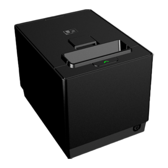
Amber light when the power supply is turn on. Green light when the print is ready to print. ERROR LED (Red) The Error LED indicates an error by showing different blinking patterns. Please refer to Section 13.4 more information. FEED BUTTON Copyright © 2021, Diebold Nixdorf 01750352498B... -
Page 26: Power Button
Pressing this button more than 5 seconds to turn off machine. POWER BUTTON Pressing this button to switch on machine and after installed power connector. Pressing this button more than 5 seconds to turn off machine Copyright © 2021, Diebold Nixdorf 01750352498B... -
Page 27: Connectors
4. [USB Type-B interface connector] A connector, which needs an interface cable connecting the printer to a POS terminal. An USB I/F (V2.0 Full Speed) is need for this connector. Further information can refer to Section 8.5.3 Copyright © 2021, Diebold Nixdorf 01750352498B... -
Page 28: Specification Of Interface & Power Connector
5) Stop Bits : 1 bit or 2 bits 6) Connector Pin Assignment 1Pin 5Pin 6Pin 9Pin Serial I/F connector is 9pin D-SUB Male type connector with the following pin assignments: Pin Number Pin Function Not Used Logic GND Not Used Copyright © 2021, Diebold Nixdorf 01750352498B... -
Page 29: Ethernet Interface
LED indicators defined as follows: Pin Number Pin Function GREEN LINK/ACT LINK YELLOW 100BT Link (up) = LED On; Activity = LED Blink; Link/Act = LED On/ Blink; Speed = LED On (100BASE-T); LED Off (10BASE-T) Copyright © 2021, Diebold Nixdorf 01750352498B... -
Page 30: Power Usb Interface
The Power USB connector on PCB is CONQUEST TECHNOLOGY 351005-7 or FCI 69913-104LF (or equivalent) Connector Pin assignment: Pin 1 Pin 2 Pin Number Pin Function 24V GND + 24V VBUS (+5V) + 24V 24V GND SHELL SHIELD Copyright © 2021, Diebold Nixdorf 01750352498B... -
Page 31: Usb Interface
1) USB Version : Version 2.0 High speed 2) Connector Pin Assignment The USB I/F connector is “B” Plug type for Device function. And “A” Plug type for Host function. Type B connector Pin Position VBUS Shell Shield Copyright © 2021, Diebold Nixdorf 01750352498B... -
Page 32: Power Cable Connector
Resistance Value on Power ID Pin Power 1250 ~ 2125 48 W 2126 ~ 2625 2626 ~ 3415 75 W 3416 ~ 4165 90 W 4166 ~ 8333 110 W <1250 or >8333 75 W Copyright © 2021, Diebold Nixdorf 01750352498B... -
Page 33: Cash Drawer Connector And Pin Assignments
The Cash drawer connector is 6pin RJ12 Shielded type connector with the following pin assignments: Pin Number Pin Function Frame GND Drawer 1 Solenoid Drawer 1 and 2 Status Switch +24 Volts (to Solenoid) Drawer 2 Solenoid Copyright © 2021, Diebold Nixdorf 01750352498B... -
Page 34: Set Up Procedure
*To prevent the emission and receipt of electrical noise, the interface cable must meet the following re- quirements: Fully shielded and fitted with metal or metalized connector housings. Kept as short as possible. Should not be tightly bundled with the power cord. Should not be tied to power line conduits. Copyright © 2021, Diebold Nixdorf 01750352498B... - Page 35 The printer power setting will be adjusted automatically via the power ID resistance measurement. For PUSB, the maximum power available is 75W. The P1200 printer will both be set to the “Auto” power setting. The firmware will measure the resistor and set the power setting according to the table above.
-
Page 36: Setting Up The Printer
11) Check the print quality by performing an Offline Diagnostic. 12) Install the printer driver given into POS terminal. 13) Connect the interface cable to the printer and the POS terminal. Now the printer is ready for printing. Copyright © 2021, Diebold Nixdorf 01750352498B... -
Page 37: Turning Off The Printer
2) LED light will turn off indicates the printer is turned off. 3) To turn on the printer, press the power button again and the LED will light up. 4) Power can be switched off by sending command. Please refer to P1200 programming guide. Copyright © 2021, Diebold Nixdorf... -
Page 38: Installation Procedure
10.1 Connecting the Power Cord and Interface Cable CAUTION Be sure to hold the connector when plugging in or unplugging the power adapter cable. Insert the power adapter cable and the power cord firmly. Copyright © 2021, Diebold Nixdorf 10-1 01750352498B... -
Page 39: Connect To Power Adapter
10.1.1 Connect to Power Adapter Insert the power cable into the power connector. 10.1.2 10.1.2 Connect via standard USB Type-B Cable Connect USB Type-B is to link the printer to the POS Terminal. Copyright © 2021, Diebold Nixdorf 10-2 01750352498B... -
Page 40: Connect Via Option Card (Rs232 & Lan)
Optional metal cover Screw Serial Interface (RS232) Option Connect Secure the cable with screw Secure by stopper Ethernet Interface (LAN) Option Secure Connect with screw the cable Secure by stopper Copyright © 2021, Diebold Nixdorf 10-3 01750352498B... -
Page 41: Connect Via Y-Cable
Option Card screw stopper 10.1.4 10.1.4 Connect via Y-Cable Y-cable is an option to connect power connector and USB Type-B connector to POS terminal. 1) Power Connector 2) USB Type-B 3) 24V Terminal Input Copyright © 2021, Diebold Nixdorf 10-4 01750352498B... -
Page 42: Connecting Via Cash Drawer
2) Connect the drawer cable to the drawer interface connector in the correct orientation. [Drawer interface connector] (6-pin modular connector) A Drawer cable which connects the printer to a drawer is connected to this connector. To this connector, a Diebold Nixdorf drawer can be connected. Further information please refer to Section 9 10.1.6 10.1.6 Interface cable to POS terminal connection position... -
Page 43: Choosing A Location
Compliance with local building codes, electrical codes, and governing laws should take precedence over this set of in- structions. Copyright © 2021, Diebold Nixdorf 10-6 01750352498B... - Page 44 The thickness of the wall should be 10 mm (0.4”) or more. Be sure to use flat head metallic tapping screws. Make sure that the POS printer fix on the mounting heights of 2 meters and below. Wall Mount Min. 10 mm Screw Wall Weight: 1.3kg Copyright © 2021, Diebold Nixdorf 10-7 01750352498B...
- Page 45 *This guide can be printed out in A4 size as a reference for the wall mount. Since printing A4 paper set- tings may vary across different printers, please measure and ensure the distances are the same as the dimensions stated before drilling the wall. Copyright © 2021, Diebold Nixdorf 10-8 01750352498B...
-
Page 46: Loading The Paper Roll
5°C to 50°C. Please do not operate out of range for safe op- Print Head eration. Hazardous moving cut- ter. Keep fingers and other body parts away. Cutter Blades Copyright © 2021, Diebold Nixdorf 10-9 01750352498B... - Page 47 Check for the correct orientation of the paper roll (Thermal coated side facing print head), and load into the paper holder. Pull the receipt until it extends over the paper outlet for about 5 cm. Make sure the paper is laid within the paper guide before closing the top cover. Copyright © 2021, Diebold Nixdorf 10-10 01750352498B...
- Page 48 INSTALLATION PROCEDURE Horizontal Orientation Close the printer top cover gently and printer will automatically perform auto cut. Copyright © 2021, Diebold Nixdorf 10-11 01750352498B...
- Page 49 Insert the 58 mm paper guide to the slots located inside the left side of the printer. Place the 58 mm paper roll inside and close the cover. To remove the paper guide, simply press the latch to the right and pull it out. Copyright © 2021, Diebold Nixdorf 10-12 01750352498B...
- Page 50 INSTALLATION PROCEDURE Latch Copyright © 2021, Diebold Nixdorf 10-13 01750352498B...
-
Page 51: Diagnostics
5. Press or click the Paper Feed button based on the number of clicks associated to your desired option as stated on the Main Menu, then hold the button down for at least one second (2 tone beep sound) to validate. Copyright © 2021, Diebold Nixdorf 11-1 01750352498B... - Page 52 DIAGNOSTICS Service Menu Structure – Main Menu Once it enters offline diagnostic mode, it prints main menu as follow Copyright © 2021, Diebold Nixdorf 11-2 01750352498B...
- Page 53 DIAGNOSTICS Main Menu / Diagnostic Copyright © 2021, Diebold Nixdorf 11-3 01750352498B...
- Page 54 DIAGNOSTICS Main Menu / Configuration / Hardware Copyright © 2021, Diebold Nixdorf 11-4 01750352498B...
- Page 55 DIAGNOSTICS Main Menu / Configuration / Software Copyright © 2021, Diebold Nixdorf 11-5 01750352498B...
- Page 56 DIAGNOSTICS Main Menu / Configuration / Print Options Copyright © 2021, Diebold Nixdorf 11-6 01750352498B...
- Page 57 DIAGNOSTICS Main Menu / Configuration / Print Options Copyright © 2021, Diebold Nixdorf 11-7 01750352498B...
- Page 58 DIAGNOSTICS Main Menu / Configuration / Ethernet Settings Copyright © 2021, Diebold Nixdorf 11-8 01750352498B...
-
Page 59: General Maintenance
The thermal print head does not normally require cleaning if the recommended paper grades be used. If non–recommended paper has been used for an extended period, cleaning the print head with cotton swabs and rubbing alcohol will not be of much benefit. Copyright © 2021, Diebold Nixdorf 12-1 01750352498B... - Page 60 GENERAL MAINTENANCE Print Head Element Copyright © 2021, Diebold Nixdorf 12-2 01750352498B...
-
Page 61: Troubleshooting
Remove the jammed paper. DO NOT USE any sharp implement or tool as these will damage the printer. Re-load the paper roll. Refer to Section 10.3 Close the printer top cover and the printer will be ready to use. Copyright © 2021, Diebold Nixdorf 13-1 01750352498B... -
Page 62: Resetting Cutter Failure Or Jam
When the cutter is jammed, the LED will show Amber color with 3 blinks and Pause for 5 seconds. Open the printer front cover by pulling on the both sides as shown in the figure on the left. Flip to fully open the front cover. Copyright © 2021, Diebold Nixdorf 13-2 01750352498B... - Page 63 TROUBLESHOOTING Flip to open the top cover. Remove any jammed paper and paper roll out from the printer. DO NOT USE any sharp imple- ment or tool as these will damage the printer. Copyright © 2021, Diebold Nixdorf 13-3 01750352498B...
-
Page 64: Common Problems & Solutions
The wall outlet has If it is not a power If not, contact your nearest power problem. failure, check if the company. power is supplied to the AC outlet with another elec- tric appliance. Copyright © 2021, Diebold Nixdorf 13-4 01750352498B... - Page 65 (Paper comes out, Paper Roll inserted Thermal coating Insert correctly the paper roll. Re- but no characters wrongly. should be in contact fer to Section 10.3 are printed on the with printer head. paper) Copyright © 2021, Diebold Nixdorf 13-5 01750352498B...
- Page 66 Make sure the function is enabled function is not en- the POS terminal in the POS terminal. abled in POS terminal NOTE If any problem occurs other than the above, please contact your authorized Diebold Nixdorf representative. Copyright © 2021, Diebold Nixdorf 13-6 01750352498B...
-
Page 67: Led Indication Table
Recoverable error: AMBER 6 Blinks Pause 5 sec- Open the receipt front Section 13.2 Cutter Jam onds cover first, then follow by top cover and check for the cutter. Copyright © 2021, Diebold Nixdorf 13-7 01750352498B... - Page 68 If other LED status except for the above occurs, turn the power supply off, and then re- open. If this does not restore the LED, contact your nearest store representative for assis- tance. Copyright © 2021, Diebold Nixdorf 13-8 01750352498B...
-
Page 69: Appendix
Time out. (link down) : Time out for TCP port close by Link down. (1-120 minutes) Time out. (Idle) : Time out for TCP port close by idle. (1-120 minutes) TCP port : Port number for TCP communication. UDP port : Port number for UDP communication. Copyright © 2021, Diebold Nixdorf 14-1 01750352498B... - Page 70 IP address : IP address for Trap 1 Community name : Community name for Trap1 TRAP 1 : Enable” “Disable” for TRAP 2. IP address : IP address for Trap 2 Community name : Community name for Trap2 Copyright © 2021, Diebold Nixdorf 14-2 01750352498B...
- Page 71 DIEBOLD NIXDORF 5995 Mayfair Road | North Canton, OH 44720 | United States © 2021 Diebold Nixdorf, Incorporated. All Rights Reserved.
Need help?
Do you have a question about the P1200 and is the answer not in the manual?
Questions and answers