
Summary of Contents for Kontron Embedded Computers PxV206
- Page 1 PxV206 – 2U Platform User’s Manual Version 1.01 Kontron Embedded Computers GmbH 0-0096-2594...
-
Page 2: Table Of Contents
Power Supply Unit...................19 Versions of the Power Supply Unit ..............20 Redundant Power Supply Unit ................21 Internal Drive......................24 Backplane ......................24 SBC Board ......................25 Assembly, Disassembly ..................26 Mounting the Rubber Feet ...................26 Accessing Internal Components ................27 PxV206 – 2U Platform – User’s Manual... - Page 3 Technical Appendix – Interfaces ..............41 RS232 ......................... 41 RS422 (COM 2 only) RS485 (COM2 only)..........42 PS/2 Keyboard and Mouse Connector ..............42 Parallel Port......................43 Technical Support ..................... 44 Returning Defective Merchandise ............... 45 PxV206 – 2U Platform – User’s Manual...
-
Page 4: Introduction
Introduction Introduction Kontron Embedded Computers would like to point out that the information contained in this manual may be subject to technical alteration, particularly as a result of the constant upgrading of Kontron Embedded Computers products. The attached documentation does not entail any guarantee on the part of Kontron Embedded Computers with respect to technical processes described in the manual or any product characteristics set out in the manual. -
Page 5: Symbols Used In This Manual
This symbol indicates that the product or parts thereof may be damaged if the corresponding warning notices are not observed. This symbol indicates general information about the product and the user manual. This symbol precedes helpful hints and tips for daily use. PxV206 – 2U Platform – User’s Manual... -
Page 6: Important Instructions
This chapter contains instructions which must be observed when using your PxV206 – 2U Platform. The manufacturers instructions provide useful information on your PxV206. Note on the Guarantee Due to their limited service life, parts which by their nature are subject to a particularly high degree of wear (wearing parts) are excluded from the guarantee beyond that provided by law. -
Page 7: Safety Instructions
PxV206. Observe the warnings and instructions on the device and in the manual. The PxV206 is built and tested by Kontron Embedded Computers in accordance with EN60950/VDE0805 and left the works in a perfectly safe condition. In order to maintain this condition and ensure safe operation, the user must observe the instructions and warnings contained in this manual. - Page 8 Safety Instructions q For PxV206-C only: it is not allowed to remove or to bridge the ATX-plug with the Kontron ATX-extension (a T10A fuse integrated in the 3.3V-circuit of the –48V DC-PSU). q All plugs on the connection cables must be screwed or locked to the housing.
-
Page 9: Operation Of Laser Source Devices
2. Keep electrostatic sensitive parts in their containers until they arrive at static- free stations. 3. Always be properly grounded when touching a sensitive board, component, or assembly. 4. Store electrostatic-sensitive boards in protective packaging or on conductive foam. PxV206 – 2U Platform – User’s Manual... -
Page 10: Grounding Methods
SBC board User manual. The SBC board User manual is included in the delivery. Warning Danger of explosion when replacing with wrong type of battery. PxV206 – 2U Platform – User’s Manual... -
Page 11: Fcc Statement
(EMC Rules 89/336/EWG) and/or the German EMC laws apply. If the user modifies and/or adds to the equipment (e.g. installation of add-on cards), the prerequisites for the CE conformity declaration (safety requirements) may no longer apply. PxV206 – 2U Platform – User’s Manual... -
Page 12: Scope Of Delivery
Power cord (only for AC power supply units) q Rubber feet and screws q Y-adapter cable (PS/2 Keyboard&Mouse) Type Labels and Product Identification The type label of your PxV206 – 2U Platform is attached to the inside of the drive door. Type label Product identification PxV206-A PxV206 –... -
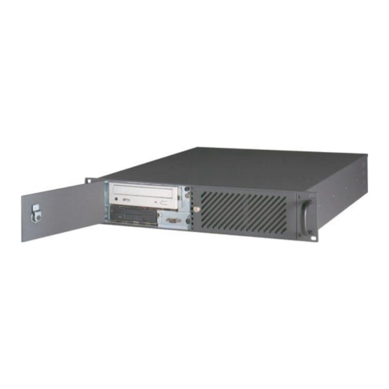
Page 13: Product Description
Product Description Product Description The PxV206 is a 2U (19") system, designed for high-performance applications. The PxV206 - 2U Platform is available in rackmount or desktop options. It includes butterfly-backplane slots with 32-bit PCI design. ® ® Your system can accommodate optionally a Pentium III... - Page 14 Product Description Fig 3: PxV206 – 2U Platform-opened Power Supply Unit (PSU) E-PAC® Floppy-drive (3.5”) Front cooling fans CD-ROM-drive (5.25”) Air filter mat Backplane LED panel SBC board 10 Drive door 11 Fan door PxV206 – 2U Platform – User’s Manual...
-
Page 15: Front Panel
Product Description Front Panel The front panel of PxV206 2U Platform is designed in to versions: q Rackmount q Desktop Fig. 4: Front panel (rackmount version) with closed doors Fig. 4a: Front panel (desktop version) with closed doors Fig. 4b: Front panel (rackmout and desktop version) with opened doors... -
Page 16: Drive Door
The COM1 interface, the PS/2 keyboard and mouse connector, the operating elements (power switch and reset button) and the Floppy- and CD-ROM-drives are located at the front side of the PxV206 – 2U Platform, behind the drive door. Drive Door You can protect the PxV206 –... -
Page 17: Operating Elements
Therefore the power cord and its connectors must always remain easily accessible. Reset Button If your system no longer reacts, you must restart the PxV206. To do this, press the reset button (see fig.: 4b, pos. 10) . When you reset, all data in the main memory are erased. -
Page 18: Front Panel - Leds Status
PSU HDD Activity LED HDD Activity LED (orange) (orange) Not used Not used Not used Not used Not used Not used Not used Not used Not used Not used PxV206 – 2U Platform – User’s Manual... -
Page 19: Rear Panel
(according to 3 5x free slots: the used PSU) 4x PCI and 1x ISA 8 Cover captive knurled screw 4 1x SBC board 9 Card cage captive knurled screw 5 Ground stud PxV206 – 2U Platform – User’s Manual... -
Page 20: Ports On The Rear Side
Platform interfaces may vary depending on the device equipment. Power Supply Unit Each PxV206 – 2U Platform can be equipped optionally depending on the power supply unit (PSU) with an AC–PSU, a DC–PSU or a redundant PSU. PxV206 – 2U Platform – User’s Manual... -
Page 21: Versions Of The Power Supply Unit
Product Description Versions of the Power Supply Unit The power supply unit is placed on the rear side of PxV206 – 2U Platform. Each PxV206 – 2U Platform can be equipped optionally depending on the power supply unit (PSU) with an AC–PSU, a DC–PSU or a redundant PSU. -
Page 22: Redundant Power Supply Unit
2 PSU Power switch 6 Handle 3 PSU Alarm-reset button 7 AC–Power status LED 4 Redundant PSU LED 8 DC–Power status LED During operation all LED control displays of the redundant power supply unit are PxV206 – 2U Platform – User’s Manual... - Page 23 LED start to blink and a beep is audible. The DC–Power status LED from the defective redundant PSU module is not on. The PxV206 2U Platform is continuing to operate with one of the power supply modules. By press of the PSU alarm reset button the beep will be interrupt, but the redundant PSU LED is still blinking till the defective power supply module was changed with a good one.
- Page 24 2. If the system is integrated in a rack, remove at first the unit to have access to the back side of the PxV206 – 2U Platform (loosen the 4 screws for in rack mounting). 3. Locate the defective power supply module by examining the status of DC power status LEDs of the redundant PSU.
-
Page 25: Internal Drive
Fig. 8: Backplane – front side Fig. 8a: Backplane – rear side 1 Power connector for front fans 3 Power connector 2 Connector for main power switch 4 PCI slots 5 PICMG (ISA + PCI) PxV206 – 2U Platform – User’s Manual... -
Page 26: Sbc Board
Your system can accommodate a Pentium III /Celeron - or a Pentium 4/Celeron CPU compatible Single Board Computer (SBC). For detailed information refer to the delivered technical reference manual of the SBC board. PxV206 – 2U Platform – User’s Manual... -
Page 27: Assembly, Disassembly
2. Turn the system upside down. 3. Position the four rubber feet at each corner of the system. 4. Insert one screw inside each rubber foot and secure them to the system. PxV206 – 2U Platform – User’s Manual... -
Page 28: Accessing Internal Components
Failure to take heed of this warning instruction can result in damage to the device. Please consult the documentation provided by the additional card manufacturer for instructions before attempting to install/remove an additional card into/from the PxV206 – 2U Platform. PxV206 – 2U Platform – User’s Manual... - Page 29 2. Remove the captive knurled screw located at the rear of the unit securing the cover. Fig. 10: Removing cover 3. Lift the back of the cover and pull it out. Fig. 11: Removing cover Fig. 12: PxV206 - 2U without cover PxV206 – 2U Platform – User’s Manual...
- Page 30 5. Disconnect all data and power cables from the SBC-card. 6. Pull out and lift the card cage from the housing. Fig. 14: Removing card cage with SBC board 7. Remove/install the additional card from/to the backplane slots. PxV206 – 2U Platform – User’s Manual...
-
Page 31: Start-Up
3. Set the power supply switch to “On”. Do not remove or alter the grounding prong on the power cord. In situations where a two-slot receptacle is present, have it replaced with a properly grounded three-prong grounding type receptacle. PxV206 – 2U Platform – User’s Manual... -
Page 32: Dc-Connection
If you ordered your system with installed operating system, all drivers are installed, corresponding to the ordered system configuration (optional hardware components). Your PxV206 is fully functional when you switch it on for the first time. If you ordered your system without installed operating system, you have to install the operating system and the corresponding drivers for the ordered system configuration (optional hardware components). -
Page 33: Instruction For Installation In A 19" Cabinet
Please observe at that place the details included in the chapter “Accessing Internal Components ”. Before mounting the PxV206 – 2U Platform in a cabinet, you must connect your peripheral devices to the system interfaces. Refer to chapter “Ports on the Back Side ” for the description of the interfaces. - Page 34 The type label is located on the inside of the drive door. For DC power supplies please observe that the supply circuit must withstand loads minimum 25A for the –48V power supply. PxV206 – 2U Platform – User’s Manual...
-
Page 35: Maintenance And Prevention
The air filter mat can be changed even if the system is powered-up. Fig. 18: Dust filter placing 1 Fan door with captive knurled screw 2 Air filter mat 3 Drive door PxV206 – 2U Platform – User’s Manual... -
Page 36: Lithium Battery
4. After cleaning and drying of the air filter mat, put these over the fans, close the fan door and tighten the captive knurled screw. Lithium Battery The SBC board of your PxV206-2U Platform is equipped with a lithium battery. Please observe the safety instruction described in the section „Instructions for the Lithium Battery“. -
Page 37: Main Specifications
AC power switch LED indicators On the front panel: 1x Power-LED 1x HDD-LED On the rear panel (only units with AC redundant PSU): 2x AC Power indicator LEDs 2x DC Power indicator LEDs PxV206 – 2U Platform – User’s Manual... - Page 38 Power on +5 VSB Please take care, that the total PSU output power of your system doesn’t exceed the following value: PxV206-A 250 W PxV206-B 250 W PxV206-C 210 W PxV206-D 210 W PxV206 – 2U Platform – User’s Manual...
-
Page 39: Electrical Specifications
320 W Mechanical Specifications Dimensions Height 2U x 19" (88,9 mm) Width 16.90" (430.2 mm) Depth 18" (457.2 mm) Weight 10 kg approximately (without packaging) Housing steel with zinc plating, ALU front panel black PxV206 – 2U Platform – User’s Manual... -
Page 40: Environmental Specifications
Storage / transit vibration 10 – 58 Hz, – 0.15 mm 58 – 500 Hz, 2.0 G Acoustic noise <50 dB at 1 m in front of the system at full load Protection class IP 52 front side PxV206 – 2U Platform – User’s Manual... -
Page 41: Ce-Directives, Standards And Approvals
EN 50082-1/ EN 61000-6-2 (immunity) EUROPE EN 55022/ B: 1998 (CISPR22) U.S.A. FCC 47 CFR Ch1 § 2.902 Verification Procedure Agency Approvals Standards Designed to meet TÜV EN 60950 Designed to meet UL UL 60950 PxV206 – 2U Platform – User’s Manual... -
Page 42: Technical Appendix - Interfaces
Pin Signal name 9-pin SUB D-plug DCD (Data Carrier Detect) RXD (Receive Data) (Transmit Data) (Data Terminal Ready) GND (Signal Ground DSR (Data Set Ready) (Request to Send) (Clear to Send) (Ring Indicator) PxV206 – 2U Platform – User’s Manual... -
Page 43: Rs422 (Com 2 Only) Rs485 (Com2 Only)
(Receive Data +) RX/TX+ (Receive/Transmit +) (Transmit Data +) not connected not connected not connected PS/2 Keyboard and Mouse Connector Signal name 6-pin Mini-DIN socket Keyboard data Mouse data +5 V Keyboard clock Mouse clock PxV206 – 2U Platform – User’s Manual... -
Page 44: Parallel Port
Technical Appendix – Interfaces Parallel Port Signal name 25-pin SUB D-socket –STROBE DATA0 DATA1 DATA2 DATA3 DATA4 DATA5 DATA6 DATA7 –ACKN BUSY SELECT –AUTOFD –ERROR –INIT –SLCTIN 18–25 PxV206 – 2U Platform – User’s Manual... -
Page 45: Technical Support
Be ready to explain the nature of your problem to the service technician. If you have any questions about Kontron Embedded Computers or our products and services, you may reach us at the aforementioned numbers, or at : www.kontron.com... -
Page 46: Returning Defective Merchandise
5. When returning a Kontron Embedded Computers unit. œ Ensure that the unit is packed in the original box. œ include a copy of the RMA form.
Need help?
Do you have a question about the PxV206 and is the answer not in the manual?
Questions and answers