
Subscribe to Our Youtube Channel
Related Manuals for Endress+Hauser TMD1000 TMD1


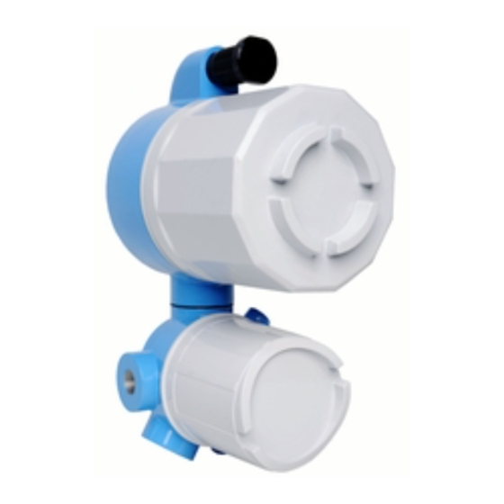
Summary of Contents for Endress+Hauser TMD1000 TMD1
- Page 1 Products Solutions Services BA00429G/00/EN/03.19 71427112 2019-12-27 Operating Instructions TMD1000 TMD1 HHT2 Hand Held Terminal HAND HELD TERMINAL HHT-2- MODE...
- Page 2 TMD1000 TMD1 Order code: XXXXX-XXXXXX Ser. no.: XXXXXXXXXXXX Ext. ord. cd.: XXX.XXXX.XX Serial number www.endress.com/deviceviewer Endress+Hauser Operations App A0023555 Endress+Hauser...
-
Page 3: Table Of Contents
Operation ......16 Endress+Hauser services ....41 Pre-operation and settings . -
Page 4: About This Document
About this document TMD1000 TMD1 About this document Document function These Operating Instructions contain all the information that is required during various phases of the life cycle of the device: from product identification, incoming acceptance and storage, to mounting, connection, operation and commissioning through to troubleshooting, maintenance and disposal. - Page 5 TMD1000 TMD1 About this document Symbol Meaning Phillips screwdriver A0011219 Allen key A0011221 Open-ended wrench A0011222 1.2.4 Symbols for certain types of information Symbol Meaning Permitted Procedures, processes or actions that are permitted Preferred Procedures, processes or actions that are preferred...
- Page 6 About this document TMD1000 TMD1 Symbol Meaning Hazardous area Indicates the hazardous area Safe area (non-hazardous area) Indicates the non-hazardous area 1.2.6 Device symbol Symbol Meaning Safety instructions Observe the safety instructions contained in the associated Operating Instructions. Temperature resistance of the connection cables Specifies the minimum value of the temperature resistance of the connection cables.
-
Page 7: Documentation
• The W@M Device Viewer: Enter the serial number from the nameplate (www.endress.com/deviceviewer). • The Endress+Hauser Operations App: Enter the serial number from the nameplate. 1.3.1 Technical Information The Technical Information contains all the technical data on the device and provides an overview of the accessories and other products that can be ordered for the device. -
Page 8: Basic Safety Instructions
Basic safety instructions TMD1000 TMD1 Basic safety instructions Requirements for personnel The personnel for installation, commissioning, diagnostics and maintenance must fulfill the following requirements: ‣ Be specialists who are trained and have a relevant qualification for this specific function and task. -
Page 9: Operational Safety
Modifications to the device Unauthorized modifications to the device are not permitted and can lead to unforeseeable dangers: ‣ If modifications are nevertheless required, contact your Endress+Hauser Sales Center. Repair To ensure continued operational safety and reliability: ‣ Carry out repairs on the device only if they are expressly permitted. -
Page 10: Product Description
Product description TMD1000 TMD1 Product description Product design All operations on HHT2 are done by using twenty keys on the key pad. The upper four keys are used to turn on/off the power and select modes. Lower sixteen keys are used to select items and input values. -
Page 11: Technical Data
TMD1000 TMD1 Product description Name Descriptions ↑ Device selection screen: The name of the previous device will appear. MODE, ITEM selection screen: The MODE or ITEM screen that is one step smaller than the MODE or ITEM that is being displayed will appear. -
Page 12: Incoming Acceptance And Product
• Do the nameplate data match the ordering information on the delivery note? • If required (see nameplate): Are the Safety Instructions (XA) enclosed? If any one of these conditions is not met, contact your Endress+Hauser Sales Center. Product identification The following options are available for the identification of the measuring device: •... -
Page 13: Manufacturer Contact Address
2 HHT2 nameplate Required contents by a customer (e.g. Tag No.) Order code Meter number Manufacturer contact address Endress+Hauser Yamanashi Co., Ltd. 862-1 Mitsukunugi, Sakaigawa, Fuefuki, Yamanashi, Japan Address of the manufacturing plant: See nameplate. Storage and transport 4.4.1 Storage conditions •... - Page 14 Incoming acceptance and product identification TMD1000 TMD1 NOTICE Risk of injury ‣ Transport the measuring device to the measuring point in its original packaging. ‣ Take into account the center of gravity of the device in order to avoid unintended tilting.
-
Page 15: Electrical Connection
TMD1000 TMD1 Electrical connection Electrical connection Wiring Wiring HHT2 with TMD1:Because HHT2 operation and signals for setting are communicated by a dedicated fiber-optic, a dedicated connecting coupler are mounted on the sending and receiving entry of HHT2 and TMD1. • HHT2 communication has two types of optical communication modules and connection couplers as follows: 1) 2-way, 2-wire, 2) 2-way, single wire. -
Page 16: Operation
Operation TMD1000 TMD1 Operation Pre-operation and settings Check the connection environment between HHT1 and TMD1 before starting TMD1 operation and settings. Because the HHT2 is used for operation and settings of both the TMD1 and the servo level gauge TGM5, follow the instructions in this chapter and set the TMD1 appropriately. -
Page 17: Device Selection
TMD1000 TMD1 Operation Device selection Selecting procedure 1. Turn on the power (after selecting 2-wire on B type). The first screen shows the following: SELECT DEVICE E: 1/F ↓ : NEXT A0038097 2. Using the [↑] and [↓] keys, display the TGM/TM screen and press the [ENT] key. - Page 18 Operation TMD1000 TMD1 Functions Descriptions Temperature measurement 0: Single element average temperature function selection 1: Multi-element average temperature 2: Spot temperature 4 points 3: Spot temperature 1 point Selection of temperature Thermo-A conversion method conversion method 0: Pt100 1: JPt100...
- Page 19 TMD1000 TMD1 Operation Memo No.1 (M00, I12) Digit Descriptions Default memo 4: Gauge status = LEVEL balance flag = Fixed to ON 4 Everything other than 4 is status = LEVEL, balance flag = OFF. 1: Written data from HART CMD#31 64,387 is Written data is output from output to DO port.
- Page 20 MEMO No.2 XXXXXX A0038471 5 Memo No.2 screen display example Memo No.3 (M00, I14) Digit Descriptions Applicable version No. Reserved Reserved Reserved Reserved Reserved Reserved For details on the latest flag for program control, contact your Endress+Hauser Sales Center. Endress+Hauser...
-
Page 21: Mode01 Operation And Display Setting
TMD1000 TMD1 Operation MODE01 Operation and display setting In MODE01, the external device operation can be changed. Functions Descriptions External device ON/OFF External device operation output: 8 points operation External device (The number of point for operation output varies depending on the operation output 1 use of TMD1.) -
Page 22: Mode02 Level And Status
Operation TMD1000 TMD1 Functions Descriptions Gauge operation 0: Liquid surface 1: Hoisting 2: Stop 3: Bottom 4: Operation cancellation 5: Density 6: Interface B: Table C: 10 mm descend D: 10 mm elevation LCD screen selection 0: Home screen 1: Address... -
Page 23: Mode05 Parallel Output
TMD1000 TMD1 Operation MODE05 parallel output When installing parallel output board OUT-3 or OUT-4, the following operation and settings are available. Functions Descriptions Output data and code display LEVEL BCD: Level BCD code output LEVEL-SIC: Level SIC code output TEM-BCD: For temperature BCD code output terminal table, see electrical compartment internal wiring diagram. -
Page 24: Mode07 Spot Temperature Device 1 Point
Operation TMD1000 TMD1 A0038100 6 Alarm 1 to 8 output Alarm output board OUT-2 Terminals Alarm 1 Alarm 1 Common Alarm 2 Alarm 2 Common Alarm 3 Alarm 3 Common Alarm 4 Alarm 4 Common Alarm 5 Alarm 5 Common... -
Page 25: Mode08 Spot Temperature Device 3 Point
TMD1000 TMD1 Operation 6.11 MODE08 spot temperature device 3 point input TMD1 can connect spot temperature devices to up to 3 points.As with the spot temperature device, this mode is only available when Thermo-A is installed. Functions Descriptions No.1 spot GTP: Spot temperature device 1 measurement value NTP: Measurement value ±... -
Page 26: Mode10 Single-Element Average Temperature
Operation TMD1000 TMD1 Functions Descriptions Switch interval A0038101 7 Bottom level value n: Element interval B: Bottom level value (The level at which the first point element is in the liquid) When "B" is set in ITEM03 and "n" is set in ITEM04 = level value: Up to n + B <... -
Page 27: Mode11 Analog 4 To 20 Ma Output (No. 1)
TMD1000 TMD1 Operation Functions Descriptions No.4 element data GTP: No. 4 element measurement value NTP: No. 4 element calculation value ± Temperature correction value No.5 element data GTP: No. 5 element measurement value NTP: No. 5 element calculation value ± Temperature correction value No.6 element data... -
Page 28: Analog 4 To 20 Ma Output No. 2
Operation TMD1000 TMD1 Functions Descriptions Set level ZERO Sets the level value at 0 % output Set temperature output 0: NON 1: Set as YES (set with "1" and "ENT") When selecting level output in ITEM02, the temperature output will be automatically canceled. -
Page 29: Mode13 2-Way, 2-Wire Transmission
TMD1000 TMD1 Operation Functions Descriptions Configure and adjust current 0: INS (outputs the measurement value) output 1: AJ-4 (4 mA output) 2: AJ-20 (20 mA output) The fixed values of 4 mA and 20 mA are output from 1 and 2. -
Page 30: Mode15 Ffi Transmission Output
Operation TMD1000 TMD1 6.18 MODE15 FFi transmission output Functions Descriptions FFi communication address Set FFi communication address 00 to 07. setting FFi level transmission range 0: FFi level transmission method (± 32 767 mm) setting 1: SAKURA level transmission method (0 to 65 535 mm) 6.19... -
Page 31: Mode31 Nmt: V1 (Element Temperature)
TMD1000 TMD1 Operation 6.20 MODE30 NMT: V0 (temperature value) setting Functions Descriptions Average liquid temperature Average value of element temperature in liquid Calculation is not possible: All elements are open in liquid; however, if all elements are exposed, the gas temperature will be displayed. -
Page 32: Mode33 Nmt: V3 (Element Position)
Operation TMD1000 TMD1 Functions Descriptions Element No.14 temperature Same as above Element No.15 temperature Same as above Element No.16 temperature Same as above Select averaging method 0: Standard. Divides the total value of each element temperature with the number of elements. -
Page 33: Mode35 Nmt: V5 (Water Scale Temperature)
TMD1000 TMD1 Operation Functions Descriptions Element switching point When the liquid level increases, add only the increased level to the hysteresis switching point, and when the level decreases, subtract only the decreased level, to limit element switching due to waves in the liquid, etc. -
Page 34: Mode36 Nmt: V6 (Water Scale And Power Supply) Adjustment
Operation TMD1000 TMD1 Functions Descriptions Water scale offset This value is used for the following formula to find water scale. (correction value) Water scale = (measurement frequency - frequency of all oil in tank) / probe coefficient Span + Water scale offset... - Page 35 TMD1000 TMD1 Operation Functions Descriptions Element temperature Temperature for specified element This is used to calculate liquid average temperature or gas average temperature as element temperature. Applicable devices: 183, 184, 186 (see MODE30 device types) Element position Element position for specified element Element position for unequal interval can be adjusted using this function.
-
Page 36: Mode38 Nmt: V8 (Device) Setting
Operation TMD1000 TMD1 6.28 MODE38 NMT: V8 (Device) setting Functions Descriptions Error information 0: No error 1: Common line open 3: No. 1 element open 4: No. 1 element short 5: No. 2 element open 6: No. 2 element short 7: No. -
Page 37: Mode39 Nmt: V9 (Device) Setting
Polling address Short address for HART communication (HART communication) Applicable devices: 183, 184, 185, 186 (see No. 10 below) Manufacture ID 17: Code for Endress+Hauser (HART communication) Applicable devices: 184, 186 (see No. 10 below) Software version Displays the software version Applicable devices: 183, 184, 185, 186 (see No. -
Page 38: Diagnostics And Troubleshooting
Diagnostics and troubleshooting TMD1000 TMD1 Diagnostics and troubleshooting General troubleshooting 7.1.1 Error Message Error codes Displays Items Error descriptions Causes 0000 0000 0000 0001 HART No response Communication Communication 0000 0000 0000 0010 NMT device Error codes 0000 0000 0000 0100... - Page 39 TMD1000 TMD1 Diagnostics and troubleshooting MODE No. XX xxx # XXXXXXXXX ? A0038466 8 Battery mark Replacement procedure 1. Remove the screws (4 pcs.) and HHT2 rear cover. /Handy terminal Order code Serial no. HHT-2 Ex Proof model :...
-
Page 40: Firmware History
Diagnostics and troubleshooting TMD1000 TMD1 3. Remove the battery case, then push "OPEN" on the battery cover and slide the cover to the allow direction to open it. OPEN A0038469 11 Battery replacement 2 4. Replace the batteries with new ones. Be sure to set the batteries in correct direction + and -. -
Page 41: Repair
General information on repairs 8.1.1 Repair concept The Endress+Hauser repair concept assumes that the devices have a modular design and that repairs can be done by the Endress+Hauser Service Department or specially trained customers. Spare parts are included in appropriate kits. They contain the related replacement instructions. -
Page 42: Return
The device must be returned if it is in need of repair or a factory calibration, or if the wrong device has been delivered or ordered. According to legal regulations, Endress+Hauser, as an ISO-certified company, is required to follow certain procedures when handling returned products that have come into contact with measured materials. -
Page 43: Index
TMD1000 TMD1 Index Index Symbols Application ....... . . 8 Safety Instructions Basic . - Page 44 www.addresses.endress.com...
Need help?
Do you have a question about the TMD1000 TMD1 and is the answer not in the manual?
Questions and answers