Table of Contents
Advertisement
Quick Links
Advertisement
Table of Contents

Related Manuals for Medmont E300


Summary of Contents for Medmont E300
- Page 1 MEDMONT E300 CORNEAL TOPOGRAPHER USER MANUAL Medmont International Pty Ltd Unit 1, 170-180 Rooks Rd, VERMONT VICTORIA 3133, AUSTRALIA Phone: 61-3-9874-1388 Fax: 61-3-9874-1488 e-mail: help@medmont.com.au Web: www.medmont.com.au Doc No: P-1470 V2.1 © MEDMONT May 2011...
-
Page 3: Table Of Contents
INTENDED PURPOSE ................... 2 Power Connection ..................2 Standard E300 Accessories ..............3 Optional System Accessories available from Medmont ......4 Spare Parts ....................4 Consumables .................... 4 The E300 Software................... 5 Software Conventions 5 WARRANTY ....................6 ... - Page 4 Cartesian Grid Polar Grid Keratometrics Cross Section Attributes Annotations Readout Text Data Blocks 33 Sim K e (Eccentricity) Values p Values Q (Asphericity) Medmont E300 Corneal Topographer...
- Page 5 Zooming and Panning ................42 Using the Mouse to Pan and Zoom 42 Using the Section Display ..............43 Displaying Analysis Details ..............44 Exam Filters ................... 45 Sorting E300 Exams................46 E300 Attributes ..................47 Arrange Attributes 47 Custom Attributes 48 ...
- Page 6 Changing the Calibration Used for an Exam 63 Categories 63 Deleting Exams, Prescriptions and Calibrations ........64 CALIBRATING THE E300 ................65 Capturing Calibration Images ............... 65 Checking the Current Calibration ............66 Recalibrating the Instrument ..............66 ...
-
Page 7: Manual Conventions
A small glossary is included for terminology that either originated with Medmont, or is common usage in corneal topography. It also includes some common terms where they apply to Medmont equipment. It is not a definitive glossary of corneal topography. -
Page 8: Intended Purpose
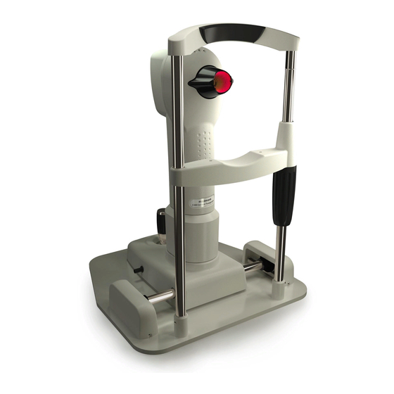
The clinical applications include providing measured corneal data for contact lens fitting, refractive surgery, orthokeratology and general assessment of the corneal surface. The E300 shall only be used as described in this manual and only for the intended purpose. Figure 1. The E300 Instrument. -
Page 9: Standard E300 Accessories
Please make sure that your system is set up correctly in the right environment. When used in a Patient Environment, the E300 equipment must be powered via a protective isolation transformer, compliant to the governing medical standard IEC60601-1 or UL2601/CSA22.2#601-1. -
Page 10: Optional System Accessories Available From Medmont
2 chinrest pins, 1 box chinrest paper, 2 Caution labels (EN/IEC60950 equipment), Hospital Grade Power Cord (for North America only). • User Manual including installation Guide. • Medmont Studio Software on CDROM medium. • Calibration file on CDROM. Optional System Accessories available from Medmont •... -
Page 11: The E300 Software
Intended Purpose The E300 Software The E300 Software is part of the Medmont Studio integrated software environment. See the Medmont Studio documentation for help on installing and using the Medmont Studio environment. Software Conventions The term Application Button refers to the circular button in the top left of the menu bar. -
Page 12: Warranty
Warranty 3. Warranty The E300 Corneal Topographer device has been manufactured with all due care and subjected to stringent testing before leaving the factory. The Topographer is guaranteed for 12 months from the date of purchase as evidenced by the invoice. During this warranty period Medmont International or an authorised agent will repair or replace all defective parts free of charge. -
Page 13: Important Facts
Important Facts 4. Important Facts The E300 Corneal Topographer is a highly accurate measuring instrument. It measures and maps the surface of the human cornea and represents the results in various quantities and output forms that can be applied in various medical applications. -
Page 14: Explanation Of Symbols And Labels
E300. IPX1 Protection against ingress of water. Power Indicator on rear side of unit. The E300 is powered if indicator is illuminated green, unpowered if un-illuminated. This label is found on the PC port insulation plugs. -
Page 15: Regulatory Information
Accuracy and Calibration The E300 is delivered to the end user quality tested, calibrated and as per specifications. It is not the responsibility of Medmont International to guarantee or police the accuracy of this instrument after delivery. The E300 is delivered with a calibrated and certified test object with an accuracy based on the national standard. -
Page 16: Radiation
Interference Strong electromagnetic interference from other unprotected devices may affect the performance or results of the E300. If the use of such devices with high electromagnetic emissions cannot be avoided, do not use the E300 and the device simultaneously. -
Page 17: Installation
Cover any open PC communication ports that have accessible conductors with dummy plugs if used in a patient environment. Instrument Environment The E300 is highly precise measuring equipment and must be located in a suitable and clean environment. The environmental requirements for the E300 are: Room temperature: +10°C to +40°C... -
Page 18: Software Installation
Strong surrounding electromagnetic fields may affect performance and results of the E300. It is recommended that the E300 be set up on the Medmont Automatic Table TE300 for optimum positioning flexibility and stability. Customers using their own table should ensure the linear guides are assembled parallel and positioned as per Figure 3, and that the table is adequately secured. -
Page 19: Running The Software
Installation The E300 software is a part of the Medmont Studio software package. A single CDROM is supplied with installation software for all Medmont Studio components. • Insert the Medmont Studio CDROM and run the Setup program found in the root directory. Select the E300 component when asked which components to install. -
Page 20: Registering The E300
Installation 3. Ensure that the item MEDMONT E300 USB appear in the list of imaging devices as per the screen in Figure 1 Figure 4. Device Manager showing a successful connection to the Medmont E300 Corneal Topographer If the E300 Corneal Topographer does not appear as per these instructions refer to the troubleshooting section in this manual for suggested solutions. -
Page 21: Disconnecting The E300 Instrument
If there’s more than one instrument listed, you will need to install the E300 instrument that will be used for E300 exams. This can be done by selecting a particular instrument, then clicking the Install button. -
Page 22: Testing A Patient
Medmont E300 instrument. Patient Selection The recommended practise is to have a patient selected before starting to capture and analyse an exam. Figure 5 shows the Medmont Studio initial display with a patient selected in the explorer pane. Figure 5. Patient selection. -
Page 23: Capturing Patient Exams
Click on the Home > New Exam > Corneal Topography button to display the E300 Capture View (see Figure 7). The red illumination rings inside the E300 cone should turn on. Ensure the Normal option is selected in Home > Capture Mode > Normal (Figure 6). - Page 24 Select the eye to be examined in the Exam Details box (the right eye is the default). The focussing window shows live video from the E300. The green and red target overlaid on the focussing window provides three-dimensional centring and focussing information. The green crosshair indicates the keratoscope axis.
-
Page 25: Saving The Best Image
Testing a Patient Using the joystick, position the E300 relative to the patient’s eye so that the reflection of the Placido rings is centred on the green crosshair, and the red bar is over the horizontal green line. Once this is achieved, the software automatically captures the best set of images and displays them in the image windows along the top of the View pane, with the best images to the right. -
Page 26: Capturing Video
Viewing Exam Results on page 23). Capturing Video The E300 can capture video at frame rates of up to 25 frames per second (fps). Click on the Home > New Exam > Corneal Topography button display the E300 Capture View (see Figure 7). The red illumination rings inside the E300 cone should turn on. -
Page 27: Alternate Methods Of Patient Selection
If a patient is currently selected her name is displayed in the caption bar of the window. Click on the Home > Patient > Select button to bring up the Find Patient dialog (see Figure 11). Medmont E300 Corneal Topographer... - Page 28 Testing a Patient Figure 11. Patient Selection Dialog. Select a patient from this list and click OK. You can now save an exam against this patient. Medmont E300 Corneal Topographer...
-
Page 29: Analysing And Viewing Exam Results
Analysing and Viewing Exam Results 7. Analysing and Viewing Exam Results The E300 software provides a variety of ways in which to view exam results. The Exam View mode controls how selected exams are displayed (see Setting the Exam View Mode on page 24 ). For each of these modes you can set the type of data to display (see Changing the View Settings on page 26 ), and the color mapping (see Setting Elevation Map Options on page 36). -
Page 30: Setting The Exam View Mode
Setting the Exam View Mode The View Mode controls how the selected Patient Exams are displayed. You select the View mode from the top of the patient tree. Figure 13 Possible E300 display mode options. The selections for the various modes are: Details View Click on the button at the top of the patient tree. -
Page 31: Combination View
Compare View Click on the button from the top of the patient tree. This view displays two selected Patient Exams and the difference between them. Use this view to observe changes over time and healing patterns. Medmont E300 Corneal Topographer... -
Page 32: Changing The View Settings
Figure 17. Map view settings dialog. These options are applied to the image as you change them and are immediately visible. You can click at any time on the Display > Defaults > Reset button to restore the software defaults. Medmont E300 Corneal Topographer... -
Page 33: Map Types
Displays the local paraxial power of the surface in Diopters. Elevation Map Displays the distance from a specified best- fit sphere to the surface in microns. Positive values indicate the surface is above the best- fit sphere. Medmont E300 Corneal Topographer... -
Page 34: Height Map
Height Map - Zernike Fit A decomposition of the height data in terms of the Zernike components. These can be added or removed from the display by selecting Data Setting… button underneath the Map drop-down list. Medmont E300 Corneal Topographer... -
Page 35: Height Map - Zernike Residual
Refractive Power Map Displays the true refractive power of the surface in Diopters. Tangential Curvature Map Displays the local curvature of the surface in Medmont E300 Corneal Topographer... -
Page 36: Wavefront Error Map
These views are selected by clicking the appropriate button: Plan – 2-dimensional Perspective – 3-dimensional A 3-dimensional exam view is displayed without the eye image. An example for the same image used above is shown in Figure 18. Medmont E300 Corneal Topographer... - Page 37 (see Setting the Exam View Mode on page 24). Activating one of the four sub-views by clicking on it will allow that sub-view to be customised using the options on the Display ribbon bar tab. Medmont E300 Corneal Topographer...
-
Page 38: Image
A white Section indicator line is displayed over the color map to indicate the source of the cross section. The Section line has three handles, which allow you to rotate and translate the line (see Using the Section Display on page 43). Medmont E300 Corneal Topographer... -
Page 39: Attributes
(respectively). Unit of measurements can be specified from the Sim K units drop down box on the Display tab. Medmont E300 Corneal Topographer... -
Page 40: Sim K
Flat (in blue) axes of the eye, and the corneal cyl ΔK (formerly dk). The parameters include a number of changes from earlier versions that bring the E300 terminology more into line with current use. Among others, E Values are now referred to as e for eccentricity, corneal cyl was previously dk and is now ΔK, shape factors are now called e... -
Page 41: Values
How is the ellipse approximated? Medmont computes the unique ellipse that gives the same axial curvature at a specified chord and apical curvature as the actual eye. In practice this method gives repeatable and reliable shape factor readings. -
Page 42: Color Map Opacity
The Inner Radius defines the size of the annulus inside diameter, and thus defines how much of the central eye surface will be ignored. The Medmont E300 Corneal Topographer... -
Page 43: Setting Up The Color Key
(light green). Standard Color Keys The E300 provides a number of predefined color keys for each map type. Medmont E300 Corneal Topographer... -
Page 44: Color Key Descriptions
Normalized Power – A normalized scale for mapping refractive power values in Diopers to a color scale using a linear Color Key such that it’s upper and lower bounds correspond to the limits of the data in the image. Medmont E300 Corneal Topographer... - Page 45 The current Color Key type is displayed at the bottom left of each map display. The keys are selected from the drop down box that appears by clicking on the down arrow beside the text (see Figure 22). Medmont E300 Corneal Topographer...
-
Page 46: Custom Color Keys
Color Key. The Normalized setting linearly re-scales the current Color Key so that its upper and lower bounds correspond to the limits of the data in the image. An example is shown in Figure 24 for the Universal Standard Scale key. Medmont E300 Corneal Topographer... -
Page 47: Difference Color Keys
Normalized color key of the same image showing the color key re-mapped from the standard –100 to +100 to cover just the image data range. Note that the scale will always be symmetrical about zero, even if the data is not. Medmont E300 Corneal Topographer... -
Page 48: Zooming And Panning
Zoom mode, click on the point in the image that you wish to zoom in on. The image will continue to zoom in while the left mouse button is held Medmont E300 Corneal Topographer... -
Page 49: Using The Section Display
If you need to see the entire graphic, use the Normalize button in the color key Custom Settings dialog (see Custom Color Keys on page 40). Medmont E300 Corneal Topographer... -
Page 50: Displaying Analysis Details
Similarly, clicking and dragging the Chord slider will move the cross along the Section indicator line. Alternatively, with this dialog displayed, dragging the Section indicator line Medmont E300 Corneal Topographer... -
Page 51: Exam Filters
Exam Filters Exam filters allow you to restrict which Exams are shown in the Explorer pane. Select the E300 Exams tab at the bottom of the Explorer pane and the select the Filter entry as shown in Figure 28. Figure 28. E300 exam filter selection. -
Page 52: Sorting E300 Exams
Figure 29. E300 exam filter selection dialog. Sorting E300 Exams The E300 Exams displayed in the Explorer pane can be sorted by any of the column headings when the E300 Exams tab is active. Click on the heading for any column and the display will show exams sorted by entries in that column. -
Page 53: E300 Attributes
HVID – this is a measure of the horizontal visible iris diameter. You will need to manually define an iris for this attribute to be defined. Figure 31. E300 attributes window. Arrange Attributes The Arrange Attributes dialog shown in Figure 32 controls which attributes are displayed and the order in which they are displayed. -
Page 54: Custom Attributes
Some statistics are not applicable to all exam types. There will also be some pre-Medmont Studio exams that will be missing the later statistics. These attributes are normally shown in italics with no value. By un-checking the Show Undefined Attributes check box these particular attributes will automatically be removed from the list. - Page 55 “°” text in the Units box to “rad”, and change the Decimal Places setting from “1” to “3”. At this point the expression editor should look like Figure 35. Medmont E300 Corneal Topographer...
-
Page 56: Creating An Idealized Eye
° by holding down the Alt key and typing 167 on the numeric keypad. Creating an Idealized Eye Ideal Eye allows you to create an idealized symmetric, toric ellipsoidal surface based on the average values of the currently selected Medmont E300 Corneal Topographer... -
Page 57: Adding Annotations
The chord used is that set for measuring shape factors in the E300 Options dialog (see Setting Elevation Map Options on page 36). -
Page 58: Callout Annotations
These are Circle, Ellipse, Rectangle and Square, with an additional three tools for drawing polygonal Areas. The shapes are shown in the Medmont Studio user manual. You can also draw a ruler that resembles a Callout annotation where the callout is automatically the current length of the ruler in mm. -
Page 59: Editing And Deleting Annotations
Removing Artefacts It is now possible to remove known artefacts from E300 maps. If tear film or other artefacts are present on the eye being examined, they can be removed using this tool. - Page 60 Analysing and Viewing Exam Results Select an E300 exam from the tree view and click on the Analysis > Data Points > Edit button . If raw analysis data is not already present, the exam will be re-analysed. This will enable the eraser tool: Figure 37.
-
Page 61: Printing The Exam Results
Click on the Application button and select Print to print the displayed exams immediately or alternatively select the Print Preview to adjust titles and margins and view output before printing (see the Medmont Studio documentation for more detail). Printing to a color printer provides a concise summary of the exam (see Figure 39). -
Page 62: Exporting The Analysis
Figure 39. Standard exam printout in Print Preview. Exporting the Analysis The E300 software provides the facility to dump raw topography data for the selected exam to a set of text files. This data can then be imported and manipulated by external software and tools. - Page 63 Each line of the file contains the data for a single spoke (centred at the keratometric axes) with data points for each ring. Missing data is indicated by zero values. There are 300 spokes each with 32 rings. Medmont E300 Corneal Topographer...
-
Page 64: Fitting Contact Lenses
Fitting Contact Lenses 8. Fitting Contact Lenses The E300 software provides a simulated fluorescein display for evaluating the fit of RGP contact lenses (see Figure 40). This is a simulation and should only be used as a guide to the expected fit. Note the T and N letters denote the Temporal and Nasal orientation of the lens. -
Page 65: Restricting The Available Designs
The dialog is displayed when creating a new contact lens. You can also use it to change the design or refraction for an existing contact lens by clicking on the Display > Design > Change button. Medmont E300 Corneal Topographer... -
Page 66: Editing The Lens Design
Figure 43. ACL TriCurve contact lens designer dialog. Enter values in the numeric text boxes by clicking the spin-buttons or using the keyboard (see Software Conventions on page 5). Medmont E300 Corneal Topographer... -
Page 67: Moving The Contact Lens
Display > Show/Hide > Lens Parameters checkbox.. Contact View Settings A number of parameters specific to the lens design are available on the Display > Show Hide ribbon bar group as shown in Figure 44. Medmont E300 Corneal Topographer... -
Page 68: Printing The Contact Lens Design
Application Button > Print, then click OK. Alternatively, navigate to Application Button > Print Preview to adjust titles and margins and view output before printing. A typical fluorescein print is shown in Figure 45. Figure 45. Example fluorescein printout in Print Preview. Medmont E300 Corneal Topographer... -
Page 69: Managing Exams And Calibrations
Exam is captured. It is possible to change this using the Calibration drop- down box. Usually the only reason for doing this would be if you discovered that the instrument has gone out of calibration (see Calibrating the E300 on page 65). Once you have re-calibrated the instrument select the Patient Exam that you wish re-analyse, and select the new calibration using the Calibration drop-down box. -
Page 70: Deleting Exams, Prescriptions And Calibrations
You cannot delete a calibration that is used by a patient exam. In general it is not a good idea to delete calibrations. Select the item(s) to be deleted in the Explorer pane. Then click on Home > Exam > Delete. Medmont E300 Corneal Topographer... -
Page 71: Calibrating The E300
To start, mount the calibration object in the E300 chin rest. There is a slot beneath the top rail of the chin rest and a 4mm hole facing the E300. Hold the calibration object with the ball facing the E300, and slide the tab with the threaded hole into this slot from beneath. -
Page 72: Checking The Current Calibration
Figure 48. Verifying the Current Calibration Recalibrating the Instrument If you elect to recalibrate the instrument the Calibration Wizard will run the calibration process. It displays the current status of the calibration (see Medmont E300 Corneal Topographer... - Page 73 Figure 49). The calibration will automatically stop once the error is sufficiently low. Figure 49. Recalibrating the Instrument Calibration of the E300 involves analysing and adjusting over 80 software parameters to match the exact physical dimensions of the instrument. Consequently, depending on the speed of the PC, calibrating a new instrument may take several hours.
-
Page 74: Menu And Icon Reference
Menu and Icon Reference 11. Menu and Icon Reference The E300 software component adds the following types of icons to the Medmont Studio Explorer pane: E300 Exam – displayed under Patient nodes in the Tree and E300 panes. Idealized Eye – displayed under Patient nodes in the Tree and E300 panes. -
Page 75: Configure Tab Items
Shape Factors, the height and Wavefront errors which affects the attribute values. Analysis Tab Items The Analysis tab is added by the E300 component. It is only displayed when a Patient Exam is selected: Reset – clears the analysis of the selected E300 Exams. This forces the software to re-analyse the selected exams. -
Page 76: Display Tab Items
Menu and Icon Reference Display Tab Items The Display tab is added when a graphical E300 view is selected or taking an E300 exam (see Setting the Exam View Mode). Reset – resets the zoom and pan to the default settings for the displayed view. - Page 77 Cross Section – Toggles on or off a cross-section of the displayed data in a tabbed window below the colour map. A white indicator line is displayed over the colour map to indicate the source of the cross section. Medmont E300 Corneal Topographer...
-
Page 78: Edit Tab Items
Bottom – Drop-down controls for the bottom left hand side data block (see Text Data Blocks on page 33). Edit Tab Items The Edit tab is added by the E300 component. It is only displayed when a Patient Exam is selected: Text – add a text annotation to the image. -
Page 79: Glossary Of Terms
Inferior/Superior (IS) index: The IS is the difference (measured in diopters) between the average inferior power and the average superior power. Installed instrument: The instrument (specified by its serial number) that the software expects to use for image capture. Medmont E300 Corneal Topographer... - Page 80 The difference between the predicted power and the actual power is averaged over the central 4mm chord area. The SRI is then given by: × log( ZERO POINT SCALING FACTOR − edictedP ActualP Medmont E300 Corneal Topographer...
- Page 81 ZERO_POINT = 0.90 Note: SCALING_FACTOR and ZERO_POINT values are chosen to given equivalence with the original TMS SRI values. Tear-Film Clearance (TFC): The distance between the surface of the eye and the contact lens at a point. Medmont E300 Corneal Topographer...
-
Page 82: Cleaning And Maintenance
Grease absorbing micro fibre cleaning cloth (e.g. Luminex). • Non-smear optics cleaner. The cone assembly is made of polymer products. This means the cone is sensitive to mechanical surface damage (scratches, dents) and may not be chemically resistant to certain solvents. Medmont E300 Corneal Topographer... -
Page 83: Calibration Object
The following guide is an aid for the user to help identify, describe and remove certain errors. Problem Comment Action No video image 12V indicator light is OFF Instrument ON/OFF switch on? Check power adaptor is fully plugged in. Return back to supplier for repair. Medmont E300 Corneal Topographer... - Page 84 If no: Check RH channel from front (look in sideways into small rectangular opening). Is blue light on? If yes: Has instrument been subjected to excessive shock, vibration or impact? If yes: check calibration and recalibrate if necessary. Medmont E300 Corneal Topographer...
- Page 85 One or more images too far off centre One or more of the calibration balls not clean Profile optics misaligned Dirt on profile optics Too much stray light in image Too much movement in image Illumination defect Medmont E300 Corneal Topographer...
-
Page 86: Specifications
100 – 240 V AC 10 VA (PC not included) PC and mains powered Compliance with EN/IEC60950 peripherals: CISPR22 EN/IEC55022 (See Medmont Studio manual) Printer: Bubblejet/Laser Color/ Monochrome Back Up: CDROM or DVD burner Operating conditions: +10° to +40°C max 80% relative humidity Medmont E300 Corneal Topographer... - Page 87 Specifications Isolation Transformer Compliance with EN/IEC 60601-1 National electrical safety regulations Transport/Storage Conditions: -15° to +40°C 10% to 95% relative humidity 500 to 1060 hPa Medmont E300 Corneal Topographer...
-
Page 88: Representatives
The EU Authorised Representative: BiB Ophthalmic Instruments Unit 8, The Orbital Centre, Cockerel Close Gunnels Wood Road Stevenage, Hertfordshire SG1 2NB England Tel: 0044 (0)1438 740823 Fax: 0044 (0)1438 356093 Your Local Medmont Authorised Agent is: Medmont E300 Corneal Topographer...
Need help?
Do you have a question about the E300 and is the answer not in the manual?
Questions and answers