Table of Contents
Advertisement
Quick Links
Advertisement
Table of Contents

Related Manuals for Medmont E300


Summary of Contents for Medmont E300
-
Page 1: User Manual
MEDMONT E300 CORNEAL TOPOGRAPHER USER MANUAL Medmont International Pty Ltd 5/56 Norcal Rd NUNAWADING VICTORIA 3131, AUSTRALIA Phone: 61-3-9259-0800 Fax: 61-3-9877-6431 e-mail: help@medmont.com.au Web: www.medmont.com.au Doc No: P-1470 V2.7 © MEDMONT Sep 2015... -
Page 3: Table Of Contents
Running the Software ................. 18 Connecting the E300 instrument ............18 Connecting the USB Video Converter box ......... 18 Checking the E300 instrument is connected ........18 Installing the E300 ................. 20 Disconnecting the E300 instrument ............20 Disconnecting the USB Video Converter box: ........20 Disconnecting from the Mains Power outlet ........ - Page 4 Custom Colour Scales ................ 63 Difference Colour Scales..............64 Displaying Analysis Details ..............64 Exam Filters ..................66 Sorting E300 Exams ................66 Creating a Composite Exam ..............67 Creating an Idealized Eye ..............67 Adding and Editing Annotations ............68 Pupil and Iris Attribute Annotations ...........
- Page 5 Changing the Calibration Used for an Exam ........78 Categories ................... 79 Deleting Exams, Contact Lenses and Calibrations ........ 79 10. CALIBRATING THE E300 ................80 Choosing the Video Source ..............80 Capturing Calibration Images ..............81 Checking the Current Calibration ............82 Recalibrating the Instrument ..............
- Page 6 Medmont E300 Corneal Topographer...
-
Page 7: Manual Conventions
A small glossary is included for terminology that either originated with Medmont, or is common usage in corneal topography. It also includes some common terms where they apply to Medmont equipment. It is not a definitive glossary of corneal topography. -
Page 8: Intended Purpose
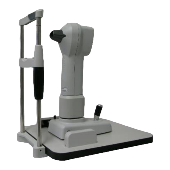
The clinical applications include providing measured corneal data for contact lens fitting, refractive surgery, orthokeratology and general assessment of the corneal surface. The E300 shall only be used as described in this manual and only for the intended purpose. Figure 1. The E300 Instrument. -
Page 9: Power Connection
Power Connection A typical power connection between the various units is shown in Figure 2. Figure 2. Typical Power Connection. For information on purchasing an isolation transformer, please contact Medmont for a list of recommended suppliers. Medmont E300 Corneal Topographer... -
Page 10: Standard E300 Accessories
Software license activation number Optional System Accessories available from Medmont DV2000 Diagnostic Video Imaging software module Electric Table Converter box upgrade kit Reverse adaptor cable Replacement slide rail replacement kit for E300, E300 W Medmont E300 Corneal Topographer... -
Page 11: Spare Parts
Main Cable Replacement Kit PN: 2097 Consumables Chinrest Paper models E300, E300W-pack 300 pc models E300 U, E300 USB - pack 300 pc Cotton swabs Tapered double headed on 150mm wooden sticks. Cat No MG 8112-100 bag of 100... -
Page 12: The E300 Software
Intended Purpose The E300 Software The E300 Software is part of the Medmont Studio integrated software environment. See the Medmont Studio documentation for help on installing and using the Medmont Studio environment. Software Conventions When referring to menu selections, the notation Home > Patient > New means click on the Home ribbon bar tab, then look for the Patient group on the ribbon bar and click on the New icon. -
Page 13: Warranty
Warranty 3. Warranty The E300 Corneal Topographer device has been manufactured with all due care and subjected to stringent testing before leaving the factory. The Topographer is guaranteed for 12 months from the date of purchase as evidenced by the invoice. During this warranty period Medmont or an authorised agent will repair or replace all defective parts free of charge. -
Page 14: Important Facts
Important Facts 4. Important Facts The E300 Corneal Topographer is a highly accurate measuring instrument. It measures and maps the surface of the human cornea and represents the results in various quantities and output forms that can be applied in various medical applications. -
Page 15: Regulatory Information
Important Facts Power Indicator on rear side of unit. The E300 is powered if indicator is illuminated green, unpowered if un-illuminated. Warning: Remove Mains and USB Cord Before Opening Enclosure! WARNING: USA and Canada; Grounding reliability can only be achieved to a receptacle marked “HOSPITAL ONLY”... -
Page 16: Classification
Accuracy and Calibration The E300 is delivered to the end user quality tested, calibrated and as per specifications. It is not the responsibility of Medmont to guarantee or police the accuracy of this instrument after delivery. The E300 is delivered with a calibrated and certified test object with an accuracy based on the national standard. - Page 17 Guidance and manufacturer’s declaration – electromagnetic immunity The E300 Corneal Topographer is intended for use in the electromagnetic environment specified below. The customer or the user of the E300 USB Corneal Topographer should assure that it is used in such an environment.
- Page 18 RF transmitters, an electromagnetic site survey should be considered. If the measured field strength in the location in which the E300 USB Corneal Topographer is used exceeds the applicable RF compliance level above, the E300 USB Corneal Topographer should be observed to verify normal operation.
-
Page 19: Electromagnetic Emissions
The E300 USB Corneal Topographer is intended for use in an electromagnetic environment in which radiated RF disturbances are controlled. The customer or the user of the E300 USB Corneal Topographer can help prevent electromagnetic interference by maintaining a minimum distance... -
Page 20: Electromagnetic Compatibility And Emissions
Guidance and manufacturer’s declaration – electromagnetic emissions The E300 Corneal Topographer is intended for use in the electromagnetic environment specified below. The customer or the user of the E300 Corneal Topographer should assure that it is used in such an environment. -
Page 21: Disposal
Important Facts Disposal The expected service life of E300 equipment is 8 years. For disposal at the end of the product life cycle please follow national regulations. Medmont E300 Corneal Topographer... -
Page 22: Installation
Cover any open PC communication ports that have accessible conductors with dummy plugs if used in a patient environment. Instrument Environment The E300 is highly precise measuring equipment and must be located in a suitable and clean environment. The environmental requirements for the E300 are: Room temperature: +10°C to +40°C... - Page 23 After such an event a calibration check is recommended. Strong surrounding electromagnetic fields may affect performance and results of the E300. Customers using their own table should ensure the linear guides are assembled parallel and positioned as per Figure 3, and that the table is adequately secured.
-
Page 24: Software Installation
It is important that you read the Medmont Studio manual for additional details on installation. The E300 software is a part of the Medmont Studio software package. A single USB Flash device is supplied with installation software for all Medmont Studio components. - Page 25 System Tools menu in the explorer pane (left docked) 2. Expand imaging devices 3. Ensure that the item MEDMONT E300 USB appears in the list of imaging devices as per the screen in Figure 4. Figure 4. Device Manager showing a successful connection to the Medmont...
-
Page 26: Installing The E300
Instrument Setup button . Click New to install the instrument. You will be prompted to enter the serial number of your E300 instrument. Enter the serial number (the format should be E3XXXX) and press OK. Next, click the Import Calibration button to import the instruments calibration file. -
Page 27: Disconnecting From The Mains Power Outlet
Installation Disconnecting from the Mains Power outlet 1. Disconnect mains power by pulling out the supplied mains power cable connected to the USB Video Converter box. Medmont E300 Corneal Topographer... -
Page 28: Performing Examinations
Medmont E300 instrument. Patient Selection The recommended practise is to have a patient selected before starting to capture and analyse an exam. Figure 5 shows the Medmont Studio initial display with a patient selected in the explorer pane. Figure 5. Patient selection. -
Page 29: Selecting The Exam Type
Ask the patient to open their eyelid as much as possible and close the other eye if necessary. Selecting the Exam Type Click on the Home > New Exam > Corneal Topography button to display the Select Exam Type dialog (see Figure 6). Medmont E300 Corneal Topographer... -
Page 30: Topography
Click the Topography button (see Figure 6) to start a wizard for capturing standard topographic images (Figure 7). The illumination rings inside the E300 cone should turn on. The wizard provides detailed guidance on the action required at each step inside the Instructions box. - Page 31 The “view” is from the camera’s perspective, so if the red bar is at the top or narrowest part of the runway then the patient is still too far away. Figure 8. Focus examples showing Too Far, In Focus, and Too Near. Medmont E300 Corneal Topographer...
- Page 32 Rotate the joystick knob for movement up and down, clockwise to raise, anti-clockwise to lower. Using the joystick, position the E300 relative to the patient’s eye so that the reflection of the Placido rings is centred on the green crosshair, and the red bar is over the horizontal green line.
- Page 33 This saves the selected preview exam in the Saved Exams area (see Figure 10) and clears the Preview Exams to allow you to capture another exam for the patient (typically of the other eye). The saved exams display an indicator of the eye they were capture for. Medmont E300 Corneal Topographer...
- Page 34 The wizard automatically clears the preview exams when the Select button is pressed. This ensures that, where multiple exams are saved, they are not sequential frames. Medmont E300 Corneal Topographer...
- Page 35 When the last captured exam has been reviewed the Next button is replaced by the Finish button and clicking this completes the examination. The last exam saved is automatically selected in the Medmont Studio explorer pane. Medmont E300 Corneal Topographer...
-
Page 36: Composite Topography
The wizard provides instructions on the direction the patient needs to look and provides a visual indicator (as shown in Figure 13) which is displayed until the pupil reaches the required offset from the axis. Medmont E300 Corneal Topographer... - Page 37 If for some reason the patient’s pupil cannot be detected or they are unable to move their gaze sufficiently to trigger auto capture you can manually click the Next button to begin auto capturing images using the current fixation location. Medmont E300 Corneal Topographer...
- Page 38 The Recapture button allows you to go back to the capture step to recapture the selected image position. Once each of the component exams has been reviewed, click Next to register the captured images and create a composite exam (see Figure 15). Medmont E300 Corneal Topographer...
-
Page 39: Video Topography
Click Finish to save the exam and complete. Video Topography The E300 can capture video at frame rates of up to 25 frames per second. Click the Video Topography button (see Figure 6) to start the wizard for capturing video (Figure 16). The red illumination rings inside the E300 cone should turn on. - Page 40 The Review window provides options to select the displayed colour map overlay. Deselect the Colour Map option to display the raw video without an overlay. Click the Finish button to save the video and complete the exam. Medmont E300 Corneal Topographer...
-
Page 41: Tear Film Analysis
Click the Tear Film Analysis button (see Figure 6) to start the tear film analysis wizard (Figure 18). The red illumination rings inside the E300 should illuminate. Align the patient as described in Topography on page 24. Once aligned the wizard displays a message to instruct the patient to blink twice quickly in succession. - Page 42 (TBUT) by analysing when this TFSQ Area value reaches a predefined threshold. The predefined threshold values can be fully customized through the Attributes mechanism described in the Medmont Studio user manual. The point corresponding to the current video frame in the Tear Film Surface Quality window is highlighted in the TFSQ Area graph.
- Page 43 Performing Examinations Figure 19. Tear Film Review. Click the Next button to enter comments and add categories to the exam. Then click Finish to save and complete the examination. Medmont E300 Corneal Topographer...
-
Page 44: Analysing And Viewing Exam Results
Analysing and Viewing Exam Results 7. Analysing and Viewing Exam Results The E300 software provides a variety of ways in which to view exam results. The Exam View mode controls how selected exams are displayed (see Setting the Exam View Mode on page 39 ). For each of these modes you can set the... -
Page 45: Selecting The Exam Results
The first step in viewing Exam Results is selecting the exam(s) to view. To select the exam for a particular patient, click on the exam icon or the date in the Medmont Studio Explorer pane. To select multiple exams hold down the control key while clicking on the icons. -
Page 46: Details View
61). Select multiple exams by first holding down the Control key, then left click the mouse on the subject exams. Use this view mode to display full screen colour map images of a single exam or to display images of multiple exams. Medmont E300 Corneal Topographer... -
Page 47: Image View (Exam Sequences)
The ability to display and add annotations for either the whole video sequence or individual exams within the sequence (using the Display > Options ribbon controls) Medmont E300 Corneal Topographer... -
Page 48: Combination View
Annotate ribbons show the options for the currently selected sub-view. Select the sub-view by clicking within the sub-view or on the title. The title bar of the selected sub-view is shown highlighted in a different colour. Figure 24. Combination View. Medmont E300 Corneal Topographer... -
Page 49: Compare View
Exam Sequence or Tear Film Exam Sequence (see Figure 26). The displayed graphs can be fully customized using the Display ribbon options. These options are similar to the Patient Regression View settings described in detail in the Medmont Studio user manual. Medmont E300 Corneal Topographer... -
Page 50: Thumbnail View (Exam Sequences)
Exam Sequences or Tear Film Exam Sequences in time order (see Figure 27). The thumbnail images can be expanded to fill the window. This view is useful to get an overview of changes occurring during a video exam sequence. Figure 27. Thumbnail View – Tear Film Exam Sequence. Medmont E300 Corneal Topographer... -
Page 51: Changing The Display Settings
Axial Power Map Displays the paraxial power of the surface in Diopters with respect to the keratoscope axis. Tangential Power Map Displays the local paraxial power of the surface in Diopters. Medmont E300 Corneal Topographer... - Page 52 Zernike functions: Residual = Zernike Height – Height Ray Error Map The deviation on the image plane between the focal point and a ray from an on-axis distant object refracted through the cornea. Medmont E300 Corneal Topographer...
- Page 53 Type > Data Setting… button underneath the Map drop-down list. Selecting Show Residual will display the Zernike Residual. This measures the error in fitting the wavefront error data using Zernike functions: Residual = Zernike Result – Calculated Wavefront Error Medmont E300 Corneal Topographer...
- Page 54 Sequences and Tear Film Sequences. The value at each point on the map is calculated from the time taken for the measured TFSQ at that point to reach a pre-defined threshold value corresponding to tear film breakup. Medmont E300 Corneal Topographer...
-
Page 55: Data View
(see Perspective Scaling on page 50 and Software Conventions on page 6). For the Map View and Compare View modes the Display > Map Type ribbon bar group (shown below) provides a quick means of changing the map and display type. Medmont E300 Corneal Topographer... -
Page 56: Display Settings
These provide alternative ways of defining the best fit ellipse over the steep and flat meridians. The following definitions are based on the definition of an ellipse as: Visual axis This is the standard mathematical definition of the eccentricity of an ellipse and is calculated from: Medmont E300 Corneal Topographer... - Page 57 Opthalmogologists, December 2004. How is the ellipse approximated? Medmont computes the unique ellipse that gives the same axial curvature at a specified chord and apical curvature as the actual eye. In practice this method gives repeatable and reliable shape factor readings.
-
Page 58: Display Options
Toggles on/off the display of the colour-mapped data. Disabling the colour map allows you to examine the raw image. The Image and Colour Map checkboxes are mutually exclusive options. Once one is disabled you cannot disable the other. Medmont E300 Corneal Topographer... - Page 59 Annotate ribbon controls allow you to add annotations and attributes to the whole sequence. This is useful if you wish to annotate something that applies to every exam within the sequence. Selecting this option automatically deselects the Exam Annotations option (described above). Medmont E300 Corneal Topographer...
-
Page 60: View Pane Tabs
Surface Asymmetry Index (SAI) – a measure of the asymmetry of the eye. It increases with increasing asymmetry in corneal power distribution. Surface Regularity Index (SRI) – a measure of the surface irregularity. It increases as central corneal irregularity increases. Medmont E300 Corneal Topographer... - Page 61 TFSQ Central – a measure of the tear film surface quality over the central region (4mm chord) of the eye Figure 30. Data Tab See the Medmont Studio user manual for more information about managing and displaying attributes. Exam Data Tab...
- Page 62 Sequences. The tab (see Figure 32) displays a customisable graph in the bottom pane which can be configured (using the Display > Settings > Graph ribbon item) to show the change in any exam attribute value over the time Medmont E300 Corneal Topographer...
- Page 63 (respectively). Unit of measurements are specified by the Sim K units drop down box on the Display tab. Medmont E300 Corneal Topographer...
- Page 64 Elevation Tab The Elevation tab (see Figure 34) is displayed in the right hand pane of the view when the Elevation map type is selected via the Display > Map Type ribbon. Figure 34. Elevation Tab Medmont E300 Corneal Topographer...
- Page 65 3 mm and the width to 1 mm. The sphere will be fitted to the data in the 3-4 mm radius zone, which will not change significantly before and after surgery, thus providing a stable baseline for comparison. Figure 35. Elevation Settings dialog. Medmont E300 Corneal Topographer...
- Page 66 The Zernike tab displays the currently displayed Zernike coefficients in the right hand pane of the view. Clicking on the Display > Settings > Data button displays the Zernike Settings dialog shown in Figure 37. Figure 37. Zernike Settings Dialog Medmont E300 Corneal Topographer...
-
Page 67: Configuring The Colour Scale
(light green). Standard Colour Scales The E300 provides a number of predefined colour scales for each map type. Map Type Predefined Colour Scales... - Page 68 Analysing and Viewing Exam Results Standard Power – The standard Medmont E300 colour mapping for refractive power values in Diopters to colour. Similar to the USS scale but with a restricted range. Normalized Power – A normalized scale for mapping refractive power values in Diopers to a colour scale using a linear mapping such that it’s upper and lower bounds correspond...
-
Page 69: Custom Colour Scales
Colour Scale. The Absolute setting displays the data in the current image mapped into a fixed range of colours that defines the selected Colour Scale. The Normalized setting linearly re-scales the current Medmont E300 Corneal Topographer... -
Page 70: Difference Colour Scales
Note that you can select more than one exam to analyse. Click on the Analysis > Show > Details button to display the Analysis Details dialog (see Figure 41). This displays the corneal height, shape factor Medmont E300 Corneal Topographer... - Page 71 – this allows the value to be used in 3 party software that assumes a symmetric eye model. The Export buttons produces a comma-separated file (.CSV) readable by most spreadsheet based software. Medmont E300 Corneal Topographer...
-
Page 72: Exam Filters
Figure 43. E300 exam filter selection dialog. Sorting E300 Exams The E300 exams displayed in the Explorer pane can be sorted by any of the column headings when the exams tab is active. Click on the heading for any column and the display will show exams sorted by entries in that column. -
Page 73: Creating A Composite Exam
The Create Composite Eye function allows you to combine multiple existing E300 exams for the same patient into a single composite exam. This can be useful for extending the coverage of the E300 by combining several off-axis exams (left/right/up/down) with a central exam to maximize the analysed coverage area. -
Page 74: Adding And Editing Annotations
The chord used is that set for measuring shape factors in the E300 Options dialog. Note that, unlike the Composite Eye function, the selected exams are not aligned to a common axes before being averaged. -
Page 75: Removing Analysis Artefacts
It is possible to remove analysis artefacts due to eyelash shadows or other misidentified ring features from E300 maps. Select an E300 exam from the tree view and click on the Analysis > Data Points > Edit button . If raw analysis data is not already present, the exam will be re-analysed. -
Page 76: Printing The Exam Results
Click on the File > Quick Print menu to print the displayed exams immediately or alternatively select the Print Preview to adjust titles and margins and view output before printing (see the Medmont Studio documentation for more detail). Printing to a colour printer provides a concise summary of the exam (see Figure 48). -
Page 77: Exporting The Raw Analysis
Figure 48. Standard exam printout in Print Preview. Exporting the Raw Analysis The E300 software provides the facility to dump raw topography data for the selected exam to a set of text files. This data can then be imported and manipulated by external software and tools. - Page 78 Each line of the file contains the data for a single spoke (centred at the keratometric axes) with data points for each ring. Missing data is indicated by zero values. There are 300 spokes each with 32 rings. Medmont E300 Corneal Topographer...
-
Page 79: Fitting Contact Lenses
Fitting Contact Lenses 8. Fitting Contact Lenses The E300 software provides a simulated fluorescein display for evaluating the fit of RGP contact lenses (see Figure 49). Note the T and N letters denote the Temporal and Nasal orientation of the lens. -
Page 80: Selecting The Lens Design
The dialog is displayed when creating a new contact lens. You can also use it to change the design or refraction for an existing contact lens by clicking on Contact Lens > Design > Change ribbon button (or the shortcut button in the Data tab) Medmont E300 Corneal Topographer... -
Page 81: Editing The Lens Design
(see Software Conventions on page 6). For some lens designs, changing values may cause other values to be recalculated to match. For instance, when the base optic radius is changed the peripheral curve parameters are generally automatically updated. For the lens Medmont E300 Corneal Topographer... -
Page 82: Moving The Contact Lens
File > Quick Print menu then click OK. Alternatively, use the File > Print Preview menu to adjust titles, margins and view output before printing. A typical fluorescein print is shown in Figure 53. Medmont E300 Corneal Topographer... - Page 83 Fitting Contact Lenses Figure 53. Example fluorescein printout in Print Preview. Medmont E300 Corneal Topographer...
-
Page 84: Managing Exams And Calibrations
Exam is captured. It is possible to change this using the Calibration drop-down box. Usually the only reason for doing this would be if you discovered that the instrument has gone out of calibration (see Calibrating the E300 on page 80). Once you have re-calibrated the instrument select the Patient Exam that you wish re-analyse, and select the new calibration using the Calibration drop- down box. -
Page 85: Categories
Categories are user-defined words or phrases that describe the nature of the examination. You can add, delete and change the available categories (see the Medmont Studio user manual). Categories are displayed in the Details view which can be accessed by selecting View > Active View > Details from the ribbon bar menu. -
Page 86: Calibrating The E300
The first step of the calibration wizard is to specify the device used to capture video from the E300 topographer (see Figure 55). The first option is Leutron PCI Capture Card, choose this if your topographer connects to a PCI card using a long, flat D shaped connector. -
Page 87: Capturing Calibration Images
To start, mount the calibration object in the E300 chin rest. There is a slot beneath the top rail of the chin rest and a 4mm hole facing the E300. Hold the calibration object with the ball facing the E300, and slide the tab with the threaded hole into this slot from beneath. -
Page 88: Checking The Current Calibration
(see Figure 57). This screen allows you to choose to recalibrate the instrument or continue using the current calibration. The wizard will recommend a course of action depending on the degree of error in the current calibration. Medmont E300 Corneal Topographer... -
Page 89: Recalibrating The Instrument
Recalibration then the calibration will complete the maximum number of calibration cycles. Full Recalibration is generally only required for new instruments (done at the factory) or for instruments where the capture device or other physical hardware has been changed. Medmont E300 Corneal Topographer... - Page 90 Calibrating the E300 Figure 58. Recalibrating the Instrument Calibration of the E300 involves analysing and adjusting over 80 software parameters to match the exact physical dimensions of the instrument. Consequently, depending on the speed of the PC, Full Recalibration may take several hours.
-
Page 91: Menu And Icon Reference
Menu and Icon Reference 11. Menu and Icon Reference The E300 software component adds the following types of icons to the Medmont Studio Explorer pane: E300 Exam – displayed under Patient nodes in the Tree and E300 panes. Idealized Eye – displayed under Patient nodes in the Tree and E300 panes. -
Page 92: View Tab Items
Menu and Icon Reference View Tab Items The E300 component adds the items in Medmont Studio to the View tab (note: the View tab is only visible when an appropriate item is selected in the Explorer pane): Details – displays the details for the selected E300 Exam and allows you to edit them (see Editing Exam Details on page 78). -
Page 93: Display Tab Items
Display Tab Items The Display tab is added when a graphical E300 view is selected or taking an E300 exam (see Setting the Exam View on page 39). Reset – resets the zoom and pan to the default settings for the displayed view. - Page 94 Exam Annotations – Toggles on/off display of annotations for individual exams within an Exam Sequence. Video Annotations – Toggles on/off the display of annotations for a whole Exam Sequence. Readout – Turn on/off the readout display Medmont E300 Corneal Topographer...
-
Page 95: Annotate Tab Items
Menu and Icon Reference Annotate Tab Items The Edit tab is added by the E300 component. It is only displayed when a Patient Exam is selected: Text – add a text annotation to the image. Callout – add a callout annotation to the image. -
Page 96: Contact Lens Tab Items
Frame Rate - a dropdown list that selects the playback speed. Contact Lens Tab Items The Contact Lens tab is added by the E300 component. It is only displayed when an E300 Contact Lens Exam is selected. Change – changes the design and/or the refraction for the currently selected Contact Lens Exam. -
Page 97: Glossary Of Terms
(maximized when the given line is the steep axis). Power maps: Axial, tangential and refractive power representations of the surface, measured in diopters. Medmont E300 Corneal Topographer... - Page 98 log( ZERO POINT SCALING FACTOR edictedP ActualP Where; PredictedP = Predicted Tangential Power (based on the average power of the rectilinear neighbours) Actual P = Actual Tangential Power SCALING_FACTOR = 10.0 ZERO_POINT = 0.90 Medmont E300 Corneal Topographer...
- Page 99 Glossary of Terms Tear-Film Clearance (TFC): The distance between the surface of the eye and the contact lens at a point. Medmont E300 Corneal Topographer...
-
Page 100: Cleaning, Maintenance And Service
The image lens is positioned near the apex of the cone and difficult to access. Unless the optical performance of the lens is noticeably affected we do not recommend approaching the lens. Dust on this surface is not visible on the Medmont E300 Corneal Topographer... -
Page 101: Calibration Object
Apply only a fine film with a lint free cloth. Service For servicing and repair, please contact your local agent for advice on suitable and qualified providers. Medmont will make available on request to the service provider circuit diagrams, components, parts lists and instructions etc. as required. - Page 102 If no: Check RH channel from front (look in sideways into small rectangular opening). Is blue light on? If yes: Has instrument been subjected to excessive shock, vibration or impact? If yes: check calibration and recalibrate if necessary. Medmont E300 Corneal Topographer...
- Page 103 One or more images too far off centre One or more of the calibration balls not clean Profile optics misaligned Dirt on profile optics Too much stray light in image Too much movement in image Illumination defect Medmont E300 Corneal Topographer...
-
Page 104: Specifications
Eye level adjustable on 395mm ±15mm unit: Weight: 8.5kg Power requirements: 100 – 240 VAC 0.25-0.15 A (PC not included) 12 VDC, 6W via E300 USB Converter PC and mains powered Compliance with EN/IEC60950 peripherals: CISPR22 EN/IEC55022 (See Medmont Studio Manual) Printer:... - Page 105 Specifications Operating conditions: +10° to +40°C max 80% relative humidity Isolation Transformer Compliance with EN/IEC 60601-1 Transport/Storage -15° to +40°C Conditions: 10% to 95% relative humidity 500 to 1060 hPa Medmont E300 Corneal Topographer...
-
Page 106: Declaration Of Conformity
Declaration of Conformity 15. Declaration of Conformity Medmont E300 Corneal Topographer... -
Page 107: Representatives
16. Representatives The EU Authorised Representative: BiB Ophthalmic Instruments Unit 8, The Orbital Centre, Cockerel Close Gunnels Wood Road Stevenage, Hertfordshire SG1 2NB Tel: 0044 (0)1438 740823 Fax: 0044 (0)1438 356093 Your Local Medmont Authorised Agent is: Medmont E300 Corneal Topographer...
Need help?
Do you have a question about the E300 and is the answer not in the manual?
Questions and answers