Table of Contents
Advertisement
Quick Links
Advertisement
Table of Contents

Subscribe to Our Youtube Channel
Related Manuals for Comet XRCA-3023-WA


Summary of Contents for Comet XRCA-3023-WA
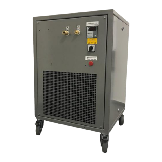
- Page 1 Industrial X-Ray Chiller Manual XRCA-3023-WA 3000 Watt Water to Air Chiller...
- Page 2 COMET AG Herrengasse 10 3175 Flamatt Switzerland Phone: +41 31 744 9000 Fax: +41 31 744 9090 E-Mail: info@comet.ch Internet: www.comet-xray.com Protection Notice Dissemination as well as copying of this document, utilization or posting of its contents is not permitted unless formally granted.
-
Page 3: Table Of Contents
Table of contents Inhalt 1. ABOUT THIS MANUAL ................6 1.1. Explanation of symbols and signs ............6 1.1.1. Safety symbols ............................6 1.1.2. Warning instructions ..........................6 1.1.3. Text designations ........................... 8 1.2. Illustrations ....................8 1.3. Terms of warranty ..................8 1.4. - Page 4 Table of contents 4.4. Unit components ..................19 4.4.1. Refrigeration circuit (primary circuit) ..................... 19 4.4.2. Cooling circuit (secondary circuit) ......................19 4.4.3. Temperature controller with display ..................... 19 4.5. Technical specifications ................20 5. TRANSPORT, PACKING AND STORAGE ..........21 5.1.
- Page 5 11.3. Final decommissioning, disposal ............48 11.4. Disposal of operating materials ............... 48 11.5. Disposal of refrigerant ................48 11.6. Return of the unit to COMET ..............48 12. WEAR PARTS AND SPARE PARTS ............. 49 13. ADDENDUM ................... 50 13.1.
-
Page 6: About This Manual
About this manual 1. About this manual This document is the manual for the cooling unit XRCA-3023 WA. It is based on international safety regulations. In your country other regulations may apply. This operating manual addresses the needs of the user of the unit. Its intention is to allow the safe operation of the unit. - Page 7 About this manual DANGER Reference to immediate danger to human health. DANGER Failure to comply with this warning instruction will result in severe irreparable injury and even death. WARNING Reference to recognizable hazard to human health. WARNING Failure to comply with this warning instruction may result in severe irreparable injury and even death.
-
Page 8: Text Designations
1.3. Terms of warranty General sale and delivery terms of COMET apply. The buyer accepts these terms, at the latest when signing the contract of purchase. The particular terms of warranty and duration of warranty of the unit in question can be taken from the contract documents as well as from the order confirmation. -
Page 9: Contact Information
Your name and address Name of contact at your address Product data as on identification plate: Type of unit, serial number, article number and year of manufacture Company contact: Mail: COMET AG Herrengasse 10 CH-3175 Flamatt Internet: http://www.comet-xray.com E-Mail: info@comet.ch... -
Page 10: Safety
Safety 2. Safety This chapter provides an overview of all important safety aspects for optimal protection of person- nel as well as safe and trouble-free operation. Disregarding this operating manual and warning instructions specified therein may result in consid- erable danger. 2.1. -
Page 11: Inadmissible Operating Conditions
NOTE The manufacturer is not liable for damage occurring when using the unit in a way it was not intended. When using the unit in a way it was not intended for, the manufacturer’s warranty given by COMET will expire. -
Page 12: Responsibilities Of The Unit Operator
Safety 2.2. Responsibilities of the unit operator 2.2.1. Planning and monitoring the safety measures It is a matter for the operator of the unit to plan the safety measures and to monitor their implemen- tation. The operator of the unit has to ensure that all persons involved with the unit have read and under- stood the operating instructions. -
Page 13: User Groups
Safety 2.3.2. User groups This operating manual distinguishes between the following user groups: Personal Qualifications Operating person- Adequate specific training in the following areas: The operation of the unit Operating sequences Specific experience in the following areas: Specific competencies and responsibilities, which are essential for the work on and with the unit ... -
Page 14: Exclusion Criteria
Safety 2.3.4. Exclusion criteria NOTE Operating personnel Operating personnel are only allowed to operate the unit. They are neither allowed to open the unit chassis, remove parts, connect or disconnect power or coolant fluids nor to do maintenance Persons allowed to operate and to maintain the unit must not be under the influence of intoxicating substances (e.g. -
Page 15: Guards
Safety Figure 1: Mounting position of the safety equipment of the unit (1) Pressure relief valve (3) Flow switch (4) Level guard (5) Temperature controller with display (7) Warning light „Coolant level low“ (6) On/Off switch for the refrigeration circuit 2.6. -
Page 16: In Case Of Accidents
Safety 2.8. In case of accidents Should you or another person be injured when working with the unit: Stay calm. Render first aid. Call the company first-aider without exception. If necessary, call your local emergency number. First Aid on accidents involving Tetrafluorethan The unit contains the refrigerant Tetrafluorethan (R134a) in a closed circuit system. -
Page 17: Product Identification
3.2. Identification plate The identification plate is attached to the housing of the unit and contains the following specifica- tions: Unit name, e.g. XRCA-3023-WA Name and address of the manufacturer Name and address of the distributor Article number ... -
Page 18: Unit Description
4. Unit description 4.1. Intended use The chiller unit XRCA-3023-WA is used for chilling a coolant circuit. The coolant circulates in a secondary circuit between the unit and the device to be cooled. The coolant itself is cooled down by an air ventilated refrigerated primary circuit. The maximum cooling capacity depends on the coolant outlet temperature and the ambient air temperature (see "Technical specifications"). -
Page 19: Unit Components
Unit description 4.4. Unit components The unit mainly consists of the following subassemblies. Additional unit information can be found in the diagrams contained in the addendum. Figure 3: Subassemblies (1) Refrigeration circuit (2) Cooling circuit (3) Casing (4) Temperature controller with display 4.4.1. -
Page 20: Technical Specifications
Unit description 1 LED 1 2 LED 2 3 LED 3 4 Control key UP 5 Control key DOWN 6 Control key SET 7 Temperature display in °C Changes to system settings are made through the control panel. During normal operation the dis- play will show the current temperature of the secondary cooling circuit. -
Page 21: Transport, Packing And Storage
Transport, packing and storage Coolant: Water or water-glycol mixture (ration 1:1) Coolant capacity: ca. 14 liters Performance data 3000 W at ∆T Cooling capacity: = 15 K temperature difference between the coolant outlet temperature and the ambient air temperature Throughput: >... -
Page 22: Checking The Delivery Condition
Transport, packing and storage WARNING Damage due to improper transportation! Injuries to persons and significant damage to property can occur in the case of im- proper transportation. When unloading the packed unit on delivery, as well as in-house transport, WARNING proceed very carefully and obey the symbols and instructions on the packag- ing. -
Page 23: Symbols On The Packaging
The packing material should only be removed just before the installation takes place. COMET advises to keep the transport pallet (if provided) for later transportation of the unit. Dispose packing material in accordance with environment protection requirements. -
Page 24: Handling With Industrial Truck
Transport, packing and storage 5.6. Handling with industrial truck WARNING Danger of injury due to tipping or falling loads! Bruises. Bone fracture. When Handling with industrial truck, observe the following basic rules: Wear the personal protective gear (e.g. protective footwear, protective gloves). ... -
Page 25: Storing The Unit
Protection caps for the coolant inlet and coolant outlet connections have only to be removed just before installation takes place. In order to store the units for more than 6 months, please consult COMET. 5.9. Preparing the unit for the further transport... - Page 26 Mount the unit cover, see "Removing and mounting the unit cover". Pack the unit according to the transport conditions that can be expected. COMET advises to use original packaging, if available, or an equivalent packaging. Mark the packaging with appropriate symbols; see "Symbols on the packaging".
-
Page 27: Installation And Commissioning
Installation and commissioning 6. Installation and commissioning 6.1. Requirements concerning the installation location 6.1.1. Installation location The location must be even. When choosing the installation location the following must be kept in mind: the flow of the cooling air must not be restricted, coolant inlet and coolant outlet connections must be easily accessible and all hoses must be installed without sharp bends. -
Page 28: Using The Unit For The First Time
Installation and commissioning 6.2. Using the unit for the first time NOTE Risk of damage to the unit due to temperature fluctuations! In case the unit is stored outside the operating temperature for a longer period of time, let the unit rest at the installation location so long, until it has reached ambient temperature. -
Page 29: Putting The Unit Into Operation
Installation and commissioning Connecting the unit electrically Requirements Coolant hoses connected, see "Connecting the coolant hoses". Coolant added, see "Adding coolant". Unit cover removed, see "Removing and mounting the unit cover". Procedure Connect the unit to mains by inserting the mains plug or making a mains connection as required by the particular periphery. -
Page 30: Controlling The Unit
Controlling the unit 7. Controlling the unit The unit is controlled by using the controls of the device that is to be cooled. All alarm and error signaling is only indicated on the control panel of the device that is to be cooled. To show the status of the unit multiple LEDs are available directly at the unit. -
Page 31: Pressure Relief Valve
The pressure relief valve is set by the manufacturer to a maximum pressure (factory setting: see "Technical specifications"). If any modification to this setting should be required, please contact the COMET service department to receive a briefing. NOTE The maximum pressure, which is reached by the device to be cooled, is affected by the length of the coolant hoses. - Page 32 Controlling the unit Figure 7: Temperature controller with display 1 Temperature display in °C 2 Control key SET 3 Control key UP / DOWN 7.3.3.1. Setting the coolant outlet temperature (T1) NOTE The hysteresis value of T1 is set as factory default to symmetrical 1°K. The value itself is stored in the internal parameter “P2”...
- Page 33 Controlling the unit 7.3.3.3. Setting the temperature guard (T3) NOTE The temperature T3 for the control of the „Temperature MAX“ warning light is stored in the internal parameter „P1“ of the temperature controller. A hysteresis represented by a symmetrical temperature value of ± 2,5 K around parameter “P1” has been set between flash-up of the alarm at exceeding of maximum temperature and ceasing of the alarm.
-
Page 34: Disruptions
Only sufficiently qualified personnel may perform maintenance on the unit. Do not attempt to repair the refrigeration circuit. If you cannot determine the error, please contact COMET services. 8.2. Disruption in operation The most common reason for disruption in operation of the unit is improper maintenance. Mainte- nance should be carried out regularly according to the maintenance intervals defined in chapter "Maintenance and cleaning", see "Maintenance and cleaning". - Page 35 Disruptions Main switch not turned on Turn main switch on. Operator Unit running but Coolant hoses buckled or Install the hoses with a larger radius Operator cooling capacity pitched in order to avoid sharp bends. is not available or too low Unit not placed properly Required clearance with the wall of Operator...
-
Page 36: Maintenance And Cleaning
Maintenance and cleaning 9. Maintenance and cleaning Diligent maintenance is the prime factor for assuring an error-free and efficient operation of the unit. All the maintenance tasks contained in this chapter have to be performed according to the maintenance intervals. 9.1. - Page 37 Maintenance and cleaning Improper maintenance WARNING Danger of injury due to improperly performed maintenance. Improper maintenance can lead to personal injury or material damage. Disconnect the unit from all sources of power during maintenance work. Ensure the sufficient working area at the beginning of the maintenance work. ...
-
Page 38: Maintenance Schedule
Maintenance and cleaning Environmental issues NOTE Danger to the environment due to improper handling! Environmentally conscious and anticipatory behavior of staff avoids environmentally hazardous im- pacts. The following principles apply for environmentally conscious behavior: Environmentally hazardous substances must not get into the soil or into the drains. They should be kept in appropriate containers. -
Page 39: Preparing The Unit For Maintenance
Maintenance and cleaning Inspect coolant hoses, con- Coolant hoses, pipes and Operating personnel nections and pipes for cracks connections are leaking and for leakages (visual in- spection) Inspect the coolant quality Turbidity, airborne particles Operating personnel (visual inspection) Every 3 months Clean or replace the filter Filter strainer damaged or Skilled employee strainer, see "Cleaning the... -
Page 40: Connecting The Coolant Hoses
Maintenance and cleaning – Absorbent cloth – Bonding agent – Protection caps Procedure Release coupling nipples from the coupling sockets. Secure the coolant inlet and coolant outlet connections with protection caps against soiling. The coolant hoses are now disconnected from the unit. 9.5. -
Page 41: Draining The Coolant
Maintenance and cleaning Connect an appropriate coolant hose to coolant inlet and coolant outlet respectively. Connect the coolant hoses to the corresponding connections of the unit to be cooled. The coolant hoses are now connected to the unit. 9.6. -
Page 42: Removing And Mounting The Unit Cover
Maintenance and cleaning Unit cover removed, see "Removing and mounting the unit cover". Tools and material required – Filling funnel – Measuring cup – Absorbent cloth Procedure Dismount the coolant filler plug. Add coolant up to 3 cm bellow the coolant filler opening. Coolant and quantity see "Technical specifications". -
Page 43: Cleaning The Filter Strainer
Maintenance and cleaning Mounting is the reverse order. Figure 11: Mounted unit cover (1) Cam locks 9.9. Cleaning the filter strainer WARNING Risk of burning and/or scalding due to possibly hot coolant. Coolant can reach high temperatures during operation and cause burns or scalding in the case of contact. -
Page 44: Cleaning The Heat Exchanger
Maintenance and cleaning Unscrew the cap of the filter strainer using the spanner (size 24). Remove the filter strainer and clean it. Check the filter strainer for damage. Damaged filter strainer has to be replaced immediately. If the filter strainer cannot be cleaned, replace the filter strainer. If the seal of the cap of the filter strainer is damaged, replace the filter strainer. -
Page 45: Cleaning The Casing
Maintenance and cleaning NOTE Damage to the fins of the heat exchanger due to improper handling of the unit. Damaged fins of the heat exchanger lead to a reduced cooling capacity. Take care not to damage the fins of the heat exchanger when cleaning the heat exchanger. ... -
Page 46: Repair
COMET services (see "Contact information"). In case of malfunctioning during the warranty period the unit must be sent to the COMET service department for repair (see "Contact information) or the COMET services website under http://www.comet-xray.com/Service/Contact-Form). -
Page 47: Decommissioning And Disposal
Decommissioning and disposal 11. Decommissioning and disposal 11.1. Temporary placing out of operation DANGER Electrical danger! Work on electrical installations may be carried out by trained and authorized electri- cians only. Switch off the unit before starting your work. DANGER ... -
Page 48: Final Decommissioning, Disposal
The unit was manufactured mainly from recyclable material. Make sure the components of the unit end up at a qualified company for disposal and recycling. Contact COMET for take back of end-of-life units (see "Contact information”) or the official COMET services website at http://www.comet-xray.com/Service/Contact-Form) or ask a company destined for disposal and recycling. -
Page 49: Wear Parts And Spare Parts
12. Wear parts and spare parts NOTE Spare parts must comply with the technical specifications defined by COMET. Original COMET parts are subject to strict obligations and fulfill these requirements. COMET does not provide warranty service in case of damages caused by the use of spare parts made by manufacturers other than COMET. -
Page 50: Addendum
Addendum 13. Addendum 13.1. Performance diagram Item/Position Designation ∆T [°C] Temperaturedifference Oil to water Cooling performance in watts Ambient temperature... -
Page 51: Flow Chart
Addendum 13.2. Flow chart... - Page 52 Addendum Flow chart diagram Item Designation Item Designation Coupling (water in) 1 / D Evaporator Flow controller Suction line accumulator Bypass valve Compressor D / 1 Evaporator Pressure controller LP/HP Temperature controller Check valve Level sensor Condenser Container Collector Filter Shut off-valve Pump Drier...
-
Page 53: Wiring Diagram
Addendum 13.3. Wiring diagram... - Page 54 Addendum Wiring diagram legend Item Designation Level sensor Flow controller Pressure switch HP/LP Protective relay for motor Pump Refrigerating unit Temperature controller N1T1 Forward temperature N2T2 Temperature max. N1T3 Antifreezing Relay refrigerating unit Disturbance level relay Relay RC element RC element Voltage change over switch Trafo Solenoid valve heat...
-
Page 55: Dimension Drawing
Addendum 13.4. Dimension drawing... - Page 56 Europe & RoW Asia COMET AG COMET Technologies USA, Inc. COMET China Herrengasse 10 100 Trap Falls Road Extension 1201 Gui Qiao Road CH-3175 Flamatt Shelton, CT 06484 Building 10, 1 floor Switzerland Pudong, Shanghai 201206 P.R.China T +41 31 744 90 00...
Need help?
Do you have a question about the XRCA-3023-WA and is the answer not in the manual?
Questions and answers