Advertisement
Table of Contents
- 1 Table of Contents
- 2 Introduction
- 3 General Safety Instructions
- 4 Getting Started
- 5 Weather Station Installation
- 6 Display Console Operation
- 7 Registration with Weather Server Websites
- 8 Wi-Fi Setup (Connect Your Device to the Console's Wi-Fi)
- 9 Upgrade Firmware
- 10 Other Console Features
- 11 Specifications
- 12 Maintenance
- 13 Troubleshooting Guide
- 14 Service
- 15 EC Declaration of Conformity
- 16 Disposal
- Download this manual
Advertisement
Table of Contents

Related Manuals for ACCUR8 DWS7100


Summary of Contents for ACCUR8 DWS7100
- Page 1 User Manual ACCUR8 DWS7100 Weather Station...
- Page 2 (www.metoffice.gov.uk). ACCUR8 products are tested for operation and functionality but have not been independently tested by a UKAS accredited laboratory. As part of our ongoing policy to improve the design and specification of our products, we reserve the right to change any detail given without prior notice.
-
Page 3: Table Of Contents
Contents Introduction ............................... 3 General Safety Instructions ........................3 Getting Started ............................5 Weather Station Installation ........................16 Display Console Operation ........................21 Registration with Weather Server Websites ...................28 Wi-Fi Setup (Connect your Device to the Console’s Wi-Fi) ..............39 Upgrade firmware ...........................45 Other Console Features .........................47 Specifications ............................50 Maintenance ............................52... -
Page 4: Introduction
® Thank you for purchasing the ACCUR8 DWS7100 Wi-Fi Weather Station with 7-in-1 Outdoor Sensor. The following user manual provides step-by-step instructions for installation, operation and troubleshooting. This user manual is to be considered a component of the device. Read carefully before using the device. - Page 5 • Never disassemble the device. In the event of a fault, please contact your retailer. • Do not expose this device to high temperatures and protect it from water and high humidity. • Do not immerse the unit in water. •...
-
Page 6: Getting Started
3. Getting Started The DWS7100 weather station consists of a display console (receiver), a sensor array with integrated outdoor transmitter, a thermo-hygrometer transmitter, and mounting hardware. 3.1 Parts List The DWS7100 weather station consists of the following parts (as referenced in Figure 1 below). - Page 7 Item Image Mounting bracket back plate (pole mount) Dimensions: 76 x 102 x 38mm Mounting pole Dimensions: 76 x 76 x 25mm Pole mounting nuts (M3) / bolts Ø3) Pole mounting nuts (M5) / bolts (Ø5) Tapping screws User manual...
- Page 8 Item Image UK power adaptor Figure 1 3.2 Recommended Tools ● Phillips screwdriver ● Compass or GPS (for wind direction calibration) ● Adjustable spanner ● Hammer and nail for hanging remote thermo-hygrometer transmitter. 3.3 Sensor Assembly Set Up Figure 2 shows the sensors included in the Integrated Outdoor Transmitter. Figure 2 Insert batteries into the transmitter.
- Page 9 Figure 3 Remove the battery door by removing the set screw, as shown in Figure 4. Figure 4 Insert 3 x AA batteries in the battery compartment, as show in Figure 5.
- Page 10 Figure 5 Close the battery door. Make sure the gasket (around the battery compartment) is properly seated prior to closing the door. Tighten the set screw. Note: Do not install the batteries backwards. You can permanently damage the sensors. The solar panel does not charge the batteries, so rechargeable batteries are not needed or recommended.
- Page 11 Figure 6 Setting up the thermo-hygrometer transmitter. Remove the battery door on the back of the sensor by removing the set screw, as shown in Figure 7. Figure 7 1. BEFORE inserting the batteries, locate the dip switches inside the battery compartment of the transmitter.
- Page 12 Figure 8 2. Channel Number: The DWS7100 supports up to eight transmitters. To set each channel number (the default is Channel 1), change Dip Switches 1, 2 and 3, as referenced in Table 1. 3. Temperature Units of Measure: To change the transmitter display units of measure (°F vs. °C), change Dip Switch 4, as referenced in Table 1.
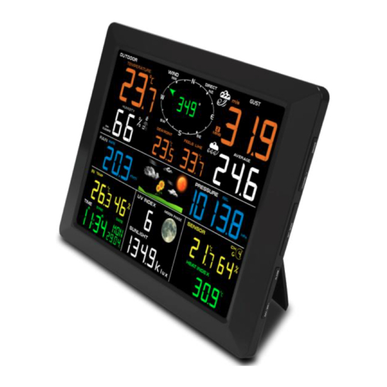
- Page 13 Figure 9 (1) temperature (2) temperature units (°F vs. °C) (3) channel number (4) relative humidity 7. Close the battery door. Make sure the gasket (around the battery compartment) is properly seated prior to closing the door. Tighten the set screw. 3.4 Display Console Display Console Layout The display console layout is shown in Figure 10.
- Page 14 Figure 10 1. Outdoor temperature display 19. Outdoor temperature and humidity display 2. Wi-Fi network 20. Scroll mode indicator 3. Outdoor humidity display 21. Channel 1-8 indicator 4. Outdoor humidity HI/LO alarm icon 22. Pressure (relative and absolute) display 5. Min/Max reset for 24h icon 23.
- Page 15 Display Console Set Up It is recommended to plug in the power supply to reduce the battery consumption and extend the service life. Note: The sensor array must be powered and updating before powering up the console, or the console will time-out searching for the sensors. Power up the console last. Make certain the weather station sensor array is at least 3m away from the console and within 30m of the console.
- Page 16 Note: The power adaptor is intended to be correctly oriented in a vertical or floor mounted position. The prongs are not designed to hold the plug in place if it is plugged into a ceiling, under-table or cabinet outlet. Figure 12 Note: If the power adaptor is plugged in, BL ON will display in the time area for three seconds when powered up.
-
Page 17: Weather Station Installation
4. Weather Station Installation 4.1 Pre-Installation Before installing your weather station in its permanent location, we recommend operating the weather station for one week in a temporary location with easy access. This will allow you to check out all of the functions, ensure proper operation, and familiarise you with the weather station and calibration procedures. - Page 18 Metal 90-100% 4.4 Installation of Integrated Outdoor Transmitter The DWS7100 can be used in both the Northern and Southern Hemispheres. Prior to installation, you will need to calibrate the wind direction as shown below. Northern Hemispheres (NOR) The cardinal directions (N, S, E, W) moulded on the body of the outdoor sensor are indicators for the Northern Hemisphere only.
- Page 19 Northern Hemispheres Southern Hemispheres Figure 13 Southern Hemispheres (SOU) For Southern Hemisphere installations, ignore these (N, S, E, W) and face the solar panel to the North (and in a sunny position) when it comes to installing the Integrated outdoor transmitter. Step 1: Install the Integrated outdoor transmitter and face the solar panel North.
- Page 20 Fasten the integrated transmitter to mounting pole brackets, with two ¢3 bolts and M3 nuts, as shown in Figure 14. Figure 14...
- Page 21 Attach the included mounting pole to your existing mounting pole with the four¢5 bolts and M5 nuts assembly, or fix on the wall with four tapping screws, as shown in Figure 15. Figure 15...
-
Page 22: Display Console Operation
4.5 Remote Thermo-hygrometer Transmitter installation It is recommended you mount the Thermo-hygrometer sensor outside in a shaded area. A north-facing wall is preferred because it is in the shade most of the day. Direct sunlight and radiant heat sources will result in inaccurate temperature readings. - Page 23 • Once for time, time/week and date • Twice for indoor temperature, dew point • Three for rainfall • Four for outdoor dew point temperature • Five for wind average • Six for pressure • Seven for sensor dew point 1.
- Page 24 8. Change Year. Press the SET(MODE) button again to set the calendar year. Press the [+] button or [-] button to adjust the calendar year. 9. Max/Min Clearing (default: ON). Press the SET(MODE) button again to set the max/min clearing mode (CLR).
- Page 25 After selecting one of the above options, press the SET(MODE) button to resync, and the display will return to normal mode. Do not press any buttons until the synchronisation is complete. The remote search icon will display constantly for 3 minutes until the signal is reacquired. 5.5 Reset Min/Max record Note: If you have more than one thermo-hygrometer sensor, the minimum and maximum value of all channels will be cleared in the reset mode.
- Page 26 5.8 Alarm Mode The DWS7100 includes the following alarms: • Time (There are two alarms for time: Alarm 1 and Alarm 2) • Outdoor Temperature • Outdoor Humidity • Outdoor AT (Apparent Temperature) • Outdoor Dew Point • Outdoor Feels Like Temperature •...
- Page 27 Setting the Alarms Press ALARM button to enter the alarm mode. Press and hold the SET/MODE button for three seconds. The first alarm parameter will begin flashing (alarm hour). To save the alarm setting and proceed to the next alarm parameter, Press (do not hold) the SET/MODE button.
- Page 28 30. Sunlight high alarm 31. Sensor (CH1) Temperature high alarm 32. Sensor (CH1) Temperature low alarm 33. Sensor (CH1) Humidity high alarm 34. Sensor (CH1) Humidity low alarm 35. Sensor (CH1) Heat Index high alarm 36. Sensor (CH1) Heat Index low alarm 37.
-
Page 29: Registration With Weather Server Websites
6. Registration with Weather Server Websites Register with WeatherCloud.net Note: This is best done on a desktop computer or laptop. Visit https://weathercloud.net/ and enter a username, email address and password (This is your Login password for the website, not your email account password. So, no private information will be exposed). - Page 30 Figure 19 4) As shown below, go to your email inbox and log in to the web address in the email you will have received. Figure 20 5) As shown below, click “here” to enter the homepage of the Weathercloud website. Figure 21...
- Page 31 6) As shown below, enter the email address and password you just registered to enter the Weathercloud website. Figure 22 Add a weather station device (it may take a few minutes). Figure 23 1) After signing up you will be prompted to add a device/ Select “Create device” and enter your station’s information: Boxes with red * must be filled in.
- Page 32 Figure 24 Note: You can select any Model number and Link type in the above boxes. 2) As shown below, click Get coordinates to identify your location of on the map, then click Done to confirm. Figure 25 3) As shown below, click Create.
- Page 33 Figure 26 4) As shown below, after registering successfully, please record the Weathercloud ID and Key information for later use. Figure 27 6.2 Register with Wunderground.com (Weather Underground) Note: The Weather Underground website is subject to change. Visit: https://Wunderground.com, and select the ‘Join’ link in the upper right and corner and create a Free Account.
- Page 34 Figure 28 2) As shown below, enter a username, email address and a password (this is your Login password for the website, not your email password. So, no private information will be exposed). Click ‘Sign up for free’. Figure 29 3) As shown below, registration has been successfully completed.
- Page 35 Figure 30 4) As shown below, click Log in and enter the email address and password you just registered. Figure 31 5) As shown below, click ‘My Profile’. Then enter Member Settings.
- Page 36 Figure 32 6) As shown below, click ‘Update home location’. Figure 33 7) As shown below, you will then be prompted to add a device/ Select ‘Add New Device’ Figure 34 8) As shown below, click ‘Personal Weather Station’.
- Page 37 Figure 35 9) As shown below, select Address by inputting an address or select Manual to position your address automatically. Then click Next:...
- Page 38 Figure 36 10) As shown below, you will then be prompted to add more information about your device. Complete the appropriate information then click ‘I Accept’ and ‘Next’: Boxes with red (Required) must be filled in. Note: You can select any Wi-Fi weather station model in the Device Hardware box; we recommend ‘AcuRite 5-in-1 Weather Station with Wi-Fi’.
- Page 39 Figure 37 11) As shown below, after registering the host successfully, please record Station ID and Station Key information for use later. These details will be needed when you configure your console for Wi-Fi access. Figure 38 12) As shown below, registration is done successfully. Figure 39...
-
Page 40: Wi-Fi Setup (Connect Your Device To The Console's Wi-Fi)
7. Wi-Fi Setup (Connect your Device to the Console’s Wi-Fi) Note: If you own a dual band router (2.4 GHz and 5.0 GHz), make sure you connect to the 2.4 GHz band, otherwise it will fail to connect the weather station to Wi-Fi. You may need to check your router documentation regarding how to do this. - Page 41 Figure 40 Example 2. Connect to the console Wi-Fi server with a Mac. Choose the Settings icon Network. Connect to the WeatherHome------ Wi-Fi network, as shown in Figure 41 (your Wi-Fi network name may be slightly different, but will always begin with WeatherHome------ Figure 41 Example 3.
- Page 42 Figure 42 Example 4. Connect to the console Wi-Fi server with an Android device. From the Apps icon, choose the Settings icon and Wi-Fi. Connect to the WeatherHome------ Wi-Fi network, as shown in Figure 43 (your Wi-Fi network name may be slightly different, but will always begin with WeatherHome------).
- Page 43 Once connected, enter the following IP address into any web browser: http://192.168.5.1 to access the console’s web interface. Note: Some browsers will treat 192.168.5.1 as a search, so make sure you include the header http://, i.e.: http://192.168.5.1, not 192.168.5.1 Enter the following information into the web interface (Figure 44). Make sure all of the information is entered prior to selecting Save.
- Page 44 The following table provides times zones throughout the world. Locations in the eastern hemisphere are positive, and locations in the western hemisphere are negative. Hours from Time Zone Cities IDLW: International Date Line West NT: Nome Nome, AK AHST: Alaska-Hawaii Standard Honolulu, HI CAT: Central Alaska HST: Hawaii Standard...
- Page 45 Hours from Time Zone Cities JST: Japan Standard Tokyo GST: Guam Standard Sydney Magadan IDLE: International Date Line East Wellington, New Zealand NZST: New Zealand Standard If all of the information you entered is correct, press save to confirm (Figure 45). If it does not, check your web interface information again.
-
Page 46: Upgrade Firmware
NOTE: When the console successfully connects to any weather server websites, the data signal icon will appear on the LCD display (In front of the Indoor Temperature). If the data signal icon is flashing, the console is currently uploading to the server. If the icon disappears, the console has not connected to the weather server for more than 30 minutes. - Page 47 Use your smart phone, tablet, or computer to connect to the console through Wi-Fi (see: Examples 1-4 in the Wi-Fi Setup section). Once connected, enter the following IP address into the browser’s address bar: http://192.168.5.1/upgrade.html Figure 48 Once connection is successful, it will jump to the ‘Upload Setting’ screen automatically. Figure 49 Press Select File button to select the upgraded firmware as shown in figure 50 below.
-
Page 48: Other Console Features
Figure 51 NOTE: In this upgrade only Wi-Fi firmware is updated. The console does not reset. Once the upgrade is completed, the console will automatically exit WAP mode. 9. Other Console Features The following section describes additional features and display icons. Weather Forecasting Note: The weather forecast or pressure tendency is based on the rate of change of barometric pressure. - Page 49 Partly Cloudy Pressure is falling and the previous condition is sunny or Pressure is rising and the previous condition is cloudy. Cloudy Pressure is falling and the previous condition is partly cloudy or Pressure is rising and the previous condition is rainy. Rainy Pressure is falling and the previous condition is cloudy.
- Page 50 Figure 52 At temperatures greater than 26.7°C (80°F), the heat index is displayed, as shown in the National Weather Service Heat Index Table below: When the temperature is between 4.4°C (40°F) and 26.7°C (80°F), the OUT temperature is displayed (‘Feels Like’...
-
Page 51: Specifications
The concept of apparent temperature (AT) is a linear regression that is not restricted and is more appropriate to outside conditions because it includes wind. and is intended as an assessment of what exposed body surfaces feel like in cold, windy conditions. Regression equations of this universal scale are formulated for ‘indoors’/’outdoors in shade but exposed to wind’/’outdoors exposed to wind and solar radiation’. - Page 52 Sensors 1-8 Humidity 10 to 99% ± 5% (only guaranteed between 20 to 90%) UV Index 1 to 15+ ± 1 ± 1 Sunlight 0 to 200klux ± 15% ± 15% Rain 0 to 9999mm <15mm: ±1 mm, <1000mm (0.3mm) 15mm to 9999mm: ±7% >1000mm (1mm) Wind Direction...
-
Page 53: Maintenance
11. Maintenance Clean the rain gauge of the Integrated Outdoor Transmitter once every 3 months. • Unscrew the rain collector funnel by turning it 30° counter-clockwise. • Gently remove the rain collector funnel. • Clean and remove any debris or insects. •... -
Page 54: Troubleshooting Guide
12. Troubleshooting Guide Problem Solution Wireless sensor not reporting into If the signal from any sensor is lost, dashes (--.-) will be console. displayed on the screen. To reacquire the signal, press and hold the CHANNEL/+ button for 3 seconds, choose the lost sensor and the remote search icon There are dashes (--.-) on the display will be constantly displayed. - Page 55 Problem Solution Use the calibration feature to match the indoor and outdoor temperature to a known source. Indoor and Outdoor Humidity do not Allow up to one hour for the sensors to stabilise due to agree signal filtering. The indoor and outdoor humidity sensors should agree within 10 % (the sensor accuracy is ±...
- Page 56 Problem Solution Confirm your password or key is correct. It is Data not reporting to the password you registered on www.wunderground.com Wunderground.com. Your Wunderground.com password cannot begin with a non- www.weathercloud.net alphanumeric character (a limitation of Wundeground.com, not the station). Example, $worknet is not a valid password, but worknet$ is valid.
-
Page 57: Service
Phone: 01243 558 280 14. EC Declaration of Conformity Tempcon Instrumentation Limited declares that the equipment type with item number DWS7100 complies with EMC Directive 204/108/EC. The full text of the declaration of conformity is available on request from the address above.
Need help?
Do you have a question about the DWS7100 and is the answer not in the manual?
Questions and answers