
Related Manuals for Acer Aspire Z5760


Summary of Contents for Acer Aspire Z5760
- Page 1 Aspire Z3760 / Z3761 / Z5760 / Z5761 All-In-One Computer Service Guide Service guide files and updates are available on the Acer/CSD web site; for more information, go to http://csd.acer.com.tw PRINTED IN TAIWAN...
-
Page 2: Revision History
Revision History Refer to the table below for changes made on this version of the Aspire Z3760 / Z3761 / Z5760 / Z5761 All-In-One Computer Service Guide. Date Chapter Updates Aspire Z3760 / Z3761 / Z5760 / Z5761 AIO Computer Service Guide... - Page 3 Copyright Copyright © 2010 by Acer Incorporated. All rights reserved. No part of this publication may be reproduced, transmitted, transcribed, stored in a retrieval system, or translated into any language or computer language, in any form or by any means, electronic, mechanical, magnetic, optical, chemical, manual or otherwise, without the prior written permission of Acer Incorporated.
- Page 4 Conventions The following textual conventions are used in this service guide. Denotes actual messages that appear on screen. SCREEN MESSAGES NOTE Gives additional information related to the current topic. WARNING Alerts you to any physical risk or system damage that might result from doing or not doing specific actions.
-
Page 5: Fru Information
FRU list of this printed service guide. You MUST use the list provided by your regional Acer office to order FRU parts for repair and service of customer machines. Aspire Z3760 / Z3761 / Z5760 / Z5761 AIO Computer Service Guide... - Page 6 Aspire Z3760 / Z3761 / Z5760 / Z5761 AIO Computer Service Guide...
-
Page 7: Table Of Contents
Table of Contents Chapter 1 – Features and Specifications 1 System Features 1 Physical Specifications 2 System Tour 3 Front View 3 Left View 4 Right and Rear Views 5 Hardware Specifications 6 Processor 6 Chipsets 6 BIOS 6 Memory 6 Hard Disk Drive 7 Optical Disc Drive 7 Ethernet 8... - Page 8 Removing the Heat Sink Fan (HSF) Assembly 51 Removing the Processor 52 Removing the Memory Modules 53 Removing the Power Supply Unit 54 Removing the Mainboard 56 Removing the I/O Shield 57 Removing the System Fan Brace 58 Removing the Side Bezel 59 Removing the Front Bezel 60 Removing the Capacitive LED Board 62 Removing the Bluetooth Module 63...
-
Page 9: Chapter 1 - Features And Specifications
• One PCI Express 2.0 x1 slot (for TV tuner card installation) • Display size – Aspire Z3760 / Z3761: 21.5-inch LCD panel – Aspire Z5760 / Z5761: 23-inch LCD panel • Windows 7 compliant multi-touchscreen function for Aspire Z3761 / Z5761 •... -
Page 10: Physical Specifications
Component Card reader Connectivity DIgital TV tuner (optional) Digital media protection Ventilation Power supply Operating system support Antivirus software Security Power management Sustainability compliance Physical Specifications Aspect System dimension (W × H × D) Mainboard form factor Mainboard dimensions (W × H) Description •... -
Page 11: System Tour
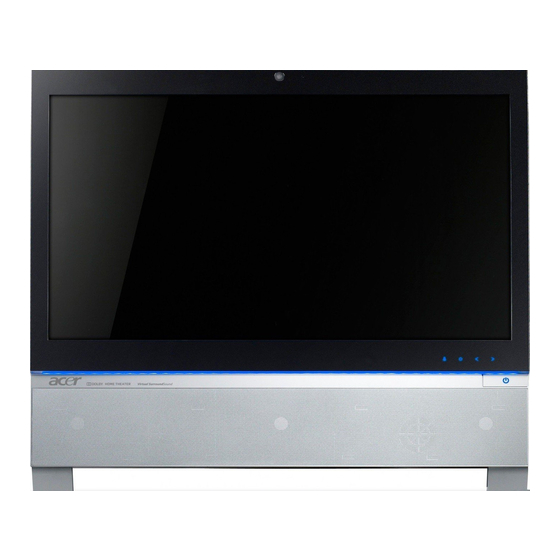
System Tour The pictures and tables in this section illustrate the physical outlook of the computer. Front View Item NOTES: • Icons for the capacitive keys are only visible when the system is turned on. • The auxiliary lighting capacitive key is designed to provide a light source when using a keyboard in low-light conditions. -
Page 12: Left View
Left View Item Icon Component B-CAS card (optional) cover Optical disc drive (ODD) I/O cable cover 9-in-1 card reader HD dual digital TV tuner (optional) Line-in jack Line-out jack Microphone jack Item Icon Aspire Z3760 / Z3761 / Z5760 / Z5761 AIO Computer Service Guide Component USB ports Ethernet port (RJ-45) -
Page 13: Right And Rear Views
Right and Rear Views Item Note: Item # 1 is compliant with the 100 × 100 mm VESA standard. Aspire Z3760 / Z3761 / Z5760 / Z5761 AIO Computer Service Guide Icon Component Mounting holes for wall mount option USB ports Microphone jack Headphone jack Kensington slot... -
Page 14: Hardware Specifications
Hardware Specifications Processor • Socket: LGA1155 • Package type: 32 nm Item Specification Series Intel Core Second Generation Processor Family Model i3-2100 i5-2300 CPU speed 3.1 GHz 2.8 GHz Bus speed 1333 MHz 1333 MHz No. of cores L3 cache size 3 MB 6 MB 65 W... -
Page 15: Hard Disk Drive
Hard Disk Drive Item Specification Controller Integrated in the Intel H67 chipset Form factor 3.5-inch 9.5 mm Interface SATA, Second or Third Generation Supported capacities 320 GB • HGST HDS721032CLA362 (7200 rpm) • Seagate ST3320418AS (7200 rpm) • WD WD3200AAJS-22L7A0 (7200 rpm) 500 GB •... -
Page 16: Ethernet
Ethernet Item Specification Controller Intel 82579V Gigabit Ethernet Controller LAN protocol 10/100/1000 Mbps LAN connector type RJ-45 Wireless LAN Item Specification Model Realtek RTL8191SU Standards supported • IEEE 802.11b/g/n compatible WLAN • IEEE 802.11e QoS Enhancement (WMM) • IEEE 802.11h TPC, Spectrum Measurement •... -
Page 17: Display
5.0 V 0 to 50 °C (90% RH, 240h) -20 to 60 °C (90% RH; 48h) • Aspire Z3760: No • Aspire Z3761: Yes Specification Aspire Z5760 / Z5761 LGD LM230WF5-TLC1 23-inch 509.184 × 268.416 mm White LED LVDS 2-port 1920 ×... - Page 18 Aspire Z3760 / Z3761 / Z5760 / Z5761 AIO Computer Service Guide...
-
Page 19: Chapter 2 - System Utilities
System Utilities CMOS Setup Utility CMOS Setup Utility is a hardware configuration program built into the system ROM. Since most systems are already properly configured and optimized, there is normally no need to run this utility. You will need to run this utility under the following conditions: •... -
Page 20: Accessing The Setup Utility
Accessing the Setup Utility Turn on the computer. If the computer is already turned on, save your data and close all open applications, then restart the computer. During POST, press Delete. If you fail to press Delete before POST is completed, you will need to restart the computer. Use the Left/Right arrow keys to move between the menu screens, then press Enter to view that menu tab. -
Page 21: Navigating Through The Setup Utility
Navigating through the Setup Utility Use the keys listed in the legend bar on the bottom of the Setup screen to work your way through the various menu and submenu screens of the Setup Utility. The table below lists these legend keys and their respective functions. -
Page 22: Main Menu
Main menu Field Description System BIOS Version Current system BIOS version Build Date Date when the system BIOS was built. Processor <model> Processor model installed Core Frequency Core frequency of the installed processor Count Multi-core factor of the installed processor (number of processor cores) Memory Size Size of system memory detected during boot-up... -
Page 23: Advanced Menu
Advanced menu Field Miscellaneous Advanced Chipset Configuration Integrated Peripherals PC Health Status Aspire Z3760 / Z3761 / Z5760 / Z5761 AIO Computer Service Guide Description Access this submenu to view the properties of installed SATA devices and configure miscellaneous system settings. Access this submenu to enable or disable various Intel technology functions and configure video memory settings. -
Page 24: Miscellaneous Submenu
Miscellaneous submenu Field Description AHCI Port 1-4 Your computer supports four SATA channels, each channel allows one SATA device to be installed. Press Enter to display the individual configuration screen of installed SATA drive(s). Clock to All DIMM/ When enabled, clock signals will be sent to the PCI and memory slots PCI/PCIE regardless of whether the slot is occupied or not. -
Page 25: Advanced Chipset Configuration Submenu
Advanced Chipset Configuration submenu Field Description Intel EIST Select whether to enable the Enhanced Intel SpeedStep Technology. EIST allows a compliant OS to dynamically adjust the processor voltage and core frequency based on system usage. This can result in decreased average power consumption and decreased average heat production. -
Page 26: Integrated Peripherals Submenu
Integrated Peripherals submenu Field Description Onboard SATA Controller Enables or disables the onboard SATA controller. Onboard SATA Mode Set the operating mode for the onboard SATA controller. Onboard USB Controller Enables or disables the onboard USB controller. Legacy USB Support Enables or disables support for a USB mouse and USB keyboard. - Page 27 PC Health Status submenu Field CPU Temperature (PECI Mode) System Temperature PCH Temperature CPU Fan Speed System Fan Speed CPU Core +1.05V +3.30V +5.00V +12.0V 5VSB VBAT Smart Fan Aspire Z3760 / Z3761 / Z5760 / Z5761 AIO Computer Service Guide Description These items lets you monitor the parameters for critical voltages, temperatures and fan speeds.
-
Page 28: Power Menu
Power menu Field Description ACPI Suspend Mode Use this item to define how your system suspends. Default value is S3 (STR), the suspend mode is suspend to RAM, i.e., the system shuts down with the exception of a refresh current to the system memory. -
Page 29: Security Menu
Security menu Field Description Supervisor Password Displays the supervisor password status. When set to Installed, this password will allow the user to access and change all settings in the Setup Utility. User Password Displays the user password status. Only the following menus will be accessible when this password is used to logged in: •... - Page 30 To set a system password: NOTE You need to set a supervisor password first before setting the user password. Select Change Supervisor Password or Change User Password, then press Enter. The password box appears. Type a password then press Enter. IMPORTANT Be very careful when typing your password because the characters do not appear on the screen.
-
Page 31: Boot Options Menu
Boot Options menu Field Description Set Boot Priority Displays the device assigned to the specified boot sequence. The Setup Utility attempts to boot the operating system in this order. By default, the computer searches 1st Boot Device for boot devices in the following order: 2nd Boot Device •... -
Page 32: Exit Menu
Exit menu Field Description Save and Exit Setup Save changes made and close the Setup utility. Keyboard shortcut: F10 Discard Changes and Discard changes made and close the Setup utility. Exit Setup Save Changes Save all changes made to the Setup utility. Discard Changes Discard all changes made to the Setup utility and load the previous configuration settings. -
Page 33: Chapter 3 - System Disassembly
System Disassembly This chapter provides step-by-step instructions on how to disassemble the computer for maintenance and troubleshooting purposes. Disassembly Tools In performing the disassembly process, you will need the following tools: • Wrist-grounding strap and conductive mat for preventing electrostatic discharge •... -
Page 34: Disassembly Procedures
Disassembly Procedures Removing the Computer Stand Perform the “Pre-disassembly Procedure” on page 25. Use a flat screwdriver to pry off the plastic shell covering the computer stand screws. Remove the screws securing the computer stand. Quantity Color Torque Black 8.0 ± 0.3 kgf-cm Aspire Z3760 / Z3761 / Z5760 / Z5761 AIO Computer Service Guide Part Number –... -
Page 35: Removing The I/O Cable Cover
Remove the computer stand. Removing the I/O Cable Cover Perform the “Pre-disassembly Procedure” on page 25. Remove the I/O cable cover. Aspire Z3760 / Z3761 / Z5760 / Z5761 AIO Computer Service Guide... -
Page 36: Removing The Rear Cover
Removing the Rear Cover Remove the computer stand and the I/O cable cover by following the procedures described on pages 26 and 27. Grasp the rear cover on the I/O port area and pull up to disengage the cover from the front bezel. The picture below shows the location of the plastic snaps securing the rear cover. -
Page 37: Removing The I/O Cable Plate
Removing the I/O Cable Plate Remove the rear cover by following the procedure described on the previous page. Push the latch to disengage the I/O cable plate from the chassis (a), then remove the I/O cable plate (b). Removing the Optical Disc Drive Remove the rear cover by following the procedure described on page 28. - Page 38 Remove the screw securing the ODD. Quantity Slide the ODD outward, then disconnect the ODD SATA cable from the drive. Remove the ODD from the chassis. Color Torque Black 4.5 ± 0.3 kgf-cm Aspire Z3760 / Z3761 / Z5760 / Z5761 AIO Computer Service Guide Part Number 86.00B75.240...
-
Page 39: Removing The Wlan Module
Remove the screw securing the ODD bracket. Quantity Detach the ODD bezel from the module. Removing the WLAN Module Remove the rear cover by following the procedure described on page 28. Remove the screws securing the scaler board cover. Quantity Aspire Z3760 / Z3761 / Z5760 / Z5761 AIO Computer Service Guide Color Torque... - Page 40 Remove the scaler board cover. Disconnect the WLAN antennas. Remove the screw securing the WLAN module. Quantity Color Torque Chrome 4.5 ± 0.3 kgf-cm Aspire Z3760 / Z3761 / Z5760 / Z5761 AIO Computer Service Guide Part Number 86.7A122.4R0...
-
Page 41: Removing The Scaler Board
Remove the WLAN module. Removing the Scaler Board Remove the rear cover by following the procedure described on page 28. Remove the screws securing the scaler board cover. Quantity Remove the scaler board cover. Aspire Z3760 / Z3761 / Z5760 / Z5761 AIO Computer Service Guide Color Torque Chrome... - Page 42 Disconnect all the cables from the scaler board. Remove the screws securing the scaler board. Quantity Color Torque Chrome 6.0 ± 0.5 kgf-cm Aspire Z3760 / Z3761 / Z5760 / Z5761 AIO Computer Service Guide Part Number 86.00B75.240...
-
Page 43: Removing The Usb/Audio Board
Remove the scaler board. A circuit board that is >10 cm above image. Follow local regulations for disposing this type of circuit board. Removing the USB/Audio Board Remove the rear cover by following the procedure described on page 28. Remove the screw securing the USB/audio board cover. Quantity Aspire Z3760 / Z3761 / Z5760 / Z5761 AIO Computer Service Guide has been highlighted with a yellow rectangle as shown in the... - Page 44 Slide the USB/audio board cover outward to disengage the cover tabs from the chassis, then remove the USB/audio board cover. Disconnect the two cables from the USB/audio board. Remove the screws securing the USB/audio board. Quantity Color Torque Chrome 6.0 ± 0.5 kgf-cm Aspire Z3760 / Z3761 / Z5760 / Z5761 AIO Computer Service Guide Part Number 86.00B75.240...
-
Page 45: Removing The Speakers
Slide the USB/audio board out of its tabs. A circuit board that is >10 cm above image. Follow local regulations for disposing this type of circuit board. Removing the Speakers Remove the rear cover by following the procedure described on page 28. Remove the scaler board by following the procedure described on page 33. - Page 46 Remove the screws securing the speakers. Quantity Remove the speakers. Color Torque Chrome 4.5 ± 0.5 kgf-cm Aspire Z3760 / Z3761 / Z5760 / Z5761 AIO Computer Service Guide Part Number 86.00B75.240...
-
Page 47: Removing The Side Board Cover
Removing the Side Board Cover Remove the rear cover by following the procedure described on page 28. Remove the screw securing the side board cover. Quantity Remove the side board cover. Aspire Z3760 / Z3761 / Z5760 / Z5761 AIO Computer Service Guide Color Torque Chrome... -
Page 48: Removing The Converter Board
Removing the Converter Board Remove the side board cover by following the procedure described on the previous section. Disconnect all cables from the converter board. Remove the screws securing the converter board. Quantity Color Torque Chrome 6.0 ± 0.5 kgf-cm Aspire Z3760 / Z3761 / Z5760 / Z5761 AIO Computer Service Guide Part Number 86.00B75.240... -
Page 49: Removing The Touchscreen Control Board
Remove the converter board. A circuit board that is >10 cm above image. Follow local regulations for disposing this type of circuit board. Removing the Touchscreen Control Board The touchscreen feature only applies to the Aspire Z3761 and Z5761 models. IMPORTANT If the LCD touchscreen panel becomes defective, the LCD panel with the touchscreen film and the touchscreen control board should be replace. - Page 50 Remove the screws securing the touchscreen control board. Quantity Remove the touchscreen control board. Color Torque Chrome 4.5 ± 0.3 kgf-cm Aspire Z3760 / Z3761 / Z5760 / Z5761 AIO Computer Service Guide Part Number 86.00B75.240...
-
Page 51: Removing The Wall Mount Plate
Removing the Wall Mount Plate Remove the rear cover by following the procedure described on page 28. Remove the screws securing the wall mount plate. Quantity Remove the wall mount plate. Aspire Z3760 / Z3761 / Z5760 / Z5761 AIO Computer Service Guide Color Torque Chrome... -
Page 52: Removing The Graphics Card
Removing the Graphics Card Remove the wall mount plate by following the procedure described on the previous section. Remove the two hex screws securing the DVI cable to the I/O port panel (a), then detach the cable from the panel (b). Quantity Remove the two hex screws securing the DVI cable to the graphics card (a), then detach the cable from the card (b). - Page 53 Remove the graphics card assembly from the mainboard. Remove the screw securing the graphics card bracket. Quantity Disconnect the graphics card from the riser board. A circuit board that is >10 cm above image. Follow local regulations for disposing this type of circuit board. Aspire Z3760 / Z3761 / Z5760 / Z5761 AIO Computer Service Guide Color Torque...
-
Page 54: Removing The System Fan
Remove the screws securing the graphics card riser board, then remove the riser board from the bracket. Quantity A circuit board that is >10 cm above image. Follow local regulations for disposing this type of circuit board. Removing the System Fan Remove the wall mount plate by following the procedure described on page 43. - Page 55 Disconnect the system fan cable from the mainboard. Remove the screws securing the system fan. Quantity Remove the system fan from the chassis. Aspire Z3760 / Z3761 / Z5760 / Z5761 AIO Computer Service Guide Color Torque Black 5.0 ± 0.5 kgf-cm Part Number 86.TAR28.8R0...
-
Page 56: Removing The Hard Disk Drive
Removing the Hard Disk Drive Remove the wall mount plate by following the procedure described on page 43. Remove the graphics card assembly by following the procedure described on page 44. Disconnect the power and SATA cables from the hard drive. Remove the screw securing the hard drive. - Page 57 Remove the screws securing the hard drive bracket. Quantity Remove the hard drive from its bracket. Aspire Z3760 / Z3761 / Z5760 / Z5761 AIO Computer Service Guide Color Torque Chrome 6.0 ± 0.5 kgf-cm Part Number 86.5A5B6.012...
-
Page 58: Removing The Tv Tuner Card
Removing the TV Tuner Card Remove the wall mount plate by following the procedure described on page 43. Disconnect the TV tuner card cable. Disconnect TV tuner card from its expansion slot. A circuit board that is >10 cm above image. Follow local regulations for disposing this type of circuit board. has been highlighted with a yellow rectangle as shown in the Aspire Z3760 / Z3761 / Z5760 / Z5761 AIO Computer Service Guide... -
Page 59: Removing The Heat Sink Fan (Hsf) Assembly
Removing the Heat Sink Fan (HSF) Assembly Remove the wall mount plate by following the procedure described on page 43. Disconnect the HSF cable from its mainboard connector. Loosen the HSF's spring-loaded screws in a diagonally opposite pattern (an "X" pattern). Quantity Remove the HSF assembly. -
Page 60: Removing The Processor
Removing the Processor Remove the HSF assembly by following the procedure described on the previous section. Disengage the load lever from its latch (a), then rotate the load lever to the open position (b). Open the retention plate to expose the socket body. Aspire Z3760 / Z3761 / Z5760 / Z5761 AIO Computer Service Guide... -
Page 61: Removing The Memory Modules
Gently lift the processor out of its socket. IMPORTANT When installing a processor: • Note the golden arrow on the corner to make sure the processor is properly oriented over the socket. • Moisten a soft cloth with isopropyl alcohol and clean the processor die to remove any thermal grease residue. -
Page 62: Removing The Power Supply Unit
Removing the Power Supply Unit Remove the wall mount plate by following the procedure described on page 43. Disconnect the 4-pin and 24-pin ATX power cables from their mainboard connectors. Press the top portion of the cable’s retaining latch Pull the cable straight up from its connector. Disconnect the PSU extension cable. - Page 63 Slide the PSU to the left to disengage it from the chassis (a), then pull the ATX cables through the chassis opening (b). Remove the screw securing the PSU to it cage. Quantity Remove the PSU from its cage. Aspire Z3760 / Z3761 / Z5760 / Z5761 AIO Computer Service Guide Color Torque Chrome...
-
Page 64: Removing The Mainboard
Removing the Mainboard Remove the wall mount plate by following the procedure described on page 43. Remove the graphics card, system fan, hard drive, and the TV tuner card by following the procedures described on pages 44–50. Remove the HSF assembly, processor, and the memory modules by following the procedures described on pages 51–53. -
Page 65: Removing The I/O Shield
Remove the mainboard. • A circuit board that is >10 cm above image. Follow local regulations for disposing this type of circuit board. • The RTC battery has been highlighted with a yellow circle in the above image. Detach the RTC battery and follow local regulations for disposing it. -
Page 66: Removing The System Fan Brace
Removing the System Fan Brace Remove the wall mount plate by following the procedure described on page 43. Remove the graphics card assembly by following the procedure described on page 44. Remove the screws securing the system fan brace. Quantity Remove the system fan brace. -
Page 67: Removing The Side Bezel
Removing the Side Bezel Remove the rear cover by following the procedure described on page 28. Remove the screws securing the side bezel. Quantity 11 (1-11) 2 (12-13) Push the plastic tabs securing the side bezel outward. Remove the side bezel. Aspire Z3760 / Z3761 / Z5760 / Z5761 AIO Computer Service Guide Color Torque... -
Page 68: Removing The Front Bezel
Removing the Front Bezel Remove the rear cover by following the procedure described on page 28. Remove the side bezel by following the procedure described on page 59. Disconnect the webcam cable. Remove the screws securing the front bezel. Quantity 4 (1-4) 2 (5-6) Color... - Page 69 Turn over the unit with the display screen facing up. Push the plastic tabs securing the front bezel. Detach the front bezel from the chassis and turn it over the speaker mesh cover. The front bezel is still attached to the chassis by the cables connected to the capacitive LED board, Bluetooth module, and the light bars.
-
Page 70: Removing The Capacitive Led Board
Removing the Capacitive LED Board Remove the front bezel by following the procedure described on page 60. Remove the tape securing the capacitive LED board. Disconnect the capacitive LED board cable. Use a flat screwdriver to pry off the capacitive LED board from the front bezel. Aspire Z3760 / Z3761 / Z5760 / Z5761 AIO Computer Service Guide... -
Page 71: Removing The Bluetooth Module
Removing the Bluetooth Module Remove the front bezel by following the procedure described on page 60. Remove the tape protecting the Bluetooth module. Remove the Bluetooth module from the front bezel and turn it over to expose the cable connector underneath it. -
Page 72: Removing The Light Bars
Removing the Light Bars Remove the front bezel by following the procedure described on page 60. Pull up the tabs securing the two light bars. Remove the light bars from the front bezel. Disconnect the light bars’ cables. Aspire Z3760 / Z3761 / Z5760 / Z5761 AIO Computer Service Guide... -
Page 73: Removing The Webcam Module
Removing the Webcam Module Remove the front bezel by following the procedure described on page 60. Push the tabs securing the webcam module, then remove the module. Removing the Power Button Remove the front bezel by following the procedure described on page 60. Use a flat screwdriver to pry off the power button from the speaker mesh cover. -
Page 74: Removing The Speaker Mesh Cover Assembly
Removing the Speaker Mesh Cover Assembly Remove the front bezel by following the procedure described on page 60. Disengage the speaker mesh cover assembly from the chassis. Expose the bottom side of the cover to access the power button/LED cable. Remove the tape protecting the power button/LED cable. -
Page 75: Removing The Lcd Panel
Use a flat screwdriver to pry the speaker mesh cover from the bottom cover. Removing the LCD Panel Remove the front bezel by following the procedure described on page 60. Disconnect the LCD LVDS cable from the scaler board. Refer to step 4 on page 34. Disconnect the converter board 2-pin FFC. -
Page 76: Removing The Lcd Panel Brackets
Remove the LCD panel from the chassis. Removing the LCD Panel Brackets Remove the LCD panel by following the procedure described on the previous section. Detach the brackets from the LCD panel. Removing the LCD LVDS Cable Remove the LCD panel by following the procedure described on page .67. Press on both sides of the LCD LVDS cable (a), then pull the cable from the panel (b). -
Page 77: Removing The System Cables
Removing the System Cables Remove the LCD panel by following the procedure described on page 67. Remove the tapes securing the system cables (including the WLAN antennas on the top side of the chassis), then release the cables from the chassis. Aspire Z3760 / Z3761 / Z5760 / Z5761 AIO Computer Service Guide... - Page 78 Aspire Z3760 / Z3761 / Z5760 / Z5761 AIO Computer Service Guide...
-
Page 79: Chapter 4 - Troubleshooting
System Check Procedures IMPORTANT The diagnostic tests described in this chapter are only intended to test Acer products. Non-Acer products, prototype cards, or modified options can give false errors and invalid system responses. -
Page 80: System Internal Inspection
Verify that all cable connections inside the system are firmly and properly attached to their appropriate mainboard connectors. 10. Verify that all components are Acer-qualified and supported. 11. Reinstall the wall mount plate. 12. Reinstall the rear cover and the TV stand. -
Page 81: Boot Block Recovery Code Checkpoints
Checkpoint Description If memory sizing module not executed, start memory refresh and do memory sizing in bootblock code. Do additional chipset initialization. Re-enable CACHE. Verify that flat mode is enabled. Test base 512 KB memory. Adjust policies and cache first 8 MB. Set stack. Bootblock code is copied from ROM to lower system memory and control is given to it. -
Page 82: Post Code Checkpoints
Checkpoint Description The flash has been updated successfully. Make flash write disabled. Disable ATAPI hardware. Restore CPUID value back into register. Give control to F000 ROM at F000:FFF0h. POST Code Checkpoints The POST code checkpoints are the largest set of checkpoints during the BIOS preboot process. The following table describes the type of checkpoints that may occur during the POST portion of the BIOS. - Page 83 Checkpoint Description Test for total memory installed in the system. Also, Check for DEL or ESC keys to limit memory test. Display total memory in the system. Checkpoint Description Mid POST initialization of chipset registers. Detect different devices (Parallel ports, serial ports, and coprocessor in CPU, ... etc.) successfully installed in the system and update the BDA, EBDA…etc.
-
Page 84: Dim Code Checkpoints
DIM Code Checkpoints The Device Initialization Manager (DIM) gets control at various times during BIOS POST to initialize different system busses. The following table describes the main checkpoints where the DIM module is accessed. Checkpoint Description Initialize different buses and perform the following functions: Reset, Detect, and Disable (function 0);... - Page 85 Memory Message Description Gate20 Error The BIOS is unable to properly control the mainboard’s Gate A20 function, which controls access of memory over 1 MB. This may indicate a problem with the mainboard. Multi-Bit ECC Error This message will only occur on systems using ECC enabled memory modules. ECC memory has the ability to correct single-bit errors that may occur from faulty memory modules.
-
Page 86: Storage Device
Storage Device Message Description Primary Master Hard The IDE/ATAPI device configured as Primary Master could not be properly Disk Error initialized by the BIOS. This message is typically displayed when the BIOS is trying to detect and configure IDE/ATAPI devices in POST. Primary Slave Hard The IDE/ATAPI device configured as Primary Slave could not be properly initialized Disk Error... - Page 87 Message Description 3rd Slave Drive - The IDE/ATAPI device configured as Slave in the 3rd IDE controller failed an ATAPI ATAPI Incompatible compatibility test. This message is typically displayed when the BIOS is trying to detect and configure IDE/ATAPI devices in POST. 4th Master Drive - The IDE/ATAPI device configured as Master in the 4th IDE controller failed an ATAPI Incompatible...
-
Page 88: System Configuration
Virus-related Message Description BootSector Write!! The BIOS has detected software attempting to write to a drive’s boot sector. This is flagged as possible virus activity. This message will only be displayed if Virus Detection is enabled in AMIBIOS setup. VIRUS: Continue If the BIOS detects possible virus activity, it will prompt the user. - Page 89 CMOS Message Displayed Description CMOS Date/Time Not The CMOS date and/or time are invalid. This error can be resolved by readjusting the system time in AMIBIOS Setup. CMOS Battery Low CMOS battery is low. This message usually indicates that the CMOS battery needs to be replaced.
-
Page 90: Index Of Symptom-To-Fru Error Messages
Index of Symptom-to-FRU Error Messages To use the information in this section to diagnose a problem: Find the error symptom in the left column. If directed to a check procedure, replace the FRU indicated in the check procedure. If no check procedure is indicated, the first Action/FRU item listed in the right column is the most likely cause. - Page 91 Hard Disk Drive-related Symptoms Symptom/Error Hard disk drive test failed. Hard disk drive cannot format completely. Hard disk drive has write error. Hard disk drive LED fails to light, but system operates normally. NOTE Make sure the hard disk drive is configured correctly in CMOS Setup and that cable/jumper are set correctly before diagnosing any hard disk drive problems.
- Page 92 Real-Time Clock-related Symptoms Symptom/Error Real-time clock is inaccurate. Audio-related Symptoms Symptom/Error Audio software program invoked but no sound comes from speakers. Modem-related Symptoms Symptom/Error Modem ring cannot wake up system from suspend mode. Data/fax modem software program invoked but cannot receive/send data/fax Fax/voice modem software program invoked but has no sound output.
- Page 93 Printer-related Symptoms Symptom/Error Printing failed. Printer problems. Keyboard-related Symptoms Symptom/Error Some or all keys on keyboard do not work. Power Supply-related Symptoms Symptom/Error Pressing the power button does not turn off the system. (Only unplugging the power cord from electrical outlet can turn off the system.) Pressing the power button does not turn on the system...
-
Page 94: Undetermined Problems
Follow the procedures below to isolate the failing FRU. Do not isolate non-defective FRU. Power off the computer. Visually check them for damage. If any problems are found, replace the FRU. Remove or disconnect all of the following devices: • Non-Acer devices • Printer, mouse, and other external devices • Hard disk drive •... -
Page 95: Configuring The Me Firmware
Configuring the ME Firmware You need to disable the Manageability Engine (ME) firmware before updating the BIOS. Use the ME_DISABLE jumper to do this. • 1-2 position: Normal operation (default) • 2-3 position: ME disable To disable the ME firmware: Turn off the power to the computer and all peripherals. -
Page 96: Clearing Cmos
Clearing CMOS You may need to clear the Setup configuration values (CMOS) if the configuration has been corrupted, or if incorrect settings made in the Setup Utility caused error messages to be unreadable. This procedure will clear the BIOS supervisor password as well. Use the CLR_CMOS jumper to clear the CMOS data. -
Page 97: Bios Recovery
BIOS Recovery When you boot up the computer and you hear one long beep, followed by a shorter one, the system BIOS is damaged. This maybe cause by an interruption during a BIOS flash procedure (e.g. a power outage) or a corrupted BIOS code, which will cause the system to go into an unbootable state.You need to access and execute the boot block program to reboot the computer and recover the regular BIOS code. -
Page 98: Bios Update
BIOS Update Updating the BIOS in DOS Mode Press the power button to turn on the computer and boot to DOS mode. Key in 'cd dostool'. (Go to BIOS path like "A:\DOSTOOL") Disable the ME firmware. See page 87 for instructions. Key in 'flash4M.bat' or 'flash4M'. -
Page 99: Updating The Bios In Windows Mode
Updating the BIOS in Windows Mode This BIOS updating procedure is for a computer running a 32- or 64-bit Windows OS. Disable the ME firmware. See page 87 for instructions. Press the power button to turn on the computer. Click Start | Command Prompt | Run as administrator. Perform the steps below if your computer is running 32-bit Windows. - Page 100 Press Enter to flash the ME firmware. Aspire Z3760 / Z3761 / Z5760 / Z5761 AIO Computer Service Guide...
- Page 101 Perform the steps below if your computer is running 64-bit Windows. Key in 'cd wintool\64'. (Go to BIOS path like "D:\WinTool\64") Key in 'flash4M.bat' or 'flash4M'. Press Enter to flash the ME firmware. Aspire Z3760 / Z3761 / Z5760 / Z5761 AIO Computer Service Guide...
- Page 102 Shut down the computer and disconnect the power source. Enable the ME firmware. See page 87 for instructions. Clear the CMOS data. See page 88 for instructions. Reboot the computer. Aspire Z3760 / Z3761 / Z5760 / Z5761 AIO Computer Service Guide...
-
Page 103: Chapter 5 - System Architecture
System Architecture This chapter shows the block diagram and board layout of the Aspire Z3760 / Z3761 / Z5760 / Z5761 computer. Block Diagram The core subsystems of the computer are depicted in the following block diagram. Aspire Z3760 / Z3761 / Z5760 / Z5761 AIO Computer Service Guide Chapter 5... -
Page 104: Mainboard Layout
Mainboard Layout This section shows the major mainboard components. Item Component Power button/LED cable connector Clear CMOS jumper PCIe expansion card lock Internal buzzer RTC battery ME disable jumper PCI Express 2.0 x16 expansion slot PCI Express 2.0 x1 expansion slot Right side audio jacks connector Line-in, line-out, and microphone jacks USB ports... -
Page 105: Chapter 6 - Field Replaceable Unit (Fru) List
Field Replaceable Unit (FRU) List This chapter gives you the FRU (Field Replaceable Unit) listing of the Aspire Z3760 / Z3761 / Z5760 / Z5761 computer global configurations. Refer to this list when ordering for repair parts or for RMA (Return Merchandise Authorization). -
Page 106: Exploded Diagram
Exploded Diagram Aspire Z3760 / Z3761 / Z5760 / Z5761 AIO Computer Service Guide... - Page 107 Component I/O cable cover Rear cover I/O cable plate Wall mount plate Riser board bracket Riser board Heat sink fan Hard drive Scaler board cover PSU bracket Power supply unit Converter board cover Scaler board Converter board ODD bezel Optical drive NOTE: Item # 27 combines items # 28-31.
-
Page 108: Fru Lists
FRU Lists Aspire Z5760 FRU List System Model: ACER_AZ5760_W_AELENA (N0: 91.3EM01.001G) Category Part Name Boards Mainboard MAINBOARD KIT AZ5760 INTEL H67 82579V ACER LOGO Y Scaler board SCALER BOARD USB/audio board FRONT BOARD Converter board AIO CONVERTER BOARD Capacitive LED board... - Page 109 Category Part Name Graphics card NV G315 512MB (64BIT) DDR3 DVI HDMI VGA ATX (continuation) BRACKET ROHS VGA CARD 288-1N162-101AC GT420 1GB 128BIT DVI- I+HDMI+VGA ATX HYNIX VGA CARD 288-1N162-001AC GT420 1GB 128BIT DVI- I+HDMI+VGA ATX SAMSUNG VGA CARD288-5N162-001AC GT435M 2GB SDDR3 128BITS SAMSUNG DVI+HDMI+VGA ATX BRACKET VGA CARD 288-5N162-001AC GT435M 2GB SDDR3 128BITS SAMSUNG DVI+HDMI+VGA ATX BRACKET...
- Page 110 Category Part Name Processor CPU INTEL CORE I5 2300 2.8G 6M 1333 95W D-2 LGA1155 SANDY BRIDGE QUAD CORE CPU INTEL CORE I5 2400 3.1G 6M 1333 95W K-0 LGA1155 SANDY BRIDGE CPU INTEL CORE I5 2400S 2.5G 6M 1333 65W D-2 LGA1155, SANDY BRIDGE CPU INTEL CORE I5 2500 3.3G 6M 1333 95W K-0 LGA1155 SANDY BRIDGE...
- Page 111 Category Part Name Hard drive HDD 1.5TB 3.5" 5400RPM WD WD15EARS-22MVWB0 (GP667-3D) SATA II 64MB LF F/W:50.0AB50 HDD 1.5TB 3.5" 7200RPM SATA SEAGATE BRINKS ST31500341AS 32MB CC4H 7 HDD 1TB 7200RPM 3.5" SEAGATE ST31000528AS(PHARAOH BP) SATA II 32MB LF F/W:CC44 HDD 1TB 3.5"...
- Page 112 Category Part Name Case / Cover / Bracket / Assembly Front bezel FRONT COVER 23" W/O 3D W/CAMERA HOLE FRONT COVER 23" W/O 3D & IR HOLE W/CAMERA HOLE Speaker mesh cover assembly FRONT COVER W/POWER BOARD CABLE&POWER BUTTOM & BEZEL FRONT BOTTOM COVER Speaker mesh cover DOOR COVER Side bezel...
- Page 113 Category Part Name Side board cover INVERTER BOARD BRACKET Scaler board cover SCALAR COVER USB/audio board cover FRONT IO BOARD COVER HDD bracket HDD CAGE BRACKET ODD bracket ODD BRACKET ODD bezel ODD COVER FOR BD ODD COVER FOR MULTI Riser board bracket RISER BOARD BRACKET PSU bracket...
- Page 114 Category Part Name Cables Light bar/capacitive LED function cable FUNCTION KEY CABLE FUNCTION KEY CABLE Light bar cable LIGHT BAR BOARD CABLE LIGHT BAR BOARD CABLE USB/audio board cable USB CABLE USB CABLE Microphone jack (right MICROPHONE CABLE panel) cable MICROPHONE CABLE Speaker cable SPEAKER CABLE...
- Page 115 Category Part Name Bluetooth cable (mainboard to scaler board connection) BLUETOOTH BOARD CABLE BLUETOOTH BOARD CABLE Bluetooth cable (scaler board to Bluetooth module connection) BLUETOOTH USB CABLE BLUETOOTH USB CABLE DVI to D-Sub cable DVI TO D-SUB CABLE DVI TO D-SUB CABLE HDMI cable (from VGA) HDMI CABLE FROM VGA HDMI CABLE FROM VGA...
- Page 116 Category Part Name Keyboard USB keyboard KEYBOARD PRIMAX KB36211 USB 104KS SILVER ARABIC/ ENGLISH KEYBOARD PRIMAX KB36211 USB 104KS SILVER SIMPLIFIED CHINESE KEYBOARD PRIMAX KB36211 USB 104KS SILVER THAILAND KEYBOARD PRIMAX KB36211 USB 104KS SILVER TRADITIONAL CHINESE KEYBOARD PRIMAX KB36211 USB 104KS SILVER US KEYBOARD PRIMAX KB36211 USB 104KS SILVER US INTERNATIONAL KEYBOARD PRIMAX KB36211 USB 105KS SILVER SPANISH...
- Page 117 Category Part Name USB keyboard KEYBOARD 105KEY LITE-ON SK-9621 USB SILVER (continuation) GERMAN KEYBOARD 105KEY LITE-ON SK-9621 USB SILVER HUNGARIAN KEYBOARD 105KEY LITE-ON SK-9621 USB SILVER ICELANDIC KEYBOARD 105KEY LITE-ON SK-9621 USB SILVER ITALIAN KEYBOARD 105KEY LITE-ON SK-9621 USB SILVER NORDIC KEYBOARD 105KEY LITE-ON SK-9621 USB SILVER NORWEGIAN...
- Page 118 Category Part Name Wireless keyboard KEYBOARD KIT PRIMAX KBRF36211 RF2.4 104KS SILVER (continuation) SIMPLIFIED CHINESE KEYBOARD KIT PRIMAX KBRF36211 RF2.4 104KS SILVER THAILAND KEYBOARD KIT PRIMAX KBRF36211 RF2.4 104KS SILVER TURKMEN KEYBOARD KIT PRIMAX KBRF36211 RF2.4 104KS SILVER TRADITIONAL CHINESE KEYBOARD KIT PRIMAX KBRF36211 RF2.4 104KS SILVER US INTERNATIONAL KEYBOARD KIT PRIMAX KBRF36211 RF2.4 104KS SILVER...
- Page 119 Category Part Name Wireless keyboard KEYBOARD KIT PRIMAX KBRF36211 RF2.4 105KS SILVER (continuation) SWEDISH KEYBOARD KIT PRIMAX KBRF36211 RF2.4 105KS SILVER SWISS/FR KEYBOARD KIT PRIMAX KBRF36211 RF2.4 105KS SILVER SWISS/G KEYBOARD KIT PRIMAX KBRF36211 RF2.4 105KS SILVER TURKISH KEYBOARD KIT PRIMAX KBRF36211 RF2.4 105KS SILVER TURKISH-Q KEYBOARD KIT PRIMAX KBRF36211 RF2.4 105KS SILVER KEYBOARD KIT PRIMAX KBRF36211 RF2.4 106KS SILVER...
- Page 120 Category Part Name Wireless keyboard and KEYBOARD KIT LITE-ON SK-9660 RF2.4/A1 105K SILVER mouse kit (continuation) NORDIC W/MOUSE KEYBOARD KIT LITE-ON SK-9660 RF2.4/A1 105K SILVER NORWEGIAN W/MOUSE KEYBOARD KIT LITE-ON SK-9660 RF2.4/A1 105K SILVER POLISH W/MOUSE KEYBOARD KIT LITE-ON SK-9660 RF2.4/A1 105K SILVER PORTUGUESE W/MOUSE KEYBOARD KIT LITE-ON SK-9660 RF2.4/A1 105K SILVER ROMANIAN W/MOUSE...
- Page 121 Aspire Z5761 FRU List System Model: ACER_AZ5761_W_AELENA (No: 91.3EM01.002G) Category Part Name Boards Mainboard MAINBOARD KIT AZ5760 INTEL H67 82579V ACER LOGO Y Scaler board SCALER BOARD USB/audio board FRONT BOARD Converter board AIO CONVERTER BOARD Capacitive LED board CAPACITIVE BUTTON BOARD NS-AGALLAGHER-CY...
- Page 122 Category Part Name Graphics card VGA CARD 288-2E142-201AC AMD HD5570 1GB 128BITS (continuation) SDDR3 DVI+HDMI+VGA ATX (NEW HYNIX -1.2) VGA CARD 288-2N162-101AC GT420 2GB 128BIT DVI- I+HDMI+VGA ATX HYNIX VGA CARD 288-5E142-001AC HD6570 1GB DDR3 128BITS DVI-I (SL) HDMI SAMSUNG ATX BRACKET VGA CARD 288-5N162-001AC GT435M 2GB SDDR3 128BITS SAMSUNG DVI+HDMI+VGA ATX BRACKET VGA CARD 81D685-469016 NV G315 512MB (64BIT) DDR3...
-
Page 123: Appendix A - Model Definitions And Configurations
Category Part Name Processor CPU INTEL CORE I3 2100 LGA 3M 1333 1155 65W 3.1G, DUAL CORE CPU INTEL CORE I5 2300 2.8G 6M 1333 95W D-2 LGA1155 SANDY BRIDGE QUAD CORE CPU INTEL CORE I5 2400 3.1G 6M 1333 95W K-0 LGA1155 SANDY BRIDGE CPU INTEL CORE I5 2400S 2.5G 6M 1333 65W D-2 LGA1155, SANDY BRIDGE... - Page 124 Category Part Name Hard drive HDD 1.5TB 3.5" 5400RPM WD WD15EARS-22MVWB0 (GP667-3D) SATA II 64MB LF F/W:50.0AB50 HDD 1.5TB 3.5" 7200RPM SATA SEAGATE BRINKS ST31500341AS 32MB CC4H 7 HDD 1TB 3.5" 5400RPM WD WD10EARS-22Y5B1 GP 5.4K HDD 1TB 3.5" 7200RPM SATA II 32MB HGST HDS721010CLA332 JUPITER HDD 1TB 7200RPM 3.5"...
- Page 125 Category Part Name LCD panel Non-touchscreen panel CCFL LCD LPL 23" WFHD NONE GLARE LM230WF5 TLC1 LF 300NIT 5MS G8 Touchscreen panel assembly ASSEMBLY LCD MODULE 23" CCFL WFHD NONE GLARE A09 LF 300NIT 5MS 1000:1 HF Touchscreen panel film TOUCH PANEL 23"...
- Page 126 Category Part Name I/O cable cover IO COVER I/O cable plate IO HOLDER Wall mount plate TOP COVER Side board cover INVERTER BOARD BRACKET Scaler board cover SCALAR COVER USB/audio board cover FRONT IO BOARD COVER HDD bracket HDD CAGE BRACKET ODD bracket ODD BRACKET ODD bezel...
- Page 127 Category Part Name System fan brace THERMAL FAN DOCK BRACKET LCD panel brackets LED PANEL HOLDER 23 BRACKET VGA port dummy cover CRT COVER HDMI port dummy cover HDMI DUMMY COVER IR cable holderr IR HOLDER Cables Light bar/capacitive LED function cable FUNCTION KEY CABLE FUNCTION KEY CABLE Light bar cable...
- Page 128 Category Part Name LCD LVDS cable LVDS CABLE 23 Touchscreen:image CABLE OPTICAL TOUCH L 10P HT PG sensor cables CABLE OPTICAL TOUCH L 10P HT PG CABLE OPTICAL TOUCH L 8P HT PG CABLE OPTICAL TOUCH L 8P HT PG CABLE OPTICAL TOUCH L 9P HT PG Webcam cable TOUCH CONTROL BOARD AND CAMERA CABLE...
- Page 129 Category Part Name Power supply unit POWER SUPPLY 220W FULL EPS5.0 DELTA DPS-220UB-2 B (continuation) POWER SUPPLY 220W PFC 230V DELTA DPS-220UB-1 A POWER SUPPLY LITE-ON PE-5221-08AF 220W Active PFC 220V-240V POWER SUPPLY LITE-ON PS-5221-9AB 220W Active PFC 100-127V/220-240V AC power cord POWER CORD 110V 3PIN UL USA POWER CORD 125V 10A BLACK MEXICO POWER CORD 1800MM 250V CHINA...
- Page 130 Category Part Name USB keyboard KEYBOARD 105KEY LITE-ON SK-9621 USB SILVER (continuation) ENGLISH/CANADIAN FRENCH KEYBOARD 105KEY LITE-ON SK-9621 USB SILVER FRENCH KEYBOARD 105KEY LITE-ON SK-9621 USB SILVER GERMAN KEYBOARD 105KEY LITE-ON SK-9621 USB SILVER HUNGARIAN KEYBOARD 105KEY LITE-ON SK-9621 USB SILVER ICELANDIC KEYBOARD 105KEY LITE-ON SK-9621 USB SILVER ITALIAN KEYBOARD 105KEY LITE-ON SK-9621 USB SILVER...
- Page 131 Category Part Name USB keyboard KEYBOARD PRIMAX KB36211 USB 104KS SILVER US (continuation) KEYBOARD PRIMAX KB36211 USB 104KS SILVER US INTERNATIONAL KEYBOARD PRIMAX KB36211 USB 105KS SILVER SPANISH Wireless keyboard KEYBOARD KIT PRIMAX KBRF36211 RF2.4 104KS SILVER ARABIC/ENGLISH KEYBOARD KIT PRIMAX KBRF36211 RF2.4 104KS SILVER CZECH KEYBOARD KIT PRIMAX KBRF36211 RF2.4 104KS SILVER GREEK...
- Page 132 Category Part Name Wireless keyboard KEYBOARD KIT PRIMAX KBRF36211 RF2.4 105KS SILVER (continuation) ITALIAN KEYBOARD KIT PRIMAX KBRF36211 RF2.4 105KS SILVER NORDIC KEYBOARD KIT PRIMAX KBRF36211 RF2.4 105KS SILVER NORWEGIAN KEYBOARD KIT PRIMAX KBRF36211 RF2.4 105KS SILVER POLISH KEYBOARD KIT PRIMAX KBRF36211 RF2.4 105KS SILVER PORTUGUESE KEYBOARD KIT PRIMAX KBRF36211 RF2.4 105KS SILVER ROMANIAN...
- Page 133 Category Part Name Wireless keyboard and KEYBOARD KIT LITE-ON SK-9660 RF2.4/A1 104K SILVER mouse kit (continuation) RUSSIAN W/MOUSE KEYBOARD KIT LITE-ON SK-9660 RF2.4/A1 104K SILVER SIMPLIFIED CHINESE W/MOUSE KEYBOARD KIT LITE-ON SK-9660 RF2.4/A1 104K SILVER THAILAND W/MOUSE KEYBOARD KIT LITE-ON SK-9660 RF2.4/A1 104K SILVER TRADITIONAL CHINESE W/MOUSE KEYBOARD KIT LITE-ON SK-9660 RF2.4/A1 104K SILVER TURKMEN W/MOUSE...
- Page 134 Category Part Name Wireless keyboard and KEYBOARD KIT LITE-ON SK-9660 RF2.4/A1 105K SILVER mouse kit (continuation) SLOVENIAN W/MOUSE KEYBOARD KIT LITE-ON SK-9660 RF2.4/A1 105K SILVER SPANISH LATIN W/MOUSE KEYBOARD KIT LITE-ON SK-9660 RF2.4/A1 105K SILVER SPANISH W/MOUSE KEYBOARD KIT LITE-ON SK-9660 RF2.4/A1 105K SILVER SWEDISH W/MOUSE KEYBOARD KIT LITE-ON SK-9660 RF2.4/A1 105K SILVER SWISS/FRENCH W/MOUSE...
-
Page 135: Model Definitions And Configurations
Appendix A Model Definitions and Configurations This appendix provides features summary for each of the Aspire Z3760 / Z3761 / Z5760 / Z5761 computer model configurations. Aspire Z3760 / Z3761 / Z5760 / Z5761 AIO Computer Service Guide... - Page 136 Aspire Z5760 Model Configurations Common model features • Project name: aElena • Model name: AZ5761 • Chassis: HX093S • Bezel: AAIO1023 Acer PN Base Description DIMM1 Unit • Mainboard: aElena_AIO EIH67MK_USB3(N)_logo(Y)_Eup(Y) • LCD: D23FHD • Card reader: Yes DIMM2 DIMM3...
- Page 137 Aspire Z5761 Model Configurations Common model features • Project name: aElena • Model name: AZ5761 • Chassis: HX093S • Bezel: AAIO1023 Acer PN Base Description DIMM1 Unit S1.SFM02 EMEA0 AZ5761 Sample EMEA001 Ci5- U2GBIII .001 W7HP64pricng1/Ci5-2400S/2G*2/ 2400S 500G*1/NBDCB4XS/D23H/GT420/ 802.11 b/g/n/RF2.4/A1/RF2.4/A1/ VGA KIT S1.SFM02...
- Page 138 Aspire Z3760 / Z3761 / Z5760 / Z5761 Service Guide...
-
Page 139: Appendix B - Est Compatible Components
Test Compatible Components This computer’s compatibility is tested and verified by Acer’s internal testing department. All of its system functions are tested for both the Home Basic and Home Premium editions of Microsoft’s Windows Vista operating system. Refer to the following lists for components, adapter cards, and peripherals which have passed these tests. - Page 140 Item Device Name USB HDD 2.5-inch Portable 80 GB Hard Disk USB ODD DVD+R/RW (USB 2.0) USB Hub and Others Huawei Mobile Connect E220 USB Modem 3G (E220: HSDPA/UMTS/EDGE/GPRS/GSM) PowerSync USB2.0 4-Port Mini Hub (HU151W White) Techworks 4-Port USB2.0 Mini Hub (OW4PTUSBHB) USB Keyboard/Mouse First Wheel Mouse Internet Navigator Keyboard...
-
Page 141: Approved Vendor List (Avl)
Approved Vendor List (AVL) Component Vendor Key Specifications Mainboard kit Wistron Front bezel Chassis Processor Intel Memory Unifosa Kingston Samsung Kingston Hard drive HGST Seagate Optical drive HLDS PLDS HLDS Panasonic TV tuner card AVerMedia (PCI-E x1) Graphics card (PCI-E x16) LCD panel LCD panel eTurbo... - Page 142 Component Vendor Key Specifications Webcam module Primax with microphone Simplo Power supply unit Delta Lite-On WLAN kit Lite-On Bluetooth module Chicony Lite-On USB keyboard Lite-On Wireless keyboard Lite-On USB mouse Lite-On Wireless mouse Lite-On Remote control Philips Philips Model Part Number...
-
Page 143: Appendix C - Online Support Information
This appendix describes online technical support services available to help you repair your Acer products. If you are a distributor, dealer, ASP or TPM, please refer your technical queries to your local Acer branch office. Acer branch offices and regional business units can access our website. However some information sources will require a user ID and password. - Page 144 Aspire Z3760 / Z3761 / Z5760 / Z5761 AIO Computer Service Guide...
-
Page 145: Index
AC power cord, part number 110 AC power jack 4 ACPI, see Advanced Configuration Power Interface 2 Advanced Chipset Configuration submenu 17 Advanced Configuration Power Interface specifications 2 Advanced menu 15 antivirus software 2 Approved Vendor List 121 audio headphone jack 5 line-in jack 4 line-out jack 4 microphone jack, left 4... - Page 146 LCD panel brackets 68 mainboard 56 memory 53 optical disc drive 29 power button 65 power supply unit 54 preparatory steps 25 processor 52 rear cover 28 scaler board 33 side bezel 59 side board cover 39 speaker mesh cover 66 speakers 37 system cables from chassis 69 system fan 46...
- Page 147 LCD panel brackets, remove 68 LVDS cable, remove 68 part number 105, 114 remove 67 specifications 8, 9 touchscreen panel film, part number 114 LCD panel brackets part number 107 remove 68 light bars cable, part number 107 function cable 107 part number 101 Main menu 14 mainboard...
- Page 148 speaker mesh cover 105 speakers 105 system fan 103 system fan brace 107 touchscreen panel film 114 TV tuner card 101 USB/audio board 101 USB/audio board cable 107 USB/audio board cover 106 wall mount plate 106 webcam cable 109 webcam module 102 WLAN antennas 102 WLAN cable 109 WLAN module 102...
- Page 149 part number 103 remove 46 system passwords change 22 remove 22 set 22 system time 14 system views front view 3 left view 4 rear view 5 right view 5 temperature monitoring 19 touchscreen control board, remove 41 specification 9 troubleshooting BIOS checkpoints 72 BIOS recovery 89...
- Page 150 Aspire Z3760 / Z3761 / Z5760 / Z5761 AIO Computer Service Guide...
Need help?
Do you have a question about the Aspire Z5760 and is the answer not in the manual?
Questions and answers