Table of Contents
Advertisement
Quick Links
Advertisement
Table of Contents

Related Manuals for Digital Projection THUNDER 9000gv


Summary of Contents for Digital Projection THUNDER 9000gv
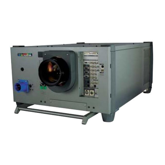
- Page 1 THUNDER 9000gv Super High Brightness Digital Video Projector User Manual...
- Page 2 Precautions: Please read this manual carefully before using your Digital CAUTION: To turn off main power, be sure to remove the plug from Projection THUNDER 9000gv Projector and keep the manual handy power outlet. The power outlet socket should be installed as near to for future reference.
- Page 3 Running Time is Over 750 Hours!!” When you see this message e Do not attempt to stack projectors on the ceiling. please contact your Digital Projection Dealer for a replacement. If the lamp does explode, smoke will be discharged from the vents To Dealer or Installer: located on the side of the unit.
- Page 4 Digital Projection. 4. Manipuler le projecteur avec précautions. Laisser tomber le projecteur 3. Ne pas poser de liquides sur le dessus du projecteur.
- Page 5 89/336/EEC Electromagnetic Compatibility Directive, amended by 92/31/EEC & 93/68/EEC. 73/23/EEC Low Voltage Equipment Directive, amended by 93/68/EEC. Products covered by this Directive Large Screen Projector type THUNDER 9000gv Chassis EURO THUNDER 9000gv Chassis USA Basis on which Conformity is being declared...
-
Page 6: Table Of Contents
TABLE OF CONTENTS Video Adj ................ E-31 INTRODUCTION Noise Reduction ............E-31 Introduction to the 9000gv Projector ........E-1 Color Matrix ............. E-32 Getting Started ............... E-1 Y/C Delay ..............E-32 What's in the Box? ..............E-1 Telecine ..............E-32 Motion Select ............ -
Page 7: Introduction
• DIGITAL PROJECTION’s unique DLP based light engine offers true color reproduction. • The THUNDER 9000gv can accommodate any picture size from 80 to 500 inches (measured diagonally). • The THUNDER 9000gv projects images with uniform brightness while colors remain true to their original source. -
Page 8: Part Names And Functions
1. Part Names and Functions Stacking Pad (4 pcs) Ventilation (out) Remote Sensor PC Card Slot Insert a PC memory card here to upgrade the projector system software or copy data. To access the slot, loosen the screw. AC INPUT Connect the supplied power cable here (AC 200-240V). - Page 9 Controls Remote sensor LENS SHIFT FOCUS ZOOM MENU SELECT ENTER INDICATOR POWER ON/OFF STATUS CANCEL 1. Power Button 6. Cancel Button Press to turn the projector on when the projector is in the standby con- Press this button to exit the menu. Press this button to return the adjust- dition (Main Power switch must be on and the POWER indicator lit or- ments to the last condition while you are in the adjustment or setting ange).
-
Page 10: Terminal Panel
Terminal Panel RGB DIGITAL OUTPUT INPUT9 INPUT3 INPUT2 INPUT1 INPUT4 R/Cr R/Cr OUTPUT OPTION For the optional SD-SDI board. B/Cb B/Cb H/HV H/HV INPUT0 REMOTE1 INPUT5 INPUT6 S-VIDEO1 REMOTE2 VIDEO1 VIDEO2 S-VIDEO2 INPUT7 INPUT8 REMOTE3 E – 4... - Page 11 1. INPUT 3 RGB Connector (Mini D-Sub 15 pin) 7. INPUT 4 Y/Cb/Cr Terminal (RCA) Connect your PC or other analog RGB equipment such as a high-defi- Connect component video outputs (Y/Cb/Cr, Y/Pb/Pr) of the external nition document camera. equipment such as DVD player. This connector accepts RGB signals only.
-
Page 12: Remote Control
7 ADJUST PICTURE Remote Control Press to display the Picture adjustment screen. Pressing this button sequentially selects "Brightness" → "Contrast" → "Saturation" → "Color" → "Hue" → "Sharpness" → "V-Aperture" → "Gamma Correction". 8 IMAGE/PROJECTOR Press to display the Image Option screen. Pressing this button sequen- tially selects "Pixel Adjust"... -
Page 13: Remote Control Precautions
Remote Control Precautions 19 MUTE OSD Press to turn off the on-screen display. Press again to restore the on- • Use the remote control within a distance of about 7m (23feet) and at screen display. an angle of 30˚ above, below, to the left and to the right of the remote NOTE: You can also turn off the on-screen display by pressing and holding CTL control sensor located at the front of the main unit. -
Page 14: Installation
Throw distance for TL- 4Z (LA00109) lens =H x 4.0 - H x 7.0 NOTE: Distances may vary +/- 5%. NOTE: Do not use another optional lens TL-1Z on THUNDER 9000gv. Doing so will not deliver the performance of the projector. -
Page 15: Lens Shift Adjustable Range
Lens Shift Adjustable Range Lens Shift Adjustable Range for Desktop and Ceiling Mount Application The diagram below shows the location of the image position in the lens. The lens can be shifted within the shaded area as shown using the normal projection position as a starting point. -
Page 16: Moving The Projector
Moving The Projector Selecting A Location Always carry your projector by the handle. Ensure that the power cable The further your projector is from the screen or wall, the larger the im- and any other cables connecting to video sources are disconnected age. -
Page 17: Setup
3. SETUP Connecting the Power Cable and Turning on the Projector Before you turn on your projector, ensure that the computer or video source is turned on and that your lens cap is removed. Note: 1. Connect the supplied power cable to the projector. Projector power connector may vary depending upon country. -
Page 18: Set Up The Projector
(2) Press and hold the CTL and press the ZOOM + or - button to adjust the Set up the projector image size optically. You can also adjust the image size by using the ZOOM + or - button on the projector cabinet. 1. -
Page 19: Keystone
Keystone 2) Hookup 2-1. Use the supplied DVI-D cable to connect the RGB DIGITAL output of the master projector to the RGB DIGITAL input (INPUT9 )of the slave projector until all the projectors are connected. Keystone distortion Normal 2-2. Next, using a commercially available, bi-directional RS-232C cable connect the OPTION OUT terminal of the master projector to the OPTION IN terminal of the slave projector until all the projectors are connected. - Page 20 3-1-6-3. Remove the PC card from the slave projector. 6-4-1. Display any signal onto the screen. 6-4-2. Check to see if the images on the master projector are dis- NOTE: If you select the RGB1 input on the master projector, you must select played in synchronization with the ones on the other slave pro- the same input on the slave projector.
-
Page 21: Projector Orientation
• Installing your projector on the ceiling must be done by a qualified An image can be projected from in front or behind a screen, and the technician. Contact your DIGITAL PROJECTION dealer for more projector can be installed on the ceiling*. -
Page 22: Connections
Use common RCA cables (not provided) to connect your VCR or laser Connecting Your PC Or Macintosh Computer disc player to your THUNDER 9000gv Projector. To make these connec- Connecting your PC or Macintosh computer to THUNDER 9000gv tions, simply: Projector will enable you to project your computer's screen image for an impressive presentation. -
Page 23: When Used With One Switcher (Iss-6020/Iss-6020G
When Used with One Switcher (ISS-6020/ISS-6020G) Up to 10 input signals can be accepted when the projector is connected to one Switcher. Using the projector with the Switcher allows easy adjustment and signal selection. RGB DIGITAL OUTPUT INPUT9 INPUT3 INPUT2 INPUT1 INPUT4 R/Cr... - Page 24 NOTE: When Used with Two or More Switchers (100 • Be sure to set all the slide switches (S8603) of the Switcher to RS-422 posi- Inputs) tions. Set the one on the last slave Switcher to the appropriate position to match the connected equipment such as a personal computer.
- Page 25 Set the DIP switch (S8601) of the Switcher as follows: NOTE: Slave numbers 1 to 10 must correspond to the master’s slot numbers 1 to 10. ISS-6020 Setting of S8601 Output to ISS-6020G OPEN Master The Projector 1 2 3 4 5 6 7 8 SHORT OPEN Slave 1...
-
Page 26: Remote 1 Connector
REMOTE 1 Connector This connector is used for either connecting the ISS-6020/ISS-6020G Switcher or a third party external control device (Contact Closure). When the Switcher is used, connect it with the optional control cable (15-15 pin; 50 ft./16m; CTL-6010) to this connector. When used with the Switcher. - Page 27 When used in stand alone operation. Pin No. SHORT/OPEN FUNCTION SHORT External control mode ON External control mode OFF OPEN POWER ON SHORT POWER OFF OPEN PICTURE MUTE ON SHORT OPEN PICTURE MUTE OFF 12pin 8pin 11pin 4pin 4,8,12,11 OPEN OPEN RGB 1 (INPUT 1) OPEN...
-
Page 28: Operating Multiple Projectors With The Remote Control
Operating Multiple Projectors with the Remote Control You can operate multiple projectors with the same remote control in wireless operation. To do so: 1. Select [Advanced Menu] → [Projector Options] → [Setup] → [Page 5] → [Projector ID] and assign an ID number to each projector. See also page E-37. -
Page 29: Using The Rgb Digital Connectors
Using the RGB DIGITAL connectors The Link mode function allows you to adjust or set multiple projectors using the RGB DIGITAL and OPTION connectors. The DVI DIGITAL input accepts up to the XGA (1024 x 768 @85Hz) signal. NOTE: The Auto Adjust feature does not work for DVI digital signal. When DVI signal is selected and the image position is not corrected, adjust the horizontal and vertical position using the Position screen. -
Page 30: Operation
5. OPERATION This section describes how to select a computer or video source, ad- Using The Menus just the picture and sound, edit a signal and adjust all other settings and adjustments for proper projector set-up. 1. Press the MENU button on the remote control to display the menu. 2. -
Page 31: A List Of Direct Key Combinations
A List of Direct Key Combinations CTL+ INPUT (1-10) Switches to any selected signal found in the Entry List. To enable this combination, you must first assign specific remote keys for direct input selection in the Entry Edit window. CTL+ ENTER (While displaying Entry list) Displays the Entry Edit Command window. -
Page 32: Menu Tree
Menu Tree When Switcher Control is turned on: Switcher Brightness Advanced Menu Entry List Contrast Source Select Saturation Adjust (Source) Stand alone Color Ref Adj RGB1 Factory Default RGB2 Sharpness Projector Options RGB3 V-Aperture PC Card Files Component (YCbCr) Gamma Correction Help NTSC, Graphics, Graphics/NTSC, PAL/SECAM2.8, Video1... - Page 33 Keystone Lamp Mode Maximum / Medium / Minimum Advanced Menu Lamp Source Select Ref. White Bal. Adjust (Source) Brightness R/G/B, Contrast R/G/B Ref Adj All Data / Current Signal Factory Default On / Off Timer Execute Switch (Active / Inactive) Including Entry List Projector Options Edit...
-
Page 34: Menu Elements
Menu Elements Title bar Highlight Radio button OK Button Cancel Button Solid triangle Check box Slide bar Menu windows or dialog boxes typically have the following elements: Title bar: Indicates the menu title. Highlight: Indicates the selected menu or item. Solid triangle: Indicates further choices are available. -
Page 35: Menu Descriptions & Functions
Entry List Menu Descriptions & Functions Displays the list of the entry signals. Use the ▲▼ buttons on your re- Source Select mote control or the projector cabinet to select the signal and press the ENTER button on the remote control or the projector cabinet to project the image of the selected source. -
Page 36: Adjust (Source
Select "List" and press ENTER to display the direct Key assignment White Balance list. Select "OK" and press ENTER to close the window. To close the List window, press CANCEL on the remote. Color Temperature This feature adjusts the color temperature using the slide bar. Move the slide bar to the right to increase the color temperature for a bluish image;... -
Page 37: Horizontal/Vertical Position
Horizontal/Vertical Position (when Auto Adjust is off): Video Filter This feature reduces video noise. Select the appropriate filter for your signal. Bar 0 .... Off Adjusts the image location from left to right. Bar 1/3 ..High This adjustment is made automatically when the Auto Adjust is turned Bar 2/3 .. -
Page 38: Color Matrix
Color Matrix Option Adj Clamp Timing: First, select an appropriate color matrix for your input signal, either HDTV or SDTV. Then select an appropriate matrix type from B-Y/R- Y, U/V, Cb/Cr, Pb/Pr or IVX. NOTE: The Color Matrix feature is available for component video signal only. Y/C Delay (not available for RGB) According to the signal, this function sets the detection position (i.e., clamp position) of the black level reproduction of the analog input... -
Page 39: Lens Memory
Lens Memory Switcher (available only when used with ISS-6020) Switcher Gain The Lens Memory function stores the adjusted values when using shift, focus* and zoom buttons on the projector cabinet or the remote control for a specific signal. Example of usage: When a signal with 4:3 aspect ratio and a signal with 5:4 aspect ration both need to be displayed on the 4:3 screen. -
Page 40: Lamp
Lamp Projector Options Lamp Mode Enables you to set preferences and other operating options. This feature allows the lamp power supply to operate under three set- Timer tings. Maximum ..This setting consumes maximum current from the AC input and results in the most light output. Enables you to turn the projector on or off automatically at a specified NOTE: The Maximum mode shortens the lamp life. -
Page 41: Sleep Timer
5. To enable your setting, select Active on the Execute Switch. Menu Display Time This option allows you to select how long the projector waits after the 6. Select OK and press the ENTER button on the remote control to complete last touch of a button to turn off the menu. -
Page 42: Setup
Setup [Page 3] Enables you to set operating options. Press "OK" to save your changes for all the features of Page1, Page2, Page3, Page 4 and Page5. [Page 1] Signal Select (VIDEO 1/2, S-VIDEO1/2 and Switcher) This feature enables you to select composite video standards manu- ally. -
Page 43: Keystone Save/Lens Memory/User Name
Keystone Save Link Mode This option enables you to save your current keystone settings. Saving your change once affects all sources. The changes are saved when you turn off the projector. Lens Memory This feature is used for multiple projector connection using RGB This function applies the stored lens shift, focus, and zoom adjust- Digital Input/Output connectors. -
Page 44: Pc Card Files
PC Card Files Help Displays a list of all the files stored in the PC card so that you can select a file you want to display. You can also sort files by file name or date, or display the file. Although a list of all the files in the PC card is displayed, you can view files in idx, text, HTML, JPEG and BMP format only. -
Page 45: Link Mode
[Page 4] Test Pattern Press to display the test pattern. Pressing this button sequentially se- lects nine test patterns. Selecting a new signal that is close to one of the listed signals in horizontal and vertical frequency Link Mode Selecting a new signal that is close to one of the listed signals in hori- Displaying Current Status of Link Mode zontal and vertical frequency may not display the image correctly be- When selecting the tab "Page 4 ", you will get the following dialog... -
Page 46: Specifications
6. SPECIFICATIONS Optical Panel * .9" x 3 1024 x 768 native resolution up to 1600 x 1200 with advanced AccuBlend Technology Lamp 2.0kW Bubble Type Short Arc Xenon Built in: Overheat Protection Lamp Over-Usage Protection 10000 ANSI Lumens ±10% Light Output Full Light Output at 200- 240V Brightness Uniformity... - Page 47 External Control RS232C (1) D-sub 9 pin Contact Closure Switcher (2) D-sub 15 pin In/Out Addressable Remote Control (wired / wireless) Power Requirement 200-240 VAC, 50/60Hz Input Current 14 A Power Consumption 2.8 kW 9554 per hour Air flow 250 M / hr Air Inlet Underside front centre...
-
Page 48: Optional Accessories
7. Optional Accessories Lens TL-08SF LA00111(Short Focal Lens 0.84) : 10kg TL-1ZH LA00263 (Zoom Lens 1.5 - 2.5:1) : 5.5kg TL-2Z LA00108 (Zoom Lens 2.5 - 4.0:1) : 4.5kg TL-4Z LA00109 (Zoom Lens 4.0 - 7.0:1) : 4.5kg Interface Board SD-SDI BOARD LA00105 Ceiling Mount Kit XL CMKIT LA00264 Switcher... -
Page 49: Compatible Input Signal List
8. Compatible Input Signal List Compatible Input Signal List Signal Name Horizontal Freqency Vertical Frequency [kHz] [Hz] Video(NTSC) 15.734 Video(PAL/SECAM) 15.625 Video (HDTV) 1920x1080i 33.75 Video (HDTV) 1280x720p Video (HDTV) 1920x1080i 26.97 47.95 Video (HDTV) 1920x1080p 26.97 23.98 Video (HDTV) 640x480p 31.5 Video (HDTV) 1080x25p 28.13... -
Page 50: List Of Menu Items Available On Link Mode
List of Menu Items Available on Link Mode See the table below for available functions in the digital link mode and the analog link mode. * The digital signals available in the Link mode are the VESA compatible-signals except interlaced signals of VGA@60Hz to XGA@85Hz. * The VESA compatible signals that can connect to the master projector as analog input and connect to the slave projector as digital output are interlaced signals of SVGA@85Hz, XGA@60Hz, XGA@70Hz, XGA@75Hz and XGA@85Hz. -
Page 51: Appendix
Appendix Dimensions 706 (27.80) 626 (24.65) (2.36) 360 (14.17) 680 (26.77) (0.31) Lens center 43 (1.69) The drawings do not include the lens part. Lens center Unit: mm (inch) E – 45... -
Page 52: Tips On Adjusting Focus For Lens Memory Function
Tips on Adjusting Focus for Lens Memory Function Optimum focus for lens memory function can be achieved on the projector by paying special attention in a few areas. Focus adjustment after the projector has warmed up to normal operating temperature is better than doing so when the projector is cold. Lens mechanics interact differently when adjusting focus from one direction to the other. - Page 53 E – 47...
- Page 54 Printed in Japan 7N8P1511...
Need help?
Do you have a question about the THUNDER 9000gv and is the answer not in the manual?
Questions and answers