Advertisement
Manufacturer:
Model Number(s):
Core Module Versions:
Comments:
Document Revision Date:
O
S
VERVIEW AND
UPPORTED
The DSC MAXSYS Series panels integrate with the g! system using an RS-232 serial connection. The
panel requires the PC4401 Data Interface Module to provide the RS-232 connection to the panel.
Integration of the security system provides monitoring and control from any touch screen, telephone or
computer both locally and remotely. Additionally, events occurring in the security system can trigger
system commands in other sub-systems in the home. For example, a burglar alarm can turn all the lights
on and send out email alerts. The security system can also receive commands as a result of events
within other sub-systems. For example, changing the house mode from Home to Vacation can trigger a
security command to arm the system.
IMPORTANT! This panel requires the PC4020 chip on the main circuit board be version 3.5 or
higher to properly communicate with g!.
Due to possible compatibility issues, the DSC MAXSYS should only be used on COM ports 1 and 2
of the HC-Series System Controllers.
T
HESE PANELS SUPPORT THE FOLLOWING FEATURES
Arm – Disarm: Arm and disarm from the Viewer interface is supported. Status information is available for
all partitions.
Auto Arm: Arming as a System Command from the Event Mapper is supported. By default, automatic
arming is disabled in the Configurator.
Zone Status: Zone status information is available for all zones (in any partition), and is properly shown in
the Viewer.
Zone Bypass: Zones can be bypassed from the g! interface.
History View: The history view is properly supported on any Viewer.
Auto Partition Detection: All available partitions are automatically detected.
Auto Zone Detection: After a zone has been faulted the g! system will automatically detect the zone
number and partition number, but it will not detect the zone name.
T
HESE PANELS DO NOT SUPPORT THE FOLLOWING FEATURES
Auto Name Detection: Zone and partition names cannot be read from the panel.
Arm in Stay Mode: The DSC MAXSYS panels can only be armed in Away mode from the g! interface:
due to a limitation in the DSC RS-232 protocol, it is not possible to arm the panel in Stay mode.
Any feature not specifically noted as supported should be assumed to be unsupported.
ELAN Home Systems ● 1690 Corporate Circle ● Petaluma, CA 94954 USA
tech support: 800.622.3526 • main: 760.710.0990 • sales: 877.289.3526 • email: elan@elanhomesystems.com
©2013 ELAN Home Systems. All rights reserved. ELAN and g! are trademarks of ELAN Home Systems. All other trademarks are the property of their respective owners.
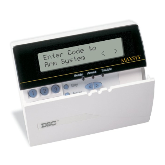
DSC
MAXSYS Series
4.0 (all builds)
1/30/2013
F
EATURES
:
:
Integration Note
Advertisement
Table of Contents

Related Manuals for Elan DSC MAXSYS Series


Summary of Contents for Elan DSC MAXSYS Series
- Page 1 ELAN Home Systems ● 1690 Corporate Circle ● Petaluma, CA 94954 USA tech support: 800.622.3526 • main: 760.710.0990 • sales: 877.289.3526 • email: elan@elanhomesystems.com ©2013 ELAN Home Systems. All rights reserved. ELAN and g! are trademarks of ELAN Home Systems. All other trademarks are the property of their respective owners.
- Page 2 NSTALLATION VERVIEW 1. Mount the PC4401 inside the MAXSYS panel, and connect the PC4401 to the controller according to the DSC documentation. 2. Install and setup the security system. 3. Run a Cat5 wire from the g! system to the security panel and test the cable. 4.
- Page 3 ONNECTION IAGRAM ATERIALS D e v ic e M a nuf a c t ure r P a rt N um be r P ro t o c o l C o nne c t o r T ype N o t e s Co ntro l P anel M A XSYS Series RS-232...
- Page 4 ANEL ROGRAMING Before communication can start between the g! system and the MAXSYS panel, there are several fields that need to be changed in the panel configuration. You will need the installer access code to enter the programming mode. The default code is 5555 for new installations. To enter programming mode, press [*] + [8] + [Installers Code].
- Page 5 C ONFIGURATION ETAILS The following table provides settings used in the g! Configurator when connecting to the DSC MAXSYS Series control panel. Please refer to the Configurator Reference Guide for more details. “<Select>” Select the appropriate item from the list (or drop-down) in the Configurator.
- Page 6 OMMON ISTAKES 1. Failing to test the Cat5 cable assembly. It is easy to make a mistake when terminating the Cat5 cable with the RJ-45 connectors. Always use a LAN tester to check for continuity and shorts. 2. Using a Cat5 patch cable without all 8 conductors. Some Ethernet patch cables only have the 4 conductors (1,2,3,6) needed for Ethernet communications.
Need help?
Do you have a question about the DSC MAXSYS Series and is the answer not in the manual?
Questions and answers