Advertisement
Quick Links
Advertisement

Related Manuals for Veldo Teknoloji v-board

Summary of Contents for Veldo Teknoloji v-board
- Page 1 RANGER Veldo SSH 2019...
-
Page 2: Difficulty Level
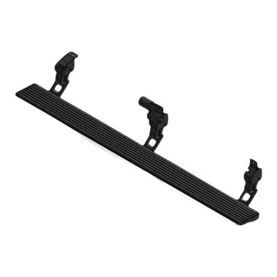
INSTALLATION TIME 3 – 4 HOURS Professional installation recommended DIFFICULTY LEVEL EQUIPMENT LIST ▪ Protective glasses ▪ Ratchet wrench and arms ▪ Cable stripper ▪ Allen wrench set ▪ Electrical insulating strap ▪ Pliers ▪ 8 mm spanner ▪ 13 mm spanner ▪... - Page 3 Parts Front Carrier Foot Motorized Center Carrier Rear Carrier Foot Foot Control Unit Board Veldo SSH 2019...
- Page 4 - Connection Parts M6 x 20 hex socket head bolt x 4 Board profile connection part x 2 M10 x 25 Flanged (Wrench flat 13mm) Bolt x 6 Pieces Note: If the vehicle has a fixed board, its original connecting bolt is used.
- Page 5 Electrical Diagram and Components TWIN ENGINED v - board Back view Rear Engine Socket Front Engine Socket Additional Engine Socket Main Engine Socket *** It is not used in Ford Ranger models. Rear Lightening Front Lightening Socket Socket Veldo SSH 2019...
-
Page 6: Wiring Assembly
- Wiring Assembly Fuse 20A (Fuse 20A) (Fuse 25A) (+12V Feeder) (Red-White) (Brown) Speed information connection.( Optional ) – J2 ( + 12 V ) Step open signal connection ( Optional )- J3 Center Door Switch Rear Door Switch Connection J6 –... - Page 7 - Wiring Assembly LED – 1 connection Front Lightening Socket LED – 2 connection Rear Lightening Socket Front Engine Socket Front Engine Socket ***It is not used in Ford Ranger models. Rear Engine Socket Rear Engine Socket Veldo SSH 2019...
- Page 8 - Wiring Assembly LEFT Before starting installation, the fuse on the wiring is removed. !!!! (Fuse – 25A) (+12V Feeder) (Red-White) **** !!! S1 fuse on the wiring Connect the plus ( + ) end of the wiring to the plus ( + ) end of the battery.
- Page 9 - Wiring Assembly LEFT The battery connection of the end of the wiring is made as shown in the picture. From the original hole of the vehicle located under the driver's mat, the engine and LED ends of the left v_Board wiring are extended to the bottom of the vehicle as shown in the picture.
- Page 10 Connect the minus ( - ) end of the wiring to the chassis of the vehicle. **** !!! Tip J4 on the wiring. Right side v-Board installation, wiring and control unit connection is made in the area shown in the picture on the front passenger side.
- Page 11 - Wiring Assembly LEFT The battery connection of the (+) end of the wiring is made as shown in the picture. From the original hole of the vehicle located under the driver's mat, the engine ends left v_Board installation are extended to the bottom of the vehicle as shown in the picture.
-
Page 12: Mechanical Assembly
- Mechanical Assembly In the installation of carriers on the board, the board profile connection parts are movable in the board channel. By sliding the carrier foot to the installation section, the board is assembled together with the carrier foot. Veldo SSH 2019... - Page 13 - Mechanical Assembly The vehicle's original chassis hole is used for the front carrier foot connection. Note: M10 AA=13mm bolts are used on the vehicle in assembly processes. Veldo SSH 2019...
- Page 14 - Mechanical Assembly The vehicle's original chassis hole is used for the middle carrier foot connection. Note: M10 AA=13mm bolts are used on the vehicle. Veldo SSH 2019...
- Page 15 - Mechanical Assembly The vehicle's original chassis hole is used for the center carrier foot connection. Note: M10 AA=13mm Bolts are used on the vehicle in assembly processes. Veldo SSH 2019...
- Page 16 - Mechanical Assembly The vehicle's original chassis hole is used for rear carrier foot connection. Note: M10 AA=13mm bolts are used on the vehicle in assembly processes. Veldo SSH 2019...
- Page 17 - Mechanical Assembly As shown in the figure, the board is placed on the carrier foots and installed with M6 x 20 hex socket head bolt from the bottom side. Veldo SSH 2019...
- Page 18 - LED Assembly For LED installation, a Ø10 mm hole is drilled with a drill near the connection point of the carrier. For the passage of the LED cable, the hole drilled by a Ø10 mm drill is cut as shown in the figure with the help of an air saw.
- Page 19 After replacing the fuse, check the operation of the v-board. **** !!! Replace fuse S1 **** !!! Make sure that the fuses S1 and S2 are installed in the correct place in the installation. Check the operation of the v – board, opening and closing. Check that the LED light is lit when the door is opened.
- Page 20 - Wiring Assembly_Addition Electrical connections for On & Off position information of right front door. The plastic cover under the right front torpedo, where the vehicle's original signal sockets were located, is removed. white cable in the v_Broard wiring is connected to the white cable in the original...
- Page 21 - Wiring Assembly_Addition Electrical connections for On & Off position information of right rear door. The plastic cover , on the center pole on the right side, where the vehicle's original signal sockets are located, is removed. orange cable in the v_Broard wiring connects to the yellow cable in the original...
- Page 22 - Wiring Assembly_Addition Electrical connections for On & Off position information of left front door. On the left front driver's side, the plastic cover, which is located on the left side of the pedals, where the original signal sockets of the vehicle are located, is removed.
- Page 23 - Wiring Assembly_Addition Electrical connections for On & Off position information of left rear door. On the center pole on the left side , the plastic cover with the vehicle's original signal sockets is removed. orange cable in the v_Broard wiring connects to the green cable in the original...
- Page 24 In adverse conditions, noise may occur due to the compression of parts such as chips, mud, dirt and dust into the V-board. In this case, direct spraying should not be applied to the engines. Set the V - boards manually. After washing, apply silicone spray lubricant to hinges and pins.
-
Page 25: Warranty
- Warranty WARRANTY The warranty written on the v-Board “Veldo Warranty Certificate” is valid for 2 years from the start date. Veldo Warranty Certificate is given to the customer , during product delivery . Our customers are required to present this document in order to make use of the warranty process.
Need help?
Do you have a question about the v-board and is the answer not in the manual?
Questions and answers