Table of Contents
Advertisement
Quick Start
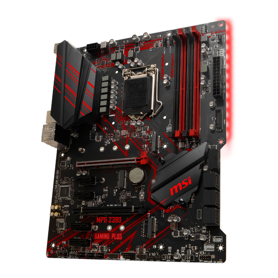
Thank you for purchasing the MSI
MPG Z390 GAMING PLUS
motherboard. This Quick
®
Start section provides demonstration diagrams about how to install your computer.
Some of the installations also provide video demonstrations. Please link to the URL to
watch it with the web browser on your phone or tablet. You may have even link to the
URL by scanning the QR code.
Preparing Tools and Components
Intel
LGA 1151 CPU
®
CPU Fan
Chassis
DDR4 Memory
Power Supply Unit
Graphics Card
Thermal Paste
SATA DVD Drive
SATA Hard Disk Drive
A Package of Screws
Phillips Screwdriver
1
Quick Start
Advertisement
Table of Contents

Related Manuals for MSI MPG Z390 GAMING PLUS


Summary of Contents for MSI MPG Z390 GAMING PLUS
-
Page 1: Quick Start
Quick Start Thank you for purchasing the MSI MPG Z390 GAMING PLUS motherboard. This Quick ® Start section provides demonstration diagrams about how to install your computer. Some of the installations also provide video demonstrations. Please link to the URL to watch it with the web browser on your phone or tablet. -
Page 2: Installing A Processor
Installing a Processor https://youtu.be/4ce91YC3Oww Quick Start... -
Page 3: Installing Ddr4 Memory
Installing DDR4 memory http://youtu.be/T03aDrJPyQs DIMMB2 DIMMB2 DIMMB1 DIMMA2 DIMMA2 DIMMA2 DIMMA1 Quick Start... -
Page 4: Connecting The Front Panel Header
Connecting the Front Panel Header http://youtu.be/DPELIdVNZUI Power LED Power Switch JFP1 Reserved HDD LED Reset Switch HDD LED + Power LED + HDD LED - Power LED - Reset Switch Power Switch Reset Switch Power Switch JFP1 Reserved No Pin HDD LED - HDD LED HDD LED +... -
Page 5: Installing The Motherboard
Installing the Motherboard BAT1 Quick Start... -
Page 6: Installing Sata Drives
Installing SATA Drives http://youtu.be/RZsMpqxythc Quick Start... -
Page 7: Installing A Graphics Card
Installing a Graphics Card http://youtu.be/mG0GZpr9w_A Quick Start... -
Page 8: Connecting Peripheral Devices
Connecting Peripheral Devices Quick Start... -
Page 9: Connecting The Power Connectors
Connecting the Power Connectors http://youtu.be/gkDYyR_83I4 ATX_PWR1 CPU_PWR1 Quick Start... -
Page 10: Power On
Power On Quick Start... -
Page 11: Table Of Contents
Contents Quick Start ......................1 Preparing Tools and Components ................1 Installing a Processor ..................... 2 Installing DDR4 memory ..................3 Connecting the Front Panel Header ............... 4 Installing the Motherboard ..................5 Installing SATA Drives..................... 6 Installing a Graphics Card ..................7 Connecting Peripheral Devices ................ - Page 12 Installing Windows 10 ..................36 ® Installing Drivers ....................36 Installing Utilities ....................36 BIOS Setup ......................37 Entering BIOS Setup ..................... 37 Resetting BIOS ...................... 38 Updating BIOS ....................... 38 EZ Mode ........................ 39 Advanced Mode ....................41 SETTINGS ......................42 Advanced .......................
-
Page 13: Specifications
* M.2 slots and SATA ports share the bandwidth. Please refer to page 28 for details. ** Before using Intel Optane™ memory modules, please ensure that you have ® updated the drivers and BIOS to the latest version from MSI website. Continued on next page Specifications... - Page 14 Continued from previous page Intel Z390 Chipset ® y Supports RAID 0, RAID1, RAID 5 and RAID 10 for SATA RAID storage devices y Supports RAID 0, RAID 1 for M.2 PCIe storage devices y 1x Intel I219-V Gigabit LAN controller ®...
- Page 15 Continued from previous page y 1x 24-pin ATX main power connector y 1x 8-pin ATX 12V power connector y 6x SATA 6Gb/s connectors y 3x M.2 slots (2 M-Key slots,1 E-Key slot) y 2x USB 3.1 Gen1 connectors (supports additional 4 USB 3.1 Gen1 ports) y 2x USB 2.0 connectors (supports additional 4 USB 2.0 ports)
- Page 16 Continued from previous page y Drivers y DRAGON CENTER y MYSTIC LIGHT y Open Broadcaster Software (OBS) Software y CPU-Z MSI GAMING y Intel Extreme Tuning Utility ® y Google Chrome™ ,Google Toolbar, Google Drive y Norton™ Internet Security Solution...
- Page 17 Continued from previous page y Audio ƒ Audio Boost y Network ƒ GAMING LAN with GAMING LAN Manager ƒ Intel CNVi Ready y Storage ƒ Twin Turbo M.2 y Cooling ƒ Extended Heastink Design ƒ Pump Fan ƒ GAMING Fan Control y LED ƒ...
-
Page 18: Package Contents
Package contents Please check the contents of your motherboard package. It should contain: Motherboard MPG Z390 GAMING PLUS Cable SATA 6Gb/s Cables M.2 Screw I/O Shield Accessories Case Badge VIP Card Application DVD Driver DVD User Manual Documentation Quick Installation Guide Important If any of the above items are damaged or missing, please contact your retailer. -
Page 19: Block Diagram
Block Diagram HDMI DVI-D 2 Channel DDR4 Memory Processor PCIe Bus PCIe Bus DMI 3.0 2x M.2 4x PCIe x1 1x M.2 6x SATA 6Gb/s (E Key for Intel wireless -AC (CNVi ) module only) 2x USB 3.1 Gen2 6x USB 3.1 Gen1 Intel I219-V 6x USB 2.0... -
Page 20: Rear I/O Panel
Rear I/O Panel Audio Ports PS/2 USB 3.1 Gen2 DVI-D USB 2.0 USB 3.1 Gen2 Type-C USB 3.1 Gen1 LAN Port LED Status Table Link/ Activity LED Speed LED Status Description Status Description No link 10 Mbps connection Yellow Linked Green 100 Mbps connection Blinking... -
Page 21: Realtek Audio Console
Realtek Audio Console After Realtek Audio Console is installed. You can use it to change sound settings to get better sound experience. Application Enhancement Advanced Settings Device Selection Main Volume Connector Settings Jack Status y Device Selection - allows you to select a audio output source to change the related options. - Page 22 Audio jacks to headphone and microphone diagram Audio jacks to stereo speakers diagram AUDIO INPUT Audio jacks to 7.1-channel speakers diagram AUDIO INPUT Rear Front Side Center/ Subwoofer Rear I/O Panel...
-
Page 23: Overview Of Components
Overview of Components CPU Socket DIMMA1 SYS_FAN1 DIMMA2 DIMMB1 CPU_FAN1 DIMMB2 CPU_PWR1 PUMP_FAN1 JRGB2 SYS_FAN5 ATX_PWR1 JUSB4 M2_1 PCI_E1 JUSB3 BAT1 PCI_E2 CNVI_1 SATA▼1▲2 PCI_E3 JBAT1 SATA▼3▲4 PCI_E4 SATA▼5▲6 PCI_E5 M2_2 PCI_E6 JAUD1 JRGB1 JFP1 SYS_FAN2 JUSB2 SYS_FAN3 JUSB1 SYS_FAN4 JCI1 JTPM1 JFP2... - Page 24 Component Contents Port Name Port Type Page CPU_FAN1, PUMP_FAN1, SYS_FAN1~5 Fan Connectors CPU_PWR1, ATX_PWR1 Power Connectors CPU Socket LGA1151 CPU Socket DIMMA1/A2/B1/B2 DIMM Slots JAUD1 Front Audio Connector JBAT1 Clear CMOS Jumper JCI1 Chassis Intrusion Connector JCOM1 Serial Port Connector JFP1, JFP2 Front Panel Connectors JRGB1, JRGB2...
-
Page 25: Cpu Socket
Always unplug the power cord from the power outlet before installing or removing the CPU. Please retain the CPU protective cap after installing the processor. MSI will deal with Return Merchandise Authorization (RMA) requests if only the motherboard comes with the protective cap on the CPU socket. -
Page 26: Dimm Slots
DIMM Slots DIMMA1 DIMMB1 Channel A Channel B DIMMA2 DIMMB2 Memory module installation recommendation DIMMB2 DIMMB2 DIMMB1 DIMMA2 DIMMA2 DIMMA2 DIMMA1 Important Always insert memory modules in the DIMMA2 slot first. Due to chipset resource usage, the available capacity of memory will be a little less than the amount of installed. -
Page 27: Pci_E1~6: Pcie Expansion Slots
PCI_E6: PCIe 3.0 x1 (PCH lanes) Important If you install a large and heavy graphics card, you need to use a tool such as MSI Gaming Series Graphics Card Bolster to support its weight and to prevent deformation of the slot. -
Page 28: M2_1~2: M.2 Slots (Key M)
M2_1~2: M.2 Slots (Key M) Important Intel RST only supports PCIe M.2 SSD with UEFI ROM. ® Intel Optane™ Memory Ready. ® M2_1 Video Demonstration Watch the video to learn how to Install M.2 module. M2_2 http://youtu.be/JCTFABytrYA Installing M.2 device 1. -
Page 29: Jfp1, Jfp2: Front Panel Connectors
JFP1, JFP2: Front Panel Connectors These connectors connect to the switches and LEDs on the front panel. Power LED Power Switch JFP1 Reserved HDD LED Reset Switch HDD LED + Power LED + HDD LED - Power LED - Reset Switch Power Switch Reset Switch Power Switch... -
Page 30: Cpu_Pwr1, Atx_Pwr1: Power Connectors
CPU_PWR1, ATX_PWR1: Power Connectors These connectors allow you to connect an ATX power supply. CPU_PWR1 Ground +12V Ground +12V Ground +12V Ground +12V +3.3V +3.3V +3.3V -12V Ground Ground PS-ON# Ground Ground Ground ATX_PWR1 Ground Ground PWR OK 5VSB +12V +12V +3.3V Ground... -
Page 31: Jusb1~2: Usb 2.0 Connectors
Note that the VCC and Ground pins must be connected correctly to avoid possible damage. In order to recharge your iPad,iPhone and iPod through USB ports, please install MSI Dragon Center utility. The CNVI_1 and JUSB2 share the same bandwidth. And one USB port connecting to JUSB2 is unavailable when the CNVI_1 slot has been installed. -
Page 32: Cpu_Fan1, Pump_Fan1, Sys_Fan1~5: Fan Connectors
CPU_FAN1, PUMP_FAN1, SYS_FAN1~5: Fan Connectors Fan connectors can be classified as PWM (Pulse Width Modulation) Mode or DC Mode. PWM Mode fan connectors provide constant 12V output and adjust fan speed with speed control signal. DC Mode fan connectors control fan speed by changing voltage. You can follow the instruction below to adjust the fan connector to PWM or DC Mode. -
Page 33: Jaud1: Front Audio Connector
JAUD1: Front Audio Connector This connector allows you to connect audio jacks on the front panel. MIC L Ground MIC R Head Phone R MIC Detection SENSE_SEND No Pin Head Phone L Head Phone Detection JCI1: Chassis Intrusion Connector This connector allows you to connect the chassis intrusion switch cable. Normal Trigger the chassis intrusion event... -
Page 34: Jtpm1: Tpm Module Connector
JTPM1: TPM Module Connector This connector is for TPM (Trusted Platform Module). Please refer to the TPM security platform manual for more details and usages. LPC Clock 3V Standby power LPC Reset 3.3V Power LPC address & data pin0 Serial IRQ LPC address &... -
Page 35: Jrgb1, Jrgb2: Rgb Led Connectors
Always turn off the power supply and unplug the power cord from the power outlet before installing or removing the LED strip. Please use MSI’ s software to control the extended LED strip. EZ Debug LED These LEDs indicate the debug status of the motherboard. -
Page 36: Installing Os, Drivers & Utilities
Installing OS, Drivers & Utilities Please download and update the latest utilities and drivers at www.msi.com ® Installing Windows 1. Power on the computer. 2. Insert the Windows ® 10 installation disc/USB into your computer. 3. Press the Restart button on the computer case. -
Page 37: Bios Setup
Press Delete key, when the Press DEL key to enter Setup Menu, F11 to enter Boot Menu message appears on the screen during the boot process. y In MSI Dragon Center application, click on GO2BIOS button and choose OK. The system will reboot and enter BIOS setup directly. -
Page 38: Resetting Bios
Updating BIOS Updating BIOS with M-FLASH Before updating: Please download the latest BIOS file that matches your motherboard model from MSI website. And then save the BIOS file into the USB flash drive. Updating BIOS: 1. Insert the USB flash drive that contains the update file into the USB port. -
Page 39: Ez Mode
EZ Mode At EZ mode, it provides the basic system information and allows you to configure the basic setting. To configure the advanced BIOS settings, please enter the Advanced Mode by pressing the Setup Mode switch or F7 function key. XMP switch Setup Mode switch Screenshot... - Page 40 y Information display - click on the CPU, Memory, Storage, Fan Info and Help buttons on left side to display related information. y Function buttons - enable or disable the LAN Option ROM, M.2/ Optane Genie, HD audio controller, AHCI/ RAID, CPU Fan Fail Warning Control and BIOS Log Review by clicking on their respective button.
-
Page 41: Advanced Mode
Advanced Mode Press Setup Mode switch or F7 function key can switch between EZ Mode and Advanced Mode in BIOS setup. XMP switch Setup Mode switch Screenshot Search Language System information GAME BOOST switch Boot device priority bar BIOS menu BIOS menu selection selection... -
Page 42: Settings
SETTINGS System Status f System Date Sets the system date. Use tab key to switch between date elements. The format is <day> <month> <date> <year>. <day> Day of the week, from Sun to Sat, determined by BIOS. Read-only. <month> The month from Jan. through Dec. <date>... - Page 43 fPEG X - Max Link Speed [Auto] Sets PCI Express protocol of PCIe x16 slots for matching different installed devices. [Auto] This item will be configured automatically by BIOS. [Gen1] Enables PCIe Gen1 support only. [Gen2] Enables PCIe Gen2 support only. [Gen3] Enables PCIe Gen3 support only.
- Page 44 fIpv4 PXE Support [Enabled] When Enabled, the system UEFI network stack will support Ipv4 protocol. This item will appear when Network Stack is enabled. [Enabled] Enables the Ipv4 PXE boot support. [Disabled] Disables the Ipv4 PXE boot support. fIpv6 PXE Support [Enabled] When Enabled, the system UEFI network stack will support Ipv6 protocol.
- Page 45 fIGD Multi-Monitor [Disabled] Enables or disables the multi-screen output from integrated graphics and external graphics card. This item appears when Initiate Graphic Adapter set to PEG. [Enabled] Enables multi-screen function for both integrated and external graphics cards. [Disabled] Disables this function. f USB Configuration Sets the onboard USB controller and device function.
- Page 46 Disables this function. fMSI Fast Boot [Disabled] MSI Fast Boot is the fastest way to boot the system. It will disable more devices to speed up system boot time which is faster than the boot time of Fast Boot. [Enabled] Enables the MSI Fast Boot function to speed up booting time.
- Page 47 fSecure Boot Sets the Windows secure boot to prevent the unauthorized accessing. Press Enter to enter the sub-menu. This sub-menu will appear when Windows 10 WHQL Support is enabled. fSecure Boot Support [Disabled] Enables or disables secure boot support. [Enabled] Enables the secure boot function and allow you to set the secure boot settings.
-
Page 48: Boot
fResume By Intel Onboard LAN/ CNVI [Disabled] Enables or disables the system wake up by Onboard Intel LAN/ CNVI. [Enabled] Enables the system to be awakened from the power saving modes when activity or input signal of Intel LAN/ CNVI device is detected. [Disabled] Disables this function. -
Page 49: Security
[Enabled] The system boots straight to the BIOS setup by long pressing the power button about 4 seconds when the system is off. [Disabled] Disables this function. f Bootup NumLock State [On] Select the keyboard NumLock state upon bootup. f Info Block effect [Unlock] Sets the state of Help information block. -
Page 50: Save & Exit
Important When selecting the Administrator / User Password items, a password box will appear on the screen. Type the password then press <Enter>. The password typed now will replace any previous set password from CMOS memory. You will be prompted to confirm the password. - Page 51 Important Overclocking your PC manually is only recommended for advanced users. Overclocking is not guaranteed, and if done improperly, it could void your warranty or severely damage your hardware. If you are unfamiliar with overclocking, we advise you to use GAME BOOST function for easy overclocking.
- Page 52 f GT Ratio [Auto] Sets the integrated graphics ratio. The valid value range depends on the installed CPU. f Adjusted GT Frequency Shows the adjusted integrated graphics frequency. Read-only. f Misc Setting* Press Enter, + or - key to open or close the following 3 items related to CPU features. fEIST [Enabled]* Enables or disables the Enhanced Intel SpeedStep Technology.
- Page 53 f Adjusted DRAM Frequency Shows the adjusted DRAM frequency. Read-only. f Memory Try It ! [Disabled] It improve memory compatibility or performance by choosing optimized memory preset. f Advanced DRAM Configuration Press Enter to enter the sub-menu. User can set the memory timing for each/ all memory channel.
- Page 54 fCPU Technology Support Press Enter to enter the sub-menu. The sub-menu shows the key features of installed CPU. Read only. f MEMORY-Z Press Enter to enter the sub-menu. This sub-menu displays all the settings and timings of installed memory. You can also access this information menu at any time by pressing [F5].
- Page 55 fHardware Prefetcher [Enabled] Enables or disables the hardware prefetcher (MLC Streamer prefetcher). [Enabled] Allows the hardware prefetcher to automatically pre-fetch data and instructions into L2 cache from memory for tuning the CPU performance. [Disabled] Disables the hardware prefetcher. fAdjacent Cache Line Prefetch [Enabled] Enables or disables the CPU hardware prefetcher (MLC Spatial prefetcher).
- Page 56 fCFG Lock [Enabled] Lock or un-lock the MSR 0xE2[15], CFG lock bit. [Enabled] Locks the CFG lock bit. [Disabled] Un-locks the CFG lock bit. fEIST [Enabled] Enables or disables the Enhanced Intel SpeedStep Technology. This item will ® appear when OC Explore Mode is set to Normal. [Enabled] Enables the EIST to adjust CPU voltage and core frequency dynamically.
-
Page 57: M-Flash
M-FLASH provides the way to update BIOS with a USB flash drive. Please down-load the latest BIOS file that matches your motherboard model from MSI website, save the BIOS file into your USB flash drive. And then follow the steps below to update BIOS. -
Page 58: Oc Profile
OC PROFILE f Overclocking Profile 1/ 2/ 3/ 4/ 5/ 6 Overclocking Profile 1/ 2/ 3/ 4/ 5/ 6 management. Press <Enter> to enter the sub- menu. fSet Name for Overclocking Profile 1/ 2/ 3/ 4/ 5/ 6 Name the current overclocking profile. fSave Overclocking Profile 1/ 2/ 3/ 4/ 5/ 6 Save the current overclocking profile. -
Page 59: Hardware Monitor
HARDWARE MONITOR Temperature & Speed Fan Manage Setting Buttons Temperature/ Voltage display f Temperature & Speed Shows the current CPU temperature, system temperature and fans' speeds. f Fan Manage ƒ PWM - allows you to select the PWM mode for fan operation. ƒ... -
Page 60: Mystic Light
MYSTIC LIGHT MYSTIC LIGHT is an application that allows you to control LED light effects of MSI & partner products. For some earlier products, you can go to product download page to download the applicable LED control software. Device LED effect control screen When you start up MYSTIC LIGHT, there will be a list of auto-detected devices on the top of the screen. - Page 61 y LED area selector - allows you to select the LED area on the device. The LED effects vary depending on your LED area selection. y Effect speed level - allows you to adjust the LED light effect switching speed. Please note that this function will only be available if your device supports it.
- Page 62 ƒ Synchronize all - There is a quick button on the upper right that allows you to synchronize all your devices with one click. Click the All Sync button, then the chain icons under all sync devices will be changed in red-chain icons and the Profile control panel will appear on the left.
-
Page 63: Raid Configuration
RAID Configuration Below are the different types of a RAID. RAID 0 breaks the data into blocks which are written to separate hard drives. Spreading the hard drive I/O load across independent channels greatly improves I/O performance. RAID 1 provides data redundancy by mirroring data between the hard drives and provides enhanced read performance. -
Page 64: Creating Raid Volume
6. Press F10 to save configuration and exit, and then reboot and press Delete key to enter BIOS Setup menu. 7. Go to BIOS > SETTING > Advanced > Intel(R) Rapid Storage Technology sub- menu. Creating RAID Volume 1. As previously mentioned, enable Intel(R) Rapid Storage Technology. 2. -
Page 65: Removing A Raid Volume
Removing a RAID Volume Here you can delete the RAID volume, but please be noted that all data on RAID drives will be lost. Important If your system currently boots to RAID and you delete the RAID volume, your system will become unbootable. -
Page 66: Resetting Disks To Non-Raid
Resetting Disks to Non-RAID 1. Go to BIOS > SETTING > Advanced > Intel(R) Rapid Storage Technology. 2. Select the RAID volume from the Intel(R) Rapid Storage Technology screen to enter the RAID VOLUME INFO screen. 3. Select the disk and press Enter to enter PHYSICAL DISK INFO screen. 4. -
Page 67: Rebuilding Raid Array
Rebuilding RAID Array A RAID 1, RAID 5 or RAID 10 volume is reported as Degraded when one of its hard drive members fails or is temporarily disconnected, and data mirroring is lost. As a result, the system can only utilize the remaining functional hard drive member. To re-establish data mirroring and restore data redundancy, refer to the procedure below that corresponds to the current situation. -
Page 68: Installing Raid Driver
2. When prompted, insert the USB flash drive with Intel RAID Drivers and then click Browse. ƒ To make an Intel RAID Drivers USB flash drive. Insert the MSI Driver Disc into the optical drive. Copy all the contents in \\Storage\Intel\16.x\f6flpy-x64 3. -
Page 69: Intel ® Optane™ Memory Configuration
® ˜ Reboot to operating system. ˜ Insert the MSI Driver Disc into the optical drive. ˜ Click the Select to choose what happens with this disc pop-up notification, then select Run DVDSetup.exe to open the installer. If you turn off the AutoPlay feature from the Windows Control Panel, you can still manually execute the DVDSetup.exe from the root path of the MSI Driver Disc. - Page 70 5. Enable Intel Optane™ Memory. ® ˜ Run the Intel Rapid Storage Technology software. ® ˜ Click Intel Optane™ Memory tab and click Enable. ® ˜ Click Yes in the dialog. 6. Reboot System. WARNING Once you enable Intel Optane™ memory, in order to prevent seriously damage your ®...
-
Page 71: Removing The Intel ® Optane™ Memory
Removing the Intel Optane™ memory ® If you no longer want to use Intel Optane™ memory, you have to disable the Intel ® ® Optane™ memory before removing the Intel Optane™ memory module to avoid ® operating system damage. Please follow the steps below to remove the Intel Optane™... -
Page 72: Troubleshooting
Troubleshooting Lost BIOS password Before sending the motherboard for RMA repair, try to go over troubleshooting y Clear the CMOS, but that will cause guide first to see if your got similar you to lose all customized settings in the symptoms as mentioned below. -
Page 73: Regulatory Notices
이 기기는 가정용(B급) 전자파적합기기로서 주 y Visit the MSI website and locate a nearby distributor 로 가정에서 사용하는 것을 목적으로 하며, 모 for further recycling information. 든 지역에서 사용할 수 있습니다. - Page 74 Unión Europea al final de su periodo de vida. Usted their useful life. MSI will comply with the product take debe depositar estos productos en el punto limpio...
- Page 75 Products designed to be operated del suo ciclo di vita. MSI si adeguerà a tale Direttiva at closer proximities, such as tablet computers, ritirando tutti i prodotti marchiati MSI che sono stati comply with applicable EU requirements in typical venduti all’interno dell’Unione Europea alla fine del...
- Page 76 Micro-Star Int’ l Co., Ltd. All other marks and names mentioned may be trademarks of their respective owners. No warranty as to accuracy or completeness is expressed or implied. MSI reserves the right to make changes to this document without prior notice. Technical Support...
Need help?
Do you have a question about the MPG Z390 GAMING PLUS and is the answer not in the manual?
Questions and answers