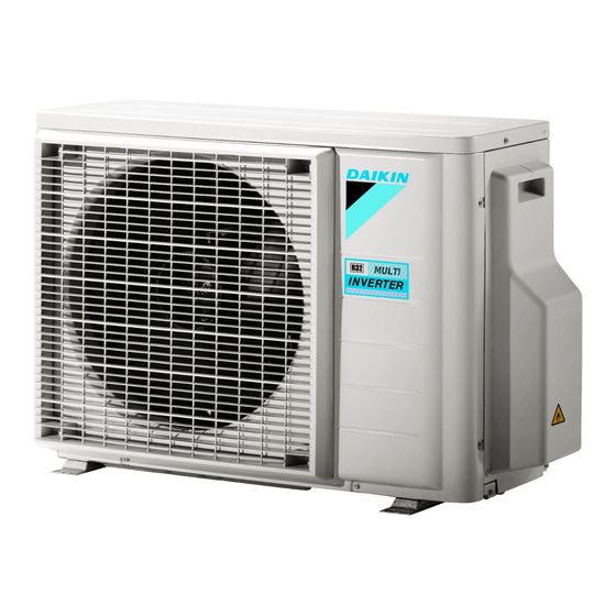
Summary of Contents for Daikin 2MXM-N9
- Page 1 Installation manual R32 Split series 2AMXM40M4V1B9 2AMXM50M4V1B9 2AMXF40A2V1B 2AMXF50A2V1B 2MXF40A2V1B 2MXF50A2V1B Installation manual 2MXM40N2V1B9 English R32 Split series 2MXM50N2V1B9...
- Page 2 3P475203-15M...
- Page 3 2P427092-17W...
- Page 4 2P427092-17W...
- Page 5 3P475203-17M...
- Page 6 2P427092-19W...
- Page 7 2P427092-19W...
- Page 8 3P475203-19M...
- Page 9 2P630134-5C...
- Page 10 2P630134-5C...
-
Page 11: Table Of Contents
About heat mode lock..............20 Daikin website (publicly accessible). 9.3.1 To turn on heat mode lock .......... 20 ▪ The full set of latest technical data is available on the Daikin About standby electricity saving function ........20 Business Portal (authentication required). 9.4.1 To turn on standby electricity saving function ..... - Page 12 2 Specific installer safety instructions Installation site (see "4.1 Preparing the installation site" [ 4 13]) Checking the refrigerant piping ("5.3 Checking the refrigerant piping" [ 4 16]) CAUTION DANGER: RISK OF EXPLOSION ▪ Check if the installation location can support the unit's Do NOT start the unit if it is vacuumed. weight.
-
Page 13: About The Box
3 About the box WARNING Preparing the installation site Do NOT connect the power supply to the indoor unit. This WARNING could result in electrical shock or fire. The appliance shall be stored in a room without WARNING continuously operating ignition sources (example: open flames, an operating gas appliance or an operating electric ▪... -
Page 14: Additional Installation Site Requirements Of The Outdoor Unit In Cold Climates
4 Unit installation Note: If the sound is measured under actual installation conditions, the measured value might be higher than the sound pressure level mentioned in "Sound spectrum" in the data book due to environmental noise and sound reflections. INFORMATION The sound pressure level is less than 70 dBA. -
Page 15: Piping Installation
5 Piping installation Hose (field supply) 5.1.3 Refrigerant piping length and height difference The shorter the refrigerant piping, the better the performance of the Piping installation system. The piping length and height differences must comply with the Preparing refrigerant piping following requirements. -
Page 16: To Connect The Refrigerant Piping To The Outdoor Unit
5 Piping installation Port Class Reducer WARNING 25, 35 — Connect the refrigerant piping securely before running the compressor. If the refrigerant piping is NOT connected and 2MXF40 the stop valve is open when the compressor is run, air will 20, 25, 35 —... -
Page 17: Charging Refrigerant
6 Charging refrigerant 1 Vacuum the system until the pressure on the manifold indicates WARNING −0.1 MPa (−1 bar). The refrigerant inside the unit is mildly flammable, but 2 Leave as is for 4-5 minutes and check the pressure: normally does NOT leak. If the refrigerant leaks in the room and comes in contact with fire from a burner, a If the pressure…... -
Page 18: Electrical Installation
7 Electrical installation Contains fluorinated greenhouse gases DANGER: RISK OF ELECTROCUTION RXXX All electrical parts (including thermistors) are powered by GWP: XXX the power supply. Do not touch them with bare hands. DANGER: RISK OF ELECTROCUTION Disconnect the power supply for more than 10 minutes, GWP ×... -
Page 19: Finishing The Outdoor Unit Installation
8 Finishing the outdoor unit installation Finishing the outdoor unit installation To finish the outdoor unit installation DANGER: RISK OF ELECTROCUTION ▪ Make sure that the system is earthed properly. 2× ▪ Turn off the power supply before servicing. ▪ Install the switch box cover before turning on the power supply. -
Page 20: About Night Quiet Mode
9 Configuration 9.3.1 To turn on heat mode lock 1 Remove the top plate (2 screws) and the front plate (8 screws). 2 To set heat mode lock remove the S99 connector. 3 To reset the heat pump mode (cooling/heating), plug the connector back. -
Page 21: Commissioning
▪ A subset of the latest technical data is available on the regional Daikin website (publicly accessible). To perform a wiring check. ▪ The full set of latest technical data is available on the Daikin Business Portal (authentication required). 2(A)MXM40+50 + 2(A)MXF40+50... -
Page 22: Wiring Diagram
12 Technical data 12.1 Wiring diagram Symbol Meaning Coil Reactor 12.1.1 Unified wiring diagram legend Stepper motor For applied parts and numbering, refer to the wiring diagram on the Compressor motor unit. Part numbering is by Arabic numbers in ascending order for each part and is represented in the overview below by "*"... -
Page 23: Piping Diagram: Outdoor Unit
12 Technical data ▪ High pressure switches: category IV 12.2 Piping diagram: Outdoor unit ▪ Compressor: category II Component PED category classification: ▪ Other components: refer to PED article 4, paragraph 3 2MXM50, 2AMXM50, 2AMXF50, 2MXF50 7.9CuT 6.4CuT 6.4CuT (6.4CuT) 7.9CuT 6.4CuT 6.4CuT... - Page 24 3P600450-3G 2021.03 Verantwortung für Energie und Umwelt...


Need help?
Do you have a question about the 2MXM-N9 and is the answer not in the manual?
Questions and answers