Advertisement
Quick Links
Advertisement

Related Manuals for Model Train Technology Signal Controller


Summary of Contents for Model Train Technology Signal Controller
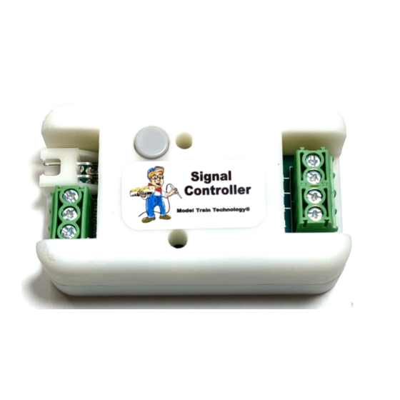
- Page 1 Signal Controller™ OPERATIONS MANUAL Version 1.1b April 2021...
- Page 2 April 2021...
- Page 3 INTRODUCTION The Model Train Technology™ Signal Controller™ provides an extremely simple plug-and-play system for lighting and animating layout block signals and RR Crossing Flashers. After years of running block signaling from the computer via train software, I decided that for my 4x8’ demo layout I wanted a very simple system that gives the appearance of a much more sophisticated operation –...
- Page 4 OVERVIEW Each MTT Signal Controller (“Controller”) stands on its own and is triggered by a sensor, either under the track or mounted on the side of the track. Our Precision Detector™ is a great choice since it is not based on IR (infrared) and is therefore not impacted by difficult lighting conditions.
- Page 5 The Controller has three outputs that are synchronized to a behavior. You can adjust the brightness of each of the output individually. This lets you set the brightness appropriate to your layout. You can also individually adjust each of the different colored LEDS.
- Page 6 • Red, fade to Yellow, fade to Green • Alternate flash Red & Green (speed adjustable) * • Alternate flash R & G with fade (speed adjustable) * *For use with gate crossings There are two types of controller. One type is for LEDs and the other is for Fiber Cable lit block signals.
-
Page 7: Setup And Operation
SETUP AND OPERATION The Controller setup is simple. Connect to a 5-12VDC power source (or DCC power) to the topmost JST terminals as shown above. Connect your Signal LEDs as shown on the right. The LEDs can be common Cathode or Common Anode. Common Cathode means the COMMON is negative (usually the black wire, but not always). - Page 8 If you have another kind of sensor system you can either have them share the same power supply or use the GROUND terminal. You may also “short” the ground and the signal to create the same result. In other words, a simple mechanical switch between SIGNAL and GROUND will trip the Controller.
- Page 9 SELECTING THE BEHAVIOR SPEED The behavior speed adjustment screw is inside the Controller. You access it with the provided 2mm screwdriver. Gently turn the screw inside from zero to about 300 degrees. It does not turn 360 degrees. Left or counterclockwise is faster (less time between stages), right or clockwise increases the time between stages.
- Page 10 for adjustment to the Green LED. Once you are set with the Green LED brightness setting, press the select button one final time. After the final press, all three LEDs will flash and turn off. After that and depending on the behavior setting, one of two things will happen: 1.
- Page 11 CROSSING GATE LIGHT SETTINGS The speed of the alternate flashing can be adjusted by turning the speed adjustment screw. It adjusts the time between stages just as before but in this case, it is the speed of the back and forth of the two output ports (red and green).
- Page 12 April 2021...
- Page 13 April 2021...
- Page 14 DCC OPERATIONS The Controller can respond DCC Accessory messages just like your turnout controllers. You can set the Controller to the SAME address as a turnout so that when you change the turnout, the Controller automatically changes the color of the signal. You can also configure several Controllers to the same switch address so that multiple but different signal lights will light according to your layout design.
- Page 15 To operate the Controller with DCC you must power and connect your DCC rails A & B to the Controller. For small and medium sized layouts this should not be a problem since the Controller and LED require about 30ma each to run. For larger layouts or layouts with a lot of signals connected to you DCC track we suggest you create a separate Booster zone.
- Page 16 To exit setting the address mode WITHOUT changing it, press the select button once. The Controller will return to its ready state. As soon as you select CLOSED or THROWN, the Controller will flash 4 times and the lights will go off. The Controller is now set to the new address.
- Page 17 ELECTRONICS AND STATIC ELECTRICITY The MTT PRECISION DETECTOR™ - Trackside circuit board and components are exposed when the cover is off. Static electricity can cause component failure. Scuffing along a carpet and then touching one of the component connectors can cause a static spark. These components are fairly rugged –...
- Page 18 ONE YEAR MANUFACTURER WARRANTY : We warrant this product to be free from defects in workmanship and materials, under normal residential use and conditions, for a period of one (1) year for the original invoice date. Shipping and handling fees are to be paid for by the customer. LIMITATION OF LIABILITY UNDER NO CIRCUMSTANCE SHALL COMPANY OR ITS AFFILIATES, PARTNERS, SUPPLIERS OR LICENSORS BE LIABLE...
- Page 19 Signal Controller and Magnetic Bracket April 2021...
- Page 20 Model Train Technology LLC 10524 Moss park Rd. Ste. 204-256 Orlando, Florida 32832 407-242-5436 www.ModelTrainTechnology.com support@modeltraintechnology.com Version 1.1b Copyright© 2021 Model Train Technology LLC April 2021...
Need help?
Do you have a question about the Signal Controller and is the answer not in the manual?
Questions and answers