Advertisement
Quick Links
Advertisement

Related Manuals for Model Train Technology II Series


Summary of Contents for Model Train Technology II Series
- Page 1 PASSENGER CAR LIGHTING with DCC DECODER OPERATIONS MANUAL SERIES II Version 2.01 January 2021...
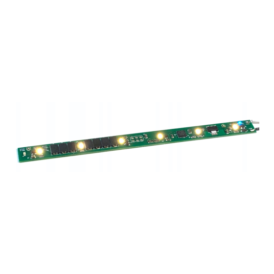
- Page 2 The N & HO Scale LED light boards (with DCC Decoder) have either 5, 6, 8, 11 or 22 built-in LEDs and pads (MAIN and (AUX) to connect two additional LEDs that are typically used for red end-of-car lighting. The Decoder has a Microprocessor (MCU) and the board behaves like an engine decoder (NMRA Multi-Function Decoder) using the function keys and speed control for brightness adjustments and address setting.
- Page 3 1. Connect you board to you DCC main power supply. Make sure you are not connected to the programming lines. This works with the main track power. As part of our ongoing inventive spirit we recently we began including a solid-state (non-mechanical) magnetic sensor on the board at the same end as the push button switch.
-
Page 4: Function Keys
OPERATIONS: FUNCTION KEYS F0-F4 Turn on the lights to the default brightness. If this is a new board, or you performed a RESET, the brightness will be 80% Force the brightness of the Main Lights to 100% regardless of the default setting. - Page 5 delay in the LED response/adjustment. Fooling around you might spin up and down quickly for example. Once you stop though, the board will catch up. Activates the Ramp Up/Down function for the main lights. Instead of instant on/off, the LEDs will dim up and down. Activates the flashing mode of the Rear LEDs.
-
Page 6: Programming Mode
Otherwise, if you accidentally press the HORN without another function key ON, the board will immediately enter Address Programming mode. If this happens, just remove the track power for 10 seconds and the board will resume normal mode and all your settings are retained. Step-by-step: Set your DCC Throttle to match the address of the board just as you would to select an engine decoder. - Page 7 After roughly 10 seconds the board lights will flash rapidly (~ 2 times a second). This tells you that the board is ready to accept a new address. For this to work you must have the throttle set to the CURRENT board address and you are able to control the lights On/Off from the throttle.
- Page 8 THE OLD FASHION WAY (CLASSIC DECODER ADDRESS PROGRAMMING This LED Light Board can be programmed using any standard NMRA DCC compliant system. We can’t give you every combination of steps here because of the wide variety of manufacturers since each has its own specifications and limits.
- Page 9 on the layout. For planning purposes, 10-30ma (milliamp) or less per car is about average. We design the board so you could run the lights brighter but for both appearance and current drain it’s better to run at half or less rated capacity. The N Scale board will safely operate at HO voltages at about 16V.
- Page 10 shift with the movement of the axle and doesn’t bind the wheel. ALL the other types we tried required you to fasten their metal contact to the truck with a screw or by glue. This tends to put extra pressure on the wheel or axle and causes it to pinch inside the truck wheel holder.
- Page 11 contact us to see if we can include a custom sized version in one of our manufacturing runs. January 2021...
- Page 12 CONFIGURATION VARIABLES (CV) CHART Behavior Comments Saved Default Brightness for Use F0 On, F4 On to activate "Speed" control Main LEDS and F2 to save. Valid value 1-127 Saved Default Brightness for Use F3 On, F4 On to activate "Speed" control REAR LEDS and F2 to save.
- Page 13 Digitrax systems send a repeating signal so your board will respond to the setting on your hand controller. NCE and others do not send repeating signals by default. Therefore, you will need to press the Function keys – and possibly cycle on/off to get the board and the DCC controller in sync.
- Page 14 Programming on the Main (DCC) Almost all DCC systems have a way to send “write only” commands to decoders. This is called Ops Mode for Digitrax and Programming on the Main in NCE – speak. This provides a way to set the MTT Light board CV’s without moving the car to a programming track.
- Page 15 CV Direct Programming (programming track) The MTT LED light boards can read and write CV’s directly using your DCC programming track. To make this work properly you must do two things: 1. CV’s 52,53, 55 and 56 must be set to zero. These are all “auto-on” features meant to override some aspects of DCC signaling –...
- Page 16 LED Light Board Installation Guide Solder Jumper for RED AUX LED. AUX Pad - Main LEDs connection Solder Jumper for Pad. You may connect Blue Power LED. one additional LED here. Note polarity: Red is + and Black is --. AUX Pad DCC1 &...
- Page 17 Boards made after August 1, 2020 REVISION: Previously the blue and red LEDs mounted to the board were soldered to the board. In the case of the blue light which indicates that there is proper power to the board the only way to “disable” it was to paint it over with black flat paint which is what I recommend on my videos.
- Page 18 To disable either of the on-board LEDs simply remove the solder from the pad. This is actually quite easy because the shape of the pads (square) causes them to not “want” to be connected. If you apply a CLEAN solder tip to the solder bubble, more of the solder will want to attach to your iron than the pad and the connection will be “broken”.
- Page 19 January 2021...
- Page 20 Model Train Technology LLC 10524 Moss park Rd. Ste. 204-256 Orlando, Florida 32832 407-242-5436 www.ModelTrainTechnology.com support@modeltraintechnology.com Version 2.01 Copyright© 2021 Model Train Technology LLC January 2021...
Need help?
Do you have a question about the II Series and is the answer not in the manual?
Questions and answers