
Related Manuals for Model Train Technology PRECISION DETECTOR Trackside


Summary of Contents for Model Train Technology PRECISION DETECTOR Trackside
- Page 1 MTT PRECISION DETECTOR™ -Trackside 1mm precision up to 150mm OPERATIONS MANUAL Version 1.1a Works with Z, N, HO and O Scale April 2021...
- Page 2 The Model Train Technology™ PRECISION DETECTOR™ – Trackside is designed to provide an adjustable, multifaceted way to detect trains on one or more parallel tracks with the least amount of work to install and operate. At last, there is no need to adjust or calibrate anything for changing or difficult light conditions.
- Page 3 holes for screws or glue and a minimally sized base that matches the footprint of the top box. The PRECISION DETECTOR™ slides into the base bracket and then the box top slides over the top of that. After we had our share of frustration with IR (infrared) detectors that are susceptible to ambient light, particularly florescent, some LEDs and mercury bulbs found at large train shows, we searched for a smaller, faster, more precise technology that would also be impervious to poor...
-
Page 4: Dip Switches
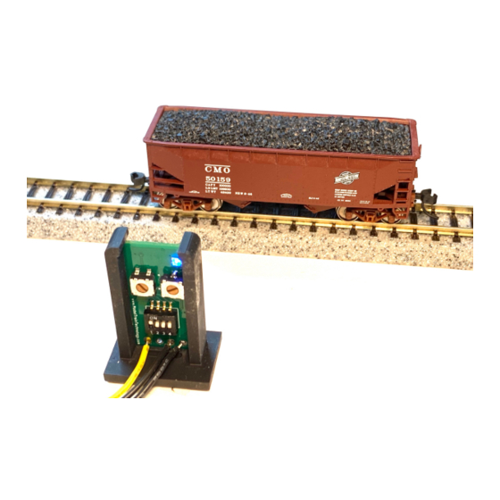
• Includes a 2mm screwdriver. Indicator LED Light Range Adjust Timeout Adjust DIP SWITCHES Yellow Signal Wire (OPEN DRAIN TO GND) 5VDC The board is powered with a 5V DC supply. To make sure all the detection works properly we designed a low cost 5V Power Center Module which also makes it easy to connect things up. - Page 5 The detector can be set to detect an adjustable Wide Range from 5mm up to 150mm – or anything smaller than that as you chose. In this first example, anything within the range you set beginning at 5mm - will trigger the detector.
- Page 6 The default setting with the trim pot adjusted all the way to the left (counterclockwise) is under 1 second. With the dial all the way to the right (clockwise) the timeout period is either 30 seconds or 60 seconds depending on the timeout DIP setting. If you are using the PRECISION DETECTOR™...
-
Page 7: Installation And Testing
On the board is a blue indicator LED. This will flash four times when power is first turned on and thereafter will light when the detector is triggered. (INVERT mode will have the light ON when not triggered and OFF when triggered) INSTALLATION and TESTING The default setting (via DIP switches) is to detect the Wide Range from 5mm to 150mm. - Page 8 Turn the timeout back all the way to the left (1 second) during the following testing and experimentation. It is easier to change the detector settings when the timeout setting is zero. It just helps speed things up to follow what’s going on instead of waiting for the time out. The MTT PRECISION DETECTOR™...
- Page 9 5. Test by moving the car in and out of the sight of the detector. The Blue indicator should go on and off. Move the car out of sight. Place you hand or an object between the detector and the track. Nothing should happen since it is not within the 10mm range that you set –...
- Page 10 Keep in mind that the trim pot rotation is 300 degrees and that allows adjustment over 145mm. When you are adjusting the range in N Scale it only takes a small amount of rotation to move 10mm. The Yellow Signal wire can now be connected to the controller device of your choice.
- Page 11 We did not supply a wire for this purpose because this is uncommon and usually not necessary, but the connection is there if you need it. By connecting the two grounds together, the YELLOW signal wire now has a path to GROUND to complete the OPEN DRAIN (to ground) circuit. INVERTED SIGNAL An INVERTED SIGNAL simply means that the PRECISION DETECTOR™...
- Page 12 INVERT switch #4 shown in the UP (ON) position TRIGGER TIMEOUT SETTINGS Rotate the trim pot (variable resistor) clockwise to increase the length of the detector timeout. There are two ranges: 0-30 and 31-60 seconds. You change to the 31-60 second range by turning DIP switch #3 ON.
- Page 13 The PRECISION DETECTOR™ – Trackside is very fast and very precise to the point that it can detect the space between cars when a train is moving slowly. To avoid the sensor going off in this situation, adjust the timeout just a little above the time that it takes a car with the biggest gap to cover the detection area.
- Page 14 April 2021...
- Page 15 On the next few pages are graphics to depict how the track detection system works and the various range distances. These guidelines from which you will need to fine tune for your particular layout, scale and train car situation. There is one option that we decided to leave intact, but it has an operating flaw –...
- Page 16 April 2021...
- Page 17 April 2021...
- Page 18 April 2021...
- Page 19 April 2021...
- Page 20 April 2021...
- Page 21 April 2021...
- Page 22 ELECTRONICS AND STATIC ELECTRICITY The MTT PRECISION DETECTOR™ - Trackside circuit board and components are exposed when the cover is off. Static electricity can cause component failure. Scuffing along a carpet and then touching one of the component connectors can cause a static spark. These components are fairly rugged –...
-
Page 23: Limitation Of Liability
ONE YEAR MANUFACTURER WARRANTY : We warrants this product to be free from defects in workmanship and materials, under normal residential use and conditions, for a period of one (1) year for the original invoice date. Shipping and handling fees are to be paid for by the customer. LIMITATION OF LIABILITY UNDER NO CIRCUMSTANCE SHALL COMPANY OR ITS AFFILIATES, PARTNERS, SUPPLIERS OR LICENSORS BE LIABLE... - Page 24 Model Train Technology LLC 10524 Moss park Rd. Ste. 204-256 Orlando, Florida 32832 407-242-5436 www.ModelTrainTechnology.com support@modeltraintechnology.com Version 1.1a Copyright© 2021 Model Train Technology LLC April 2021...
Need help?
Do you have a question about the PRECISION DETECTOR Trackside and is the answer not in the manual?
Questions and answers