Bodet BTX6015 Installation And Operation Instructions Manual
Goal indicator for ice hockey
Hide thumbs
Also See for BTX6015:
- Installation manual (36 pages) ,
- Installation and operating instructions manual (10 pages)
Advertisement
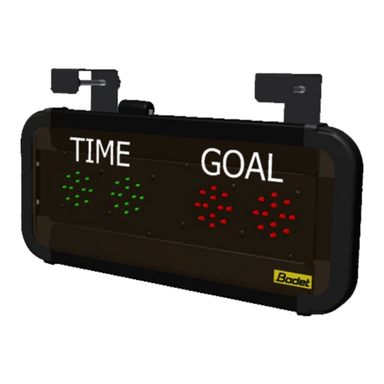
GOAL Indicator
for ice hockey
Installation and operation instructions
Upon receipt, always check the product for damage during shipment.
If any is found, you may file a damage claim with the carrier.
ZI de Martigny
37210 Parçay Meslay
Tél. 02 47 29 77 40
Fax 02 47 29 77 41
www.bodet-sport.com
Ref. 607638B
1
Advertisement
Table of Contents

Related Manuals for Bodet BTX6015


Summary of Contents for Bodet BTX6015
- Page 1 37210 Parçay Meslay Tél. 02 47 29 77 40 Fax 02 47 29 77 41 www.bodet-sport.com Ref. 607638B Upon receipt, always check the product for damage during shipment. If any is found, you may file a damage claim with the carrier.
- Page 2 - Installation ground connection as per EE or EN (earth/earth or earth/neutral) power supply diagram. - Bodet shall not be held responsible for any use not in compliance with these instructions. - Any modification to the product shall void the warranty.
- Page 3 I - Checking the supplied equipment The pack is made of the goal indicator panel + the power cord + the Start/Stop handheld push button. Goal indicator panel Handheld Start/Stop push button Power cord Note: The power cord supplies the power to the panel. The handheld Start/Stop push button turns on a GOAL Led indicator (1 indicator per impulse).
- Page 4 III - Wall mounting 1/ Install 4 x Ø6mm screws and matching plugs on the wall and slide the panel over the 4 screws. (The screws and plugs are not supplied by Bodet). IV - Clamp mounting 1/ Place the panel on its support.
- Page 5 Goal indicator panel Power cord 2/ Connect the “goal lights module” to the Bodet ice hockey main scoreboard (RS485 communication) This connection will allow the “goal lights module” to synchronise itself with the scoreboard in order to display the game clock stopped.
- Page 6 VI - Dip switches setting 1st dip bank 2nd dip bank 1st dip bank On the 1st dip bank, dips 1 to 4 are used for the factory configuration of the panel. Out of the factory the dips are set as follow: Dip 1 Dip 2 Dip 3 Dip4 on ↑ on ↑ on ↑ off ↓ Dips 5 to 7 are used to identify each panel (If several panels are used on the same site each panel must have its own number).
Need help?
Do you have a question about the BTX6015 and is the answer not in the manual?
Questions and answers