Table of Contents
Advertisement
Advertisement
Table of Contents

Related Manuals for EnGenius ENH Series


Summary of Contents for EnGenius ENH Series
- Page 1 Wireless 802.11b/g/n Mesh Router Model: OM2P-LC OM2P-HS User Manual Version : 1.0...
-
Page 2: Table Of Contents
Table of Contents CHAPTER 1 PRODUCT OVERVIEW.......................... 7 1.1 F EATURE .................................. 7 1.2 B ENEFITS .................................. 8 1.3 P ACKAGE ONTENTS .............................. 9 1.3 S YSTEM EQUIREMENT .............................. 9 CHAPTER 2 HARDWARE OVERVIEW ........................10 CHAPTER 3 INSTALLATION ............................11 CHAPTER 4 CONFIGURING YOUR COMPUTER FOR TCP/IP .................14 ... - Page 3 8.2.4 WPA-PSK Mixed ............................ 45 8.2.5 WPA................................ 46 8.2.6 WPA2 ................................ 47 8.2.7 WPA Mixed .............................. 48 8.4 W IRELESS DVANCED ETTINGS ........................... 49 8.5 W MAC F IRELESS ILTER .............................. 51 8.6 WDS L ETTINGS .............................. 52 CHAPTER 9 LAN SETUP ..............................53 9.1 IP S ETTINGS ................................ 53 ...
- Page 4 13.3 C LIENT RIDGE ............................... 83 13.4 WDS B RIDGE .............................. 83 13.5 C LIENT OUTER .............................. 84 13.6 RADIUS C ONNECTIONS ............................ 84 APPENDIX A – TROUBLESHOOTING ..........................85 A.1 P ................................. 85 ROBLEM OLVING A.2 C ............................ 86 ONTACTING ECHNICAL UPPORT APPENDIX B – SPECIFICATIONS ............................87 APPENDIX C – GLOSSARY ..............................87 ...
- Page 5 This document is written for networking professionals responsible for installing and managing the EnGenius ENH Series Outdoor Access Point/Bridge. To use this guide, you should have knowledge about TCP/IP and IEEE 802.11 standards, and be familiar with the concepts and terminology associated with wireless local-area networks (WLANs).
- Page 6 Icons used Figures in this document may use the following generic icons. EHN device WLAN signal Client computer laptop Internet Client computer desktop PoE injector Power adapter...
-
Page 7: Chapter 1 Product Overview
Chapter 1 Product Overview Thank you for choosing OM2P‐LC/OM2P‐HS. The OM2P‐LC/OM2P‐HS is a long range, high‐performance IEEE 802.11b/g/n network solution that provides Access Point, Client Bridge, WDS, and Client Router functions in a single device. In addition to providing the latest wireless technology, the OM2P‐LC/OM2P‐HS supports Power over Ethernet and Power by Adapter capabilities, which allow the device to be installed easily in nearly any indoor or outdoor location. Advanced features include power level control, narrow bandwidth selection, traffic shaping, and Real‐time RSSI indication. A variety of security features help to protect your data and privacy while you are online. Security features include Wi‐Fi Protected Access (WPA‐PSK/WPA2‐PSK), 64/128/152‐bit WEP Encryption, and IEEE 802.1x with RADIUS. 1.1 Feature The following list summarizes the key features of the OM2P-LC/OM2P-HS: ... -
Page 8: Benefits
1.2 Benefits The OM2P‐LC/OM2P‐HS is the ideal product around which you can build your WLAN. The following list summarizes a few key advantages that WLANs have over wired networks: Ideal for hard‐to‐wire environments There are many scenarios where cables cannot be used to connect networking devices. Historic and older buildings, open areas, and busy streets, for example, make wired LAN installations difficult, expensive, or impossible. Temporary workgroups WLANs make it easy to provide connectivity to temporary workgroups that will later be removed. ... -
Page 9: Package Contents
1.3 Package Contents Open the package carefully and make sure it contains all of the items listed below. ‐ One EnGenius Wireless Access Point / Client Bridge (OM2P‐LC/OM2P‐HS) If any item is missing or damaged, contact your place of purchase immediately. Keep all packing materials in case you need to return the OM2P‐LC/OM2P‐HS. The OM2P‐LC/OM2P‐ HS must be returned with its original packing materials. Use only the power adapter supplied with your OM2P‐LC/OM2P‐HS. Using a different power adapter can damage the OM2P‐LC/OM2P‐HS. 1.3 System Requirement To install the OM2P‐LC/OM2P‐HS, you need an Ethernet cable and a computer equipped with: ‐ An Ethernet interface ‐ One of the following operating systems: Microsoft Windows XP, Vista, or 7; or Linux ‐ An Internet browser that supports HTTP and JavaScript ... -
Page 10: Chapter 2 Hardware Overview
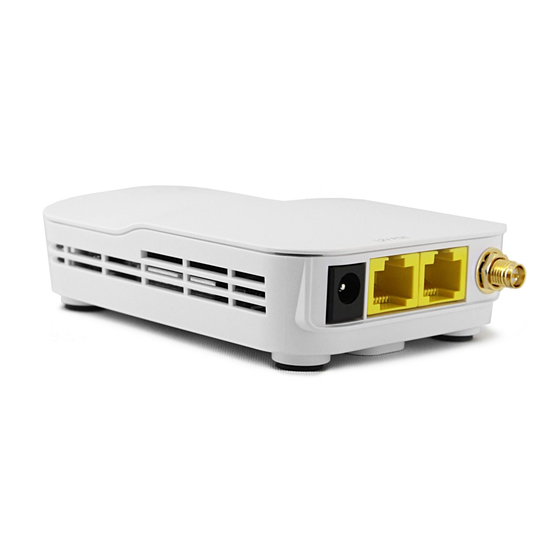
Chapter 2 Hardware Overview The following figures show the key components on the OM2P‐LC/OM2P‐HS. 2.1 Bottom V i ew The bottom panel of the OM2P‐LC/OM2P‐HS contains two RJ‐45 ports, a PoE interface, and a Reset button. A removable cover covers these components. ‐ The RJ‐45 port connects to an Ethernet adapter in a computer you use to configure the OM2P‐ LC/OM2P‐HS. For more information, see Chapter 4. ‐ The PoE interface allows the OM2P‐LC/OM2P‐HS to be powered using the supplied PoE injector. ‐ The Reset button can be used to reboot the OM2P‐LC/OM2P‐HS and return the device to its default factory configuration, erasing any overrides you may have made to the device’s default settings. The Reset button is recessed to prevent accidental resets. To reboot the OM2P‐ LC/OM2P‐HS, use a flat object such as a pencil to press the Reset button for approximately 10 seconds and then stop pressing the Reset button. 2.2 Back Panel The back panel of the OM2P‐LC/OM2P‐HS contains the LED indicators that show the link quality and status of the OM2P‐LC/OM2P‐HS. ... -
Page 11: Chapter 3 Installation
Chapter 3 Installation This chapter describes how to install the OM2P‐LC/OM2P‐HS. It also describes the OM2P‐LC/OM2P‐ HS LEDs. Only experienced installation professionals who are familiar with local building and safety codes and, wherever applicable, are licensed by the appropriate government regulatory authorities should install the OM2P‐LC/OM2P‐HS. 3.1 Pre‐installation Guidelines Select the optimal locations for the equipment using the following guidelines: he OM2P‐LC/OM2P‐HS should be mounted on a 1"‐4" pole. Its location should enable easy access to the unit and its connectors for installation and testing. The higher the placement of the antenna, the better the achievable link quality. The antenna should be installed to provide a direct, or near line of sight with the Base Station antenna. The antenna should be aligned to face the general direction of the Base Station. 3.2 Installing the OM2P‐LC/OM2P‐HS To install the OM2P‐LC/OM2P‐HS, use the following procedure to mount the device on a pole and refer to the figure below. 1. The bottom of the OM2P‐LC/OM2P‐HS is a movable cover. Grab the cover and pull it back hard to remove the cover. 2. Insert a standard Ethernet cable into the RJ‐45 port labeled MAIN LAN. 3. Slide the cover back to seal the bottom of the OM2P‐LC/OM2P‐HS. ... - Page 12 ...
- Page 13 3.2 Understanding the OM2P‐LC/OM2P‐HS LEDs The rear of the OM2P‐LC/OM2P‐HS has two groups of LEDs. One group, labeled INDICATORS, shows the status of the device. The second group, LINK QUALITY, shows the strength of the link between the OM2P‐LC/OM2P‐HS and the network. The following table describes the OM2P‐LC/OM2P‐HS LEDs. LED Color Mode Status Power Green OFF= OM2P‐LC/OM2P‐HS is not receiving power. ON= OM2P‐LC/OM2P‐HS is receiving power. LAN Green OFF = OM2P‐LC/OM2P‐HS is not connected to the network. ON = OM2P‐LC/OM2P‐HS is connected to the network, but not sending or receiving data. Blink = OM2P‐LC/OM2P‐HS is sending or receiving data. WLAN Green Access Point OFF = OM2P‐LC/OM2P‐HS radio is off and the device or Client is not sending or receiving data over the wireless LAN. Bridge Mode ON = OM2P‐LC/OM2P‐HS radio is on, and the device is not sending or receiving data over the wireless LAN. Blink = OM2P‐LC/OM2P‐HS radio is on, and the device Link Quality See Status Access Point Shows the strength of the link between the OM2P‐ LC/OM2P‐HS ...
-
Page 14: Chapter 4 Configuring Your Computer For Tcp/Ip
Chapter 4 Configuring Vour Computer for TCP/IP , To configure the OM2P-LC/OM2P-HS use a computer that is configured for TCP/IP. This chapter describes how to configure the TCP/IP settings on a computer that will be used to configure the OM2P-LC/OM2P-HS. -
Page 15: Configuring Microsoft Windows 7
4.1 Configuring Microsoft Windows 7 Use the following procedure to configure a computer running Microsoft Windows 7. 1. In the Start menu search box, type: ncpa.cpl 2. When the Network Connections List appears, right‐click the Local Area Connection icon and click Properties. 3. In the Networking tab, click either Internet Protocol Version 4 (TCP/IPv4) or Internet Protocol Version 6 (TCP/IPv6), and then click Properties. ... - Page 16 4. In the properties dialog box, click Obtain an IP address automatically to configure your computer for DHCP. ...
-
Page 17: Configuring Microsoft Windows Vista
5. Click the OK button to save your changes and close the dialog box. 6. Click the OK button again to save your changes. 4.2 Configuring Microsoft Windows V i sta Use the following procedure to configure a computer running Microsoft Windows V ista with the default interface. If you use the Classic interface, where the icons and menus resemble previous Windows versions, perform the procedure in section 4.4. 1. On the Windows taskbar, click Start, click Control Panel, and then select the Network and Internet icon. 2. Click View Networks Status and tasks and then click Management Networks Connections. 3. Right‐click the Local Area Connection icon and click Properties. 4. Click Continue. The Local Area Connection Properties dialog box appears. 5. In the Local Area Connection Properties dialog box, verify that Internet Protocol (TCP/IPv4) is checked. Then select Internet Protocol (TCP/IPv4) and click the Properties button. The Internet Protocol Version 4 Properties dialog box appears. ... - Page 18 6. In the Internet Protocol Version 4 Properties dialog box, click Obtain an IP address automatically to configure your computer for DHCP. ...
-
Page 19: Configuring Microsoft Windows Xp
4.3 Configuring Microsoft Windows XP Use the following procedure to configure a computer running Microsoft Windows XP with the default interface. If you use the Classic interface, where the icons and menus resemble previous Windows versions, perform the procedure in section 4.4. 1. On the Windows taskbar, click Start, click Control Panel, and then click Network and Internet Connections. 2. Click the Network Connections icon. 3. ... -
Page 20: Configuring Microsoft Windows 2000
5. In the Local Area Connection Properties dialog box, verify that Internet Protocol (TCP/IP) is checked. Then select Internet Protocol (TCP/IP) and click the Properties button. The Internet Protocol (TCP/IP) Properties dialog box appears. 6. In the Internet Protocol (TCP/IP) Properties dialog box, click Obtain an IP address automatically to configure your computer for DHCP. Click the OK button to save this change and close the Internet Protocol (TCP/IP) Properties dialog box. 7. Click the OK button again to save your changes. 8. Restart your computer. 4.4 Configuring Microsoft Windows 2000 Use the following procedure to configure your computer if your computer has Microsoft Windows 2000 installed. 1. On the Windows taskbar, click Start, point to Settings, and then click Control Panel. 2. In the Control Panel window, double‐click the Network and Dial‐up Connections icon. If the Ethernet adapter in your computer is installed correctly, the Local Area Connection icon appears. 3. Double‐click the Local Area Connection icon for the Ethernet adapter connected to the OM2P‐LC/OM2P‐HS. The Local Area Connection Status dialog box appears. ... - Page 21 4. In the Local Area Connection Status dialog box, click the Properties button. The Local Area Connection Properties dialog box appears. 5. In the Local Area Connection Properties dialog box, verify that Internet Protocol (TCP/IP) is checked. Then select Internet Protocol (TCP/IP) and click the Properties button. 6. Click Obtain an IP address automatically to configure your computer for DHCP. 7. Click the OK button to save this change and close the Local Area Connection Properties dialog box. 8. Click OK button again to save these new changes. 9. Restart your computer. ...
-
Page 22: Configuring An Apple Macintosh Computer
4.5 Configuring an Apple Macintosh Computer The following procedure describes how to configure TCP/IP on an Apple Macintosh running Mac OS 10.2. If your Apple Macintosh is running Mac OS 7.x or later, the steps you perform and the screens you see may differ slightly from the following. However, you should still be able to use this procedure as a guide to configuring your Apple Macintosh for TCP/IP. 1. Pull down the Apple Menu, click System Preferences, and select Network. 2. Verify that the NIC connected to the OM2P‐LC/OM2P‐HS is selected in the Show field. 3. In the Configure field on the TCP/IP tab, select Using DHCP. 4. Click Apply Now to apply your settings and close the TCP/IP dialog box. ... -
Page 23: Chapter 5 Introducing The Web Configurator
Chapter 5 Introducing the Web Configurator The OM2P‐LC/OM2P‐HS has a built‐in Web Configurator that lets you manage the unit from any location using a Web browser that supports HTTP and has JavaScript installed. 5.1 Logging in to the Web Configurator After configuring the computer for TCP/IP using the procedure appropriate for your operating system, use that computer’s Web browser to log in to the OM2P‐LC/OM2P‐HS Web Configurator. 1. Launch your Web browser. 2. In the browser address bar, type 192.168.1.1 and press the Enter key. If you changed the OM2P‐LC/OM2P‐HS LAN IP address, enter the correct IP address. 3. When the Windows Security window appears, type admin as the username in the top field and type admin as the password in the bottom field. ... - Page 24 5.2 Best Practices Perform the following procedures regularly to make the OM2P‐LC/OM2P‐HS more secure and manage the OM2P‐LC/OM2P‐HS more effectively. ‐ Change the default password. Use a password that is not easy to guess and that contains different characters, such as numbers and letters. The OM2P‐LC/OM2P‐HS username cannot be changed. For more information, see page 69. ‐ Back up the configuration and be sure you know how to restore it. Restoring an earlier working configuration can be useful if the OM2P‐LC/OM2P‐HS becomes unstable or crashes. If you forget your password, you will have to reset the OM2P‐LC/OM2P‐HS to its factory default settings and lose any customized override settings you configured. However, if you back up an earlier configuration, you will not have to completely reconfigure the OM2P‐LC/OM2P‐HS. You can simply restore your last configuration. For more information, see page 73. ...
-
Page 25: Chapter 6 Status
Chapter 6 Status The Status section on the navigation drop‐down menu contains the following options: Main Wireless Client List System Log Connection Status The following sections describe these options. 6.1 Save/Load This page lets you save and apply the settings shown under Unsaved changes list, or cancel the unsaved changes and revert to the previous settings that were in effect. -
Page 26: Main
6.2 Main Clicking the Main link under the Status drop-down menu or clicking Home at the top-right of the Web Configurator shows status information about the current operating mode. The System Information section shows general system information such as operating mode, system up time, firmware version, serial number, kernel version, and application version. -
Page 27: Wireless Client List
6.3 Wireless Client List Clicking the Wireless Client List link under the Status drop-down menu displays the list of clients associated to the OM2P-LC/OM2P-HS, along with the MAC addresses and signal strength for each client. Clicking the Refresh button updates (refreshes) the client list. -
Page 28: System Log
6.4 System Log The OM2P-LC/OM2P-HS automatically logs (records) events of possible interest in its internal memory.To view the log ged information ,click the System Log link und er the Status d rop- down menu. If there is not enough internal memory to log all event, s older events are deleted from the log. ... -
Page 29: Connection Status
6.5 Connection Status Clicking the Connection Statuslink under the Status drop-down menu displays the current The information shown includes network type , SSID ,BSSID , connection status of the networ statu, s wireless mode , cu rrent ch anne, l security , data rat, e noise leve, l and sig nal strength. Wireless ... -
Page 30: Dhcp Client Table
DHCP Client Table Clicking the DHCP Client List link under the Status drop-down menu displays the clients that are associated to the OM2P-LC/OM2P-HS through DHCP.The MAC addresses and signal strength for each client are also shown. Clicking the Refresh button updates (refreshes) the client lis t. -
Page 31: Chapter 7 System
Chapter 7 System This chapter describes how to change the OM2P‐LC/OM2P‐HS operating modes. 7.1 Changing Operating Modes The OM2P-LC/OM2P-HS supports four operating modes: Access Point Client Bridge WDS Bridge Client Router ... -
Page 32: Chapter 8 Wireless Configuration
Chapter 8 Wireless Configuration This chapter describes the OM2P-LC/OM2P-HS’s wireless settings. Please read the information in this chapter carefully. If you configure a setting improperly, it can impact performance and affect the network adversely. Before you continue, be sure you selected the appropriate operating mode (see Chapter 7). - Page 33 Wireless Mode Wireless mode supports 802.11b/g/n mixed modes. Channel HT Mode The default channel bandwidth is 40 MHz.
- Page 34 Profile Isolation Restricted Client to communicate with different VID by Selecting the radio button. Accept / Cancel Click Accept to confirm the changes or Cancel to cancel and return previous settings. Clicking Accept does not apply the changes. To apply them, use Status > Save/Load (see section 4.1).
- Page 35 SSID Specify the SSID for the current profile. VLAN ID Specify the VLAN tag for the current profile. Suppressed SSID Check this option to hide the SSID from clients.
-
Page 36: Client Bridge Mode
The following figure shows an example of an OM2P-LC/OM2P-HS communicating with an Access Point/Wireless Router, such as the EnGenius EOA7530, operating in Client Bridge Mode. The sections that follow the figure below describe how to configure your OM2P-LC/OM2P-HS for Client Bridge Mode. - Page 37 discovered Access Point to establish a connection. Prefer BSSID Enter the MAC address if known. If you select an Access Point in the Site Survey, this field is completed automatically. WDS Client Click the appropriate radio button to enable or disable WDS Client.
-
Page 38: Wds Bridge Mode
8.1.3 WDS Bridge Mode Unlike traditional bridging. WDS Bridge Mode allows you to create large wireless networks by linking several wireless access points with WDS links. WDS is normally used in large, open areas, where pulling wires is cost prohibitive, restricted or physically impossible. ... - Page 39 section 4.1). MAC Address Enter the MAC address of the Access Point to which you want to extend wireless connectivity.
-
Page 40: Client Router Mode
8.1.4 Client Router Mode In Client Router Mode, you can access the Internet wirelessly with the support of a WISP. In AP Router Mode, the OM2P-LC/OM2P-HS can access the Internet via a cable or DSL modem. In this mode, the OM2P-LC/OM2P-HS can be configured to turn off the wireless network name (SSID) broadcast, so that only stations that have the SSID can be connected. - Page 41 Prefer BSSID Enter the MAC address if known. If you select an Access Point in the Site Survey, this field is completed automatically. Wireless Security See section 10.2. Accept / Cancel Click Accept to confirm the changes or Cancel to cancel and return previous settings.
-
Page 42: Wireless Security Settings
8.2 Wireless Security Settings The Wireless Security Settings section lets you configure the EOH200’s security modes: WEP, WPA-PSK, WPA2-PSK, WPA-PSK Mixed, WPA, WPA2, and WPA Mixed. We strongly recommend you use WPA2-PSK. 8.2.1 WEP ... -
Page 43: Wpa-Psk
802.11n does not allow WEP/WPA-PSK/WPA-PSK TKIP security mode. The connection mode will drop from 802.11n to 802.11g. 8.2.2 WPA-PSK ... -
Page 44: Wpa2-Psk
8.2.3 WPA2-PSK Security Mode Select WPA2-PSK from the drop-down list to begin the configuration. Encryption Select Both, TKIP, or AES as the encryption type. •... -
Page 45: Wpa-Psk Mixed
8.2.4 WPA-PSK Mixed Security Mode Select WPA-PSK Mixed from the drop-down list to begin the configuration. Encryption Select Both, TKIP, or AES as the encryption type. • Both = uses TKIP and AES. • TKIP = automatic encryption with WPA-PSK; requires passphrase. -
Page 46: Wpa
8.2.5 WPA Security Mode Select WPA from the drop-down list to begin the configuration. Encryption Select Both, TKIP, or AES as the encryption type. -
Page 47: Wpa2
8.2.6 WPA2 Security Mode Select WPA2 from the drop-down list to begin the configuration. Encryption Select Both, TKIP, or AES as the encryption type. -
Page 48: Wpa Mixed
8.2.7 WPA Mixed Security Mode Select WPA Mixed from the drop-down list to begin the configuration. -
Page 49: Wireless Advanced Settings
8.4 Wireless Advanced Settings ... - Page 50 number of packets, but increases packet sizes. Wireless Traffic Check this option to enable wireless traffic shaping. Traffic Shaping shaping regulates the flow of packets leaving an interface to deliver improved Quality of Service. Incoming Traffic Limit Specify the wireless transmission speed used for downloading.
-
Page 51: Wireless Mac Filter
8.5 Wireless MAC Filter Wireless MAC Filters are used to allow or deny network access to wireless clients according to their MAC addresses. You can manually add a MAC address to restrict the permission to access OM2P-LC/OM2P-HS. The default setting is Disable Wireless MAC Filters. ... -
Page 52: Wds Link Settings
8.6 WDS Link Settings Using WDS Link Settings, you can create a wireless backbone link between multiple access points that are part of the same wireless network. This allows a wireless network to be expanded using multiple Access Points without the need for a wired backbone to link them, as is traditionally required. -
Page 53: Chapter 9 Lan Setup
Chapter 9 LAN Setup This chapter describes the OM2P-LC/OM2P-HS Local Area Network (LAN) settings. 9.1 IP Settings This section is only available for Non-Router Mode. IP settings lets you configure the OM2P- LC/OM2P-HS LAN port IP address. -
Page 54: Spanning Tree Settings
9.2 Spanning Tree Settings Spanning Tree Status Enable or disable the OM2P-LC/OM2P-HS Spanning Tree function. Bridge Hello Time Specify Bridge Hello Time, in seconds. -
Page 55: Chapter 10 Router Settings
Chapter 10 Router Settings This section is only available for AP Router Mode and Client Router Mode. 10.1 WAN Settings This chapter describes the OM2P-LC/OM2P-HS WAN settings. There are four types of WAN connections: Static IP DHCP... - Page 56 Internet Connection ...
- Page 57 Pinging IP addresses is a common method used by hackers to test whether the IP address is valid. Blocking pings provides some extra security from hackers. Accept / Cancel Click Accept to confirm the changes or Cancel to cancel and return previous settings.
-
Page 58: Dhcp (Dynamic Ip)
10.1.2 DHCP (Dynamic IP) Select DHCP as your WAN connection type to obtain an IP address automatically. You will need to enter account name as your hostname and, optionally, DNS information. ... - Page 59 Get Automatically Click this radio button to obtain the DNS automatically from the From ISP DHCP server. Use These DNS Servers Click the radio button to set up the Primary DNS and Secondary DNS servers manually. Discard Ping on WAN Check to Enable to recognize pings on the OM2P-LC/OM2P-HS WAN interface or Disable to block pings on the OM2P- LC/OM2P-HS WAN interface.
-
Page 60: Pppoe (Point-To-Point Protocol Over Ethernet)
10.1.3 PPPoE (Point-to-Point Protocol over Ethernet) Select Point to Point Protocol over Ethernet (PPPoE) if your ISP uses a PPPoE connection. Your ISP will provide you with a username and password. This selection is typically used for DSL services. - Page 61 setting that is too low can prevent the OM2P-LC/OM2P-HS from establishing some connections. Login Enter the Username provided by your ISP. Password Enter the Password provided by your ISP. Service Name Enter the Service Name provided by your ISP. Connect on Demand Select the radio button to specify the maximum idle time.
-
Page 62: Pptp (Point-To-Point Tunneling Protocol)
叫“。" 10.1.4 PPTP (Point-to- Po int Tunneling Pr Select PPTP as your WAN connection type if your ISP uses a Point-to-Point-Tunneling Protocol (PPTP) connection. You will need to provide the IP add res , s subnet mask , defau It 9ateway (optional ,... - Page 63 Specify the Maximum Transmit Unit size. It is recommended you accept the default setting of Auto. Otherwise, packets will be fragmented downstream if the MTU is set too high or too low, which impacts network performance. In extreme cases, an MTU setting that is too low can prevent the OM2P-LC/OM2P-HS from establishing some connections.
-
Page 64: Lan Settings (Router Mode)
10.2 LAN Settings (Router Mode) IP Address Enter the LAN port IP address. IP Subnet Mask Enter the LAN IP subnet mask. -
Page 65: Vpn Pass Through
10.3 VPN Pass Through VPN Passthrough allows a secure virtual private network (VPN) connection between two computers. Enabling the options on this page opens a VPN port and enables connections to pass through the OM2P-LC/OM2P-HS without interruption. ... -
Page 66: Port Forwarding
10.4 Port Forwarding Port forwarding can be used to open a port or range of ports to a device on your network Using port forwarding, you can set up public services on your network. When users from the Internet make certain requests on your network, the OM2P-LC/OM2P-HS can forward those requests to computers equipped to handle the requests. - Page 67 Service Name Enter a name for the port forwarding rule. Protocol Select a protocol for the application: Choices are Both, TCP, and UDP.
-
Page 68: Dmz
10.5 DMZ If you have a computer that cannot run Internet applications properly from behind the OM2P- LC/OM2P-HS, you can allow the computer to have unrestricted Internet access. Enter the IP address of that computer as a Demilitarized Zone (DMZ) host with unrestricted Internet access. Adding a client to the DMZ may expose that computer to a variety of security risks, so use this option as a last resort. -
Page 69: Chapter 11 Management Settings
Chapter 11 Management Settings The Management section lets you configure administration, management VLAN, SNMP settings, backup/restore settings, firmware upgrade, time settings, and log settings. This chapter describes these settings. 11.1 Administration Click the Administration link under the Management menu to change the user name and password used to log on to the OM2P-LC/OM2P-HS Web Configurator . - Page 70 the OM2P-LC/OM2P-HS Web Configurator. Save/Apply / Cancel Click Save/Apply to apply the changes or Cancel to return previous settings. Clicking Save/Apply changes the settings immediately. You cannot undo the action.
-
Page 71: Management Vlan
11.2 Management VLAN Click the Management VLAN link under the Management menu to assign a VLAN tag to the packets. A VLAN is a group of computers on a network whose software has been configured so that they behave as if they were on a separate Local Area Network (LAN). Computers on VLAN do not have to be physically located next to one another on the LAN ... -
Page 72: Snmp Settings
11.3 SNMP Settings Click the SNMP Settings link under the Management menu to monitor network-attached devices using the Simple Network Management Protocol (SNMP). SNMP allows messages (called “protocol data unit’s) to be sent to various parts of a network. Upon receiving these messages, SNMP-compatible devices (called agents) return data stored in their Management Information Bases. -
Page 73: Backup/Restore Settings
11.4 Backup/Restore Settings Click the Backup/Restore Setting link under the Management menu to save the OM2P- LC/OM2P-HS’s current settings in a file on your local disk or load settings onto the device from a local disk. This feature is particularly convenient administrators who have several OM2P-LC/OM2P-HS devices that need to be configured with the same settings. -
Page 74: Firmware Upgrade
11.5 Firmware Upgrade Click the Firmware Upgrade link under the Management menu to upgrade the firmware of the device. To perform this procedure, downloaded the appropriate firmware from your vendor. ... -
Page 75: Time Settings
11.6 Time Settings Click the Time Settings link under the Management menu to configure the OM2P- LC/OM2P-HS system time. You can enter the time manually or, to ensure accuracy, synchronize the OM2P- LC/OM2P-HS with Network Time Protocol (NTP) server. ... -
Page 76: Log
11.7 Log Click the Log link under the Management menu to display a list of events that are triggered on the OM2P-LC/OM2P-HS Ethernet and wireless interfaces. You can consult this log if an unknown error occurs on the system or when a report needs to be sent to the technical support department for debugging purposes. -
Page 77: Diagnostics
11.8 Diagnostics Click the Diagnostics link under the Management menu to ascertain connection quality and trace the routing table to the target. ... -
Page 78: Chapter 12 Network Configuration Examples
Chapter 12 Network Configuration Examples This chapter provides step-by-step descriptions for using the OM2P-LC/OM2P-HS’s operating modes. The Access Point Mode’s default configuration allows the OM2P-LC/OM2P-HS to act as a central unit of a WLAN or as a root device of a wired environment. Repeater mode and Mesh network mode are reserved for future configuration. -
Page 79: Client Bridge Mode
Wireless Client Step1 Select the wireless mode with which you want to associate. Use site survey to scan nearby Access Point and either select the Step2 Access Point to which you want to connect, or enter the SSID manually. Step3 Configure the VLAN ID in your wireless device if available. -
Page 80: Wds Bridge Mode
12.3 WDS Bridge Mode Use this feature to link multiple Access Points in a network. All clients associated with any Access Points can communicate with each other in an ad-hoc manner. WDS Bridge Step1 Log in to the Web Configurator with the default IP address... -
Page 81: Client Router
12.4 Client Router In Client Router Mode, the OM2P-LC/OM2P-HS’s internal DHCP server allows LANs to automatically generate an IP address to share the same Internet. Connect an Access Point/WISP wirelessly and connect to LANs using a wired connection. ... -
Page 82: Access Point Mode
13.1 Access Point Mode In Access Point Mode, OM2P-LC/OM2P-HS behaves likes a central connection for stations or clients that support IEEE 802.11b/g/n networks. Stations and client must be configured to use the same SSID and security password to associate with the OM2P-LC/OM2P-HS. The OM2P-LC/OM2P- HS supports four SSIDs at the same time for secure guest access. -
Page 83: Client Bridge Mode
13.3 Client Bridge Mode In Client Bridge Mode, the OM2P-LC/OM2P-HS behaves like a wireless client that connects to an Access Point wirelessly and allows users to surf the Internet whenever they want. In this mode, use the OM2P-LC/OM2P-HS Site Survey to scan for Access Points within range. Then configure the OM2P-LC/OM2P-HS SSID and security password accordingly to associate with the Access Point. -
Page 84: Client Router Mode
13.5 Client Router Mode In Client Router Mode, the OM2P-LC/OM2P-HS’s internal DHCP server allows a number of LANs to automatically generate IP addresses to share the same Internet. In this mode, connect an AP/WISP wirelessly and connect to LANs via a wired connection. ... -
Page 85: Appendix A - Troubleshooting
Appendix A – Troubleshooting This appendix provides problem‐solving information you may find useful in case you need to troubleshoot your OM2P‐LC/OM2P‐HS. It also includes information about contacting technical support. A.1 Problem Solving Question Answer How do I reset the OM2P‐LC/OM2P‐HS? There are two ways to reset the OM2P‐ LC/OM2P‐HS, a hardware method and a software method. Both methods return the OM2P‐LC/OM2P‐HS to its factory default configuration. To use the hardware method, open the cover on the bottom panel of the OM2P‐LC/OM2P‐ HS and find the Reset button (see section 2.1). Using a flat object such as a pencil, press the Reset button for approximately 10 seconds and then stop pressing. To use the software method, click Restore to Why do I not see traffic pass after I connect the The OM2P‐LC/OM2P‐HS uses a proprietary PoE OM2P‐LC/OM2P‐HS to a PoE switch? injector and will not work with standard 802.3af‐compliant What is the default IP address of the OM2P‐ The default IP address is 192.168.1.1 I plugged the PoE to the second Ethernet port You need to plug the Ethernet cable connect to ... -
Page 86: A.2 Contacting Technical Support
The date when you received the product A brief description about the issue and the attempts you tried to resolve it To contact EnGenius Customer Service office in the United States, please use either of the following methods: Email: Support@EnGeniustech.com ... -
Page 87: Appendix B - Specifications
Appendix C – Glossary Access Point A base station in a WLAN that act as a central transmitter and receiver of WLAN radio signals. Ad Hoc Network A short-term WLAN framework created between two or more WLAN adapters, without going through an Access Point. - Page 88 detects the collision of the two transmitted packets and discards both of them. Coverage The region within which a paging receiver can reliably receive the transmission of paging signals. Coverage Area The geographical area that can be served by a mobile communications network or system. Coverage Hole ...
- Page 89 different communication protocols, data formatting structures, languages, and/or architecture. HT mode In the 802.11n system, two new formats, called High Throughput (HT), are defined for the Physical Layer, Mixed Mode, and Green Field. If a system runs 40 HT, two adjacent 20 MHz channels are used. The larger 40 MHz bandwidth can provide better transmit quality and speed. Keys Like passwords, keys open (decrypt) and close (encrypt) messages. While many encryption algorithms are commonly known and public, the key must be kept secret. Local‐Area Network (LAN) A small data network covering a limited area, such as a building or group of buildings. Most LANs connect workstations or personal computers. LANs let many users share devices such as printers as well as data. LANs also facilitate communication through e‐mail or chat sessions. Media Access Control (MAC) Address Address associated with every hardware device on the network. Every 802.11 wireless device has its own specific MAC address. This unique identifier is hard‐coded into the device and can be used to provide security for WLANs. When a network uses a MAC table, only the 802.11 radios that have their MAC addresses added to that network's MAC table can access the network. Network Address Translation (NAT) An Internet standard that lets a LAN use one set of IP addresses for internal traffic and a second set of addresses for external traffic. Network Time Protocol (NTP) A protocol that lets devices synchronize their time with a time server. NTP uses TCP or UDP port 123 by default. Passphrase A text string that automatically generates WEP keys on wireless client adapters. Power Over Ethernet (PoE) A PoE provides power to PoE‐enabled devices using an 8‐pin CAT 5 Ethernet cable, eliminating the need for a power source. Preamble Synchronizes transmissions in a WLAN. The preamble type defines the length of the Cyclic Redundancy Check block for communication between a device and roaming wireless stations. Protected Extensible Authentication Protocol (PEAP) ...
- Page 90 management for computers to connect and use a network service. Because of its broad support and ubiquitous nature, the RADIUS protocol is often used by ISPs and enterprises to manage access to the Internet or internal networks, WLANs, and integrated e‐mail services. Service Set Identifier (SSID) Name of a WLAN. All wireless devices on a WLAN must use the same SSID to communicate with each other. Simple Network Management Protocol (SNMP) An Internet‐standard protocol for managing devices on IP networks. Snooping Passively watching a network for data, such as passwords, that can be used to benefit a hacker. Temporal Key Integrity Protocol (TKIP) An encryption protocol that uses 128‐bit keys. Keys are dynamically generated and distributed by the authentication server. TKIP regularly changes and rotates encryption keys, with an encryption key never being used twice. Transmission Control Protocol/Internet Protocol (TCP/IP) A protocol that allows communications over and between networks. TCP/IP is the basis for Internet communications. Weighted Fair Queuing (WFQ) WFQ services queues are based on priority and queue weight. Queues with larger weights get more service than queues with smaller weights. This highly efficient queuing mechanism divides available bandwidth across different traffic queues. Wired Equivalent Privacy (WEP) Security protocol that provides a WLAN with a level of security and privacy comparable to that of a wired LAN. WEP encrypts data sent between wired and WLANs to keep transmissions private. Wireless Local‐Area Network (WLAN) WLANs use RF technology to send and receive data wirelessly in a certain area. This lets users in a small zone send data and share resources such as printers without using cables to physically connect each computer. Wi‐Fi Protected Access (WPA ) A subset of the IEEE 802.11i standard. WPA applies IEEE 802.1x and Extensible Authentication Protocol (EAP) to authenticate wireless clients using an external RADIUS database. WPA uses Temporal Key Integrity Protocol (TKIP), Message Integrity Check (MIC), and IEEE 802.1x to encrypt data. See also WPA‐PSK (WPA ‐Pre‐Shared Key). Wi‐Fi MultiMedia (WMM) Part of the IEEE 802.11e QoS enhancement to the Wi‐Fi standard that ensures quality of service for multimedia applications in WLANs. ...
- Page 91 WPA2 A wireless security standard that defines stronger encryption, authentication, and key management than WPA. It includes two data encryption algorithms, Temporal Key Integrity Protocol (TKIP) and Advanced Encryption Standard (AES), in the Counter mode with Cipher block chaining Message authentication Code Protocol (CCMP). Wireless Distribution System (WDS) A technology that lets Access Points communicate with one another to extend the range of a WLAN. ...
-
Page 92: Appendix D - Fcc Interference Statement
IMPORTANT NOTE: FCC Radiation Exposure Statement: This equipment complies with FCC radiation exposure limits set forth for an uncontrolled environment. This equipment should be installed and operated with minimum distance 20cm between the radiator & your body. This transmitter must not be co‐located or operating in conjunction with any other antenna or transmitter. Copyright © 2011 ENGENIUS TECHNOLOGIES, INC., All rights reserved.
Need help?
Do you have a question about the ENH Series and is the answer not in the manual?
Questions and answers