Table of Contents
Advertisement
Quick Links
W
att
Reference Manual
WattNode Pulse
Models
WNB-3Y-208-P
WNB-3Y-400-P
WNB-3Y-480-P
WNB-3Y-600-P
WNB-3D-240-P
WNB-3D-400-P
WNB-3D-480-P
N
ode
https://ctlsys.com
P
ulse
®
WattNode Revenue Pulse
Models
RWNB-3Y-208-P
RWNB-3Y-400-P
RWNB-3Y-480-P
RWNB-3Y-600-P
RWNB-3D-240-P
RWNB-3D-400-P
RWNB-3D-480-P
Rev V18c
(M5)
Advertisement
Table of Contents

Related Manuals for CCS WattNode Revenue Pulse RWNB-3Y-208-P


Summary of Contents for CCS WattNode Revenue Pulse RWNB-3Y-208-P
- Page 1 ulse ® Reference Manual WattNode Pulse WattNode Revenue Pulse Models Models WNB-3Y-208-P RWNB-3Y-208-P WNB-3Y-400-P RWNB-3Y-400-P WNB-3Y-480-P RWNB-3Y-480-P WNB-3Y-600-P RWNB-3Y-600-P WNB-3D-240-P RWNB-3D-240-P WNB-3D-400-P RWNB-3D-400-P WNB-3D-480-P RWNB-3D-480-P Rev V18c (M5) https://ctlsys.com...
- Page 2 Information in this document is subject to change without notice. ©2007-2021 Continental Control Systems, LLC. All rights reserved. Document Number: WNB-P-V18c Revision Date: Oct 4, 2021 Continental Control Systems, LLC. +1 (303) 444-7422 Web: https://ctlsys.com WattNode is a registered trademark of Continental Control Systems, LLC. FCC Information This equipment has been tested and complies with the limits for a Class B digital device, pursu- ant to part 15 of the FCC Rules.
-
Page 3: Table Of Contents
Contents Overview ..........................4 Pulse Outputs ..........................4 Diagnostic LEDs ..........................4 Current Transformers ........................4 Additional Literature ......................... 4 Front Label ............................5 Installation ..........................7 Precautions ............................. 7 Electrical Service Types ........................8 Single-Phase Two-Wire with Neutral ..................9 Single-Phase Three-Wire (Mid-Point Neutral) ................10 Single-Phase Two-Wire without Neutral ..................11 Three-Phase Four-Wire Wye .....................12 Three-Phase Three-Wire Delta Without Neutral .................13... -
Page 4: Overview
Overview Congratulations on your purchase of the WattNode Pulse watt/watt-hour transducer/meter. ® It accurately measures energy and power in a compact package. The WattNode meter can fit in existing electric service panels avoiding the costly installation of sub-panels and associated wiring. -
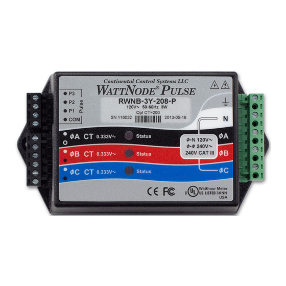
Page 5: Front Label
Front Label This section describes all the connections, information, and symbols that appear on the front label. Continental Control Systems LLC ULSE ® WNB-3Y-208-P 120V~ 50-60Hz 3W SN 59063 2010-09-26 ØA CT Status 0.333V~ ØA Ø-N 140V~ Ø-N 140V~ Ø-Ø 240V~ Ø-Ø... - Page 6 M, N, O: Current transformer (CT) inputs. These indicate CT screw terminals. Note the white and black circles at the left edge of the label: these indicate the color of the CT wire that should be inserted into the corresponding screw terminal. The terminals marked with black circles are connected together internally.
-
Page 7: Installation
Installation Precautions DANGER — HAZARDOUS VOLTAGES WARNING - These installation/servicing instructions are for use by qualified personnel only. To avoid electrical shock, do not perform any servicing other than that contained in the operating instructions unless you are qualified to do so. Always adhere to the following checklist: Only qualified personnel or licensed electricians should install the WattNode meter. -
Page 8: Electrical Service Types
Electrical Service Types Below is a list of service types, with connections and recommended models. Note: the ground connection improves measurement accuracy, but is not required for safety. Line-to- Meter Electrical Line-to- Meter Line Service Service (or Load) Types Neutral (Vac) Powered by (Vac) Type... -
Page 9: Single-Phase Two-Wire With Neutral
Single-Phase Two-Wire with Neutral This configuration is most often seen in homes and offices. The two conductors are neutral and line. For these models, the meter is powered from the N and ØA terminals. Up to three such circuits may be monitored with one meter by also using the ØB and ØC inputs. Monitoring Equip- ULSE ®... -
Page 10: Single-Phase Three-Wire (Mid-Point Neutral)
Single-Phase Three-Wire (Mid-Point Neutral) This configuration is seen in North American residential and commercial service with 240 Vac for large appliances. The three conductors are a mid-point neutral and two line voltage wires with AC waveforms 180° out of phase; this results in 120 Vac between either line conductors (phase) and neutral, and 240 Vac between the two line conductors (phases). -
Page 11: Single-Phase Two-Wire Without Neutral
Single-Phase Two-Wire without Neutral This is seen in residential and commercial service with 208 to 240 Vac for large appliances. The two conductors have AC waveforms 120° or 180° out of phase. Neutral is not used. For this configuration, the meter is powered from the ØA and ØB (phase A and phase B) terminals. For best accuracy, we recommend connecting the N (neutral) terminal to the ground terminal. -
Page 12: Three-Phase Four-Wire Wye
Three-Phase Four-Wire Wye This is typically seen in commercial and industrial environments. The conductors are neutral and three power lines with AC waveforms shifted 120° between phases. The line voltage con- ductors may be connected to the ØA, ØB, and ØC terminals in any order, so long as the CTs are connected to matching phases. -
Page 13: Three-Phase Three-Wire Delta Without Neutral
Three-Phase Three-Wire Delta Without Neutral This is typically seen in manufacturing and industrial environments. There is no neutral wire, just three power lines with AC waveforms shifted 120° between the successive phases. With this configuration, the line voltage wires may be connected to the ØA, ØB, and ØC terminals in any order, so long as the CTs are connected to matching phases. -
Page 14: Mounting
The WattNode meter will correctly measure services with a grounded leg, but the measured power for the grounded phase will be zero and the status LED will not light for whichever phase is grounded, because the voltage is near zero. For optimum accuracy with a grounded leg, you should also connect the N (neutral) terminal on the meter to the ground terminal;... -
Page 15: Selecting Current Transformers
Selecting Current Transformers The rated full-scale current of the CTs should normally be chosen somewhat above the maximum current of the circuit being measured (see Current Crest Factor below for more details). In some cases, you might select CTs with a lower rated current to optimize accuracy at lower current readings. -
Page 16: Connecting Current Transformers
140% 120% 100% Crest Factor Figure 8: Maximum CT Current vs. Crest Factor You may not know the crest factor for your load. In this case, it’s generally safe to assume the crest factor will fall in the 1.4 to 2.5 range and select CTs with a rated current roughly 150% of the expected RMS current. -
Page 17: Circuit Protection
● The line voltage connections should be made with wire rated for use in a service panel or junction box with a voltage rating sufficient for the highest voltage present. CCS recommends 14 or 12 AWG (1.5 mm or 2.5 mm... -
Page 18: Connecting Voltage Terminals
Connecting Voltage Terminals Always turn off or disconnect power before connecting the voltage inputs to the meter. Con- nect each phase voltage to the appropriate input on the green terminal block; also connect ground and neutral (if required). The voltage inputs to the meter do not need to be powered from to the same branch circuit as the load being monitored. -
Page 19: Output Assignments
● When wiring over long distances, use shielded twisted-pair cable to prevent interference. The pulse output channels are the collector and emitter of an optoisolator transistor (also called a photocoupler) controlled by the meter’s pulse stream (see Option SSR Outputs (p. 34) for solid-state relay outputs). -
Page 20: Pull-Up Resistor Selection
Pull-Up Resistor Selection For standard WattNode meters with the normal 4.00 Hz full-scale frequency, pull-up resistor values between 10kΩ and 100kΩ work well. You may use values of 1.0MΩ or higher to reduce power consumption for battery powered equipment. Note: pull-up resistor values of 1.0MΩ or higher will make the pulse output signal more susceptible to interference, so you may want to keep the wiring short, use shielded cable, and avoid running the pulse signal near AC wiring. -
Page 21: Installation Led Diagnostics
Installation LED Diagnostics The WattNode meter includes multi-color power diagnostic LEDs for each phase to help verify correct operation and diagnose incorrect wiring. The LEDs are marked “Status” on the label. The following diagrams and descriptions explain the various LED patterns and their meanings. The A, B, and C on the left side indicate the phase of the LEDs. - Page 22 Note: if all three LEDs are flashing red and they always turn on and off together, like the diagram for Low Line Voltage below, then the meter is experiencing an error or low line voltage, not nega- tive power. Erratic Flashing If the LEDs are flashing slowly and erratically, sometimes Green green, sometimes red, this generally indicates one of the...
-
Page 23: Measurement Troubleshooting
Bad Line Frequency Yellow If the meter detects a power line frequency below 45 Hz Yellow or above 70 Hz, it will light all the LEDs yellow for at least three seconds. The LEDs will stay yellow until the line Yellow frequency returns to normal. During this time, the meter 3.0sec should continue to accurately measure power. - Page 24 Check the specifications of your monitoring device or contact CCS support for assistance. ● The CTs are not installed on the correct line phases. Verify that the CT phasing matches the line Vac inputs.
-
Page 25: Operating Instructions
Operating Instructions Pulse Outputs The WattNode meter generates pulse outputs using one or more optoisolators (also called photocouplers). These provide 5000 Vac of isolation using an LED and a photo-transistor. This allows the meter to be interfaced to monitoring or data logging hardware without concerns about interference, ground loops, shock hazard, etc. -
Page 26: Power And Energy Computation
4.6110 CtAmps CtAmps CtAmps CtAmps 40,000 20,870 17,329 13,833 20.87 17.329 13.833 CtAmps CtAmps CtAmps CtAmps Table 5: Scale Factors - Bidirectional Outputs Contact CCS for scale factors for models with full-scale pulse output frequencies other than 4.00 Operating Instructions... - Page 27 Scale Factors - Option P3: Per-Phase Outputs The following table provides scale factors for Option P3 models with a full-scale pulse output frequencies of 4.00 Hz for each phase. Note: with Option P3, different phases can use different CTs with different rated currents. WARNING: Only use this table if you have Option P3 (Per-Phase Outputs)! Watt-hours per pulse (WHpP) Pulses Per kilowatt-hour (PpKWH)
-
Page 28: Power And Energy Equations
Using the “Pulses Per kilowatt-hour” PpKWH value from the table above for your model and current transformer, you can compute energy and power as follows (multiply by 1000 to convert kilowatts to watts): Energy (kilowatt-hours) = PulseCount / PpKWH Power (kilowatts) = 3600 PulseFreq / PpKWH •... - Page 29 Watt-Hours per Pulse PpPO • NVac • CtAmps WHpP = FSHz • 3600 Watt-Hours per Pulse per CT Rated Amp There is an alternate way of computing the energy reported by a meter using the variable WHpPpA (watt-hours per pulse per CT rated amp). If you multiply the WHpPpA by the amp rating of your CTs, the result will be the watt-hours measured each time the meter generates a pulse.
-
Page 30: Maintenance And Repair
The WattNode meter is not user serviceable. In the event of any failure, the meter must be returned for service (contact CCS for an RMA). In the case of a new installation, follow the diag- nostic and troubleshooting instructions before returning the meter for service, to ensure that the problem is not connection related. -
Page 31: Specifications
Specifications Models Nominal Vac Nominal Vac Model Phases Wires Line-to-Neutral Line-to-Line WNB-3Y-208-P 208–240 WNB-3Y-400-P WNB-3Y-480-P WNB-3Y-600-P WNB-3D-240-P 120* 208–240 3–4 WNB-3D-400-P 230* 3–4 WNB-3D-480-P 277* 3–4 * Note: the delta models have an optional neutral connection that may be used for measuring wye circuits. -
Page 32: Accuracy
● Option PW: Pulse Width - This specifies the pulse ON (closed or conducting) period in milliseconds. For example, Opt PW=100 configures 100 millisecond pulse ON periods. See Manual Supplement MS-17: Option PW (Pulse Width) for details. ● Option Kh: Watt‑hour Constant - This specifies the watt-hour constant, or the number of watt-hours that must accumulate for each pulse generated by the meter. -
Page 33: Measurement
Note: Option PV WattNode models may not meet these accuracy specifications for the P3 output channel when measuring a two-phase inverter or multiple inverters. Measurement Creep Limit: 0.10% (1/1000th) of full-scale. Whenever the real power for a phase drops below the creep limit, the output power (real) for the phase will be forced to zero. -
Page 34: Electrical
Saturation Voltage vs. Load Current: this is the typical voltage (at room temperature) mea- sured between the COM terminal and P1, P2, or P3 when the optoisolator is on (conduct- ing). Ideally, this voltage would be zero, but instead, it varies with the load current. 1000 0.01 Optoisolator Current (mA) - Page 35 Real Real Power Power Power Rated Model Power Power Supply Supply Factor (60 Hz) (50 Hz) Range (Vac) Terminals WNB-3Y-208-P 1.6 W 1.8 W 0.75 4 VA 96 – 138 N and ØA WNB-3Y-400-P 1.6 W 1.8 W 0.64 4 VA 184 –...
-
Page 36: Certifications
Certifications Safety: UL 61010-1 (E312220); CAN/CSA-C22.2 No. 61010-1-04; IEC 61010-1 Immunity: EN 61326: 2002 (Industrial Locations) Electrostatic Discharge: EN 61000-4-2: 4 kV contact, 8 kV air: (B) Self-Recovering Radiated RF Immunity: EN 61000-4-3: 10 V/m: (A) No Degradation Electrical Fast Transient / Burst: EN 61000-4-4: 2 kV: (B) Self-Recovering Surge Immunity: EN 61000-4-5: 1 kV I/O, 4 kV AC: (B) Self-Recovering Conducted RF Immunity: EN 61000-4-6: 3 V: (A) No Degradation Voltage Dips, Interrupts: EN 61000-4-11: (B) Self-Recovering... - Page 37 Common CT Specifications Type: voltage output, integral burden resistor Output Voltage at Rated Current: 0.33333 Vac (one-third volt) Standard CT Wire Length: 2.4 m (8 feet) Optional CT Wire Length: up to 30 m (100 feet) Split-Core CTs Also called “opening” current transformers. Any UL Listed CT with a 0.333 Vac output may be used as well as the following UL Recognized CTs under UL file numbers E96927 or E325972: CTM-0360-xxx, ACT-0750-xxx, CTS-0750-xxx, CTS-1250-xxx, CTS-2000- xxx, and CTL-1250-xxx where xxx indicates the full scale current rating.
-
Page 38: Warranty
Customer acknowledges that CCS’s aggregate liability to Customer relating to or arising out of the sale or use of CCS’s products, whether such liability is asserted on the basis of contract, tort or otherwise, shall not exceed the purchase price paid by Customer for the products in respect of which damages are claimed.
Need help?
Do you have a question about the WattNode Revenue Pulse RWNB-3Y-208-P and is the answer not in the manual?
Questions and answers