
Subscribe to Our Youtube Channel
Related Manuals for CCS WattNode Pulse Output


Summary of Contents for CCS WattNode Pulse Output
- Page 1 ® Pulse Output Installation and Operation Manual Continental Control Systems http://www.ccontrolsys.com Rev 1.20eUL...
- Page 2 Information in this document is subject to change without notice. No part of this document may be reproduced or transmitted in any form or by any means, electronic or mechanical without the prior written permission of Continental Control Systems, LLC. ©2007 Continental Control Systems, LLC.
-
Page 3: Table Of Contents
Contents OVERVIEW......................... 2 WattNode ..............................2 Current Transformers..........................2 Optoisolator Output ............................ 2 INSTALLATION......................2 Precautions..............................3 Measurement Configurations........................3 Single-Phase Two-Wire ........................4 Single-Phase Three-Wire ........................5 Three-Phase Four-Wire Wye........................ 6 Three-Phase Three-Wire Delta......................7 Mounting..............................8 Current Transformers..........................9 Approved Current Transformers ...................... -
Page 4: Overview
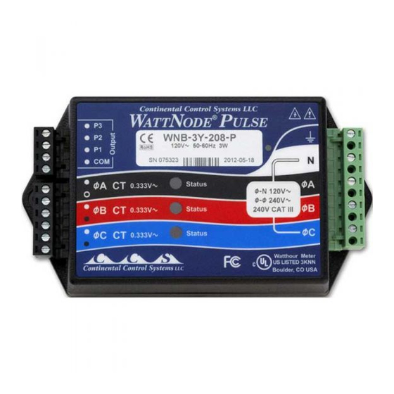
Overview WattNode ® Congratulations on your purchase of the WattNode , the most compact instrumentation-grade watt/watt- hour transducer available. Using state-of-the-art ASIC and surface mount components, the WattNode offers precision energy and power measurements in a compact package. The WattNode enables you to make precise power and energy measurements from within existing electric service panels avoiding the costly installation of subpanels and associated wiring. -
Page 5: Precautions
Always adhere to the following checklist: 1) CCS recommends that a licensed electrician install the WattNode. 2) CCS recommends that the WattNode be installed either in an electrical enclosure (panel or junction box) or in a limited access electrical room. -
Page 6: Single-Phase Two-Wire
Single-Phase Two-Wire The single-phase two-wire 120 VAC configuration is most often seen in homes and offices. The two wires are neutral and line. Any unused CT inputs must be shorted with an insulated jumper wire. Single-phase two-wire circuits should be measured with models WNA-1P-240-P or WNA-3Y-208-P. If you wish to measure a single phase two wire 220 to 240 VAC circuit, use the WNA-3Y-400-P and connect the two wires to the neutral and phase A terminals. -
Page 7: Single-Phase Three-Wire
Single-Phase Three-Wire This is seen in residential and commercial service with 240 VAC for large appliances. The three wires are neutral and two line voltage wires with AC waveforms 180° out of phase. This results in 120 VAC between either line wire and neutral, and 240 VAC (or sometimes 208 VAC) between the two line wires. Any unused CT inputs must be shorted with an insulated jumper wire. -
Page 8: Three-Phase Four-Wire Wye
Three-Phase Four-Wire Wye This is typically seen in commercial and industrial environments. The wires are neutral and three power lines with AC waveforms shifted 120° between the successive phases. With this configuration, the line voltage wires may be connected to the phase A, B and C terminals in any order, so long as the CTs are connected to matching phases. -
Page 9: Three-Phase Three-Wire Delta
Three-Phase Three-Wire Delta WARNING This configuration is dangerous because there is no neutral wire, and as a result the screw terminals to connect the CTs will have line voltages on them whenever the WattNode is powered. Therefore, for safety, it is critical that the WattNode is not powered while connecting the CTs. -
Page 10: Mounting
Mounting Mount the WattNode so that it is protected from moisture, direct sunlight and high temperatures. Due to its exposed screw terminals, the WattNode should always be installed in an electrical service panel, a junction box, or an electrical closet. The WattNode may be installed in any position. The WattNode has two 7/32"... -
Page 11: Current Transformers
The WattNode should only be used with the following UL recognized current transformers, which are available from Continental Control Systems. Using non-approved transformers will invalidate the WattNode’s UL listing. Manufacturer: Magnelab Corporation UL File Number: E96927 Approved Models: CCS Model Number Magnelabs Part # Rated Amps Opening Diameter CTS-0750-xxx SCT-0750-xxx 5 –... -
Page 12: Connecting Voltage Terminals
There are two steps to connecting the current transformers: pass the wire to be measured through the CT and connect the CT to the WattNode. Note: always remove power before disconnecting any live wires. Split-core CTs may be mounted around a wire by opening one side of the CT, sliding the CT around the wire, and then closing the open side of the CT. -
Page 13: Connecting Output
When connecting the WattNode, do not place more than one voltage wire in a screw terminal; use separate wire nuts or terminal blocks if needed. The screw terminals handle wire up to 12 AWG. Prepare the voltage wires by stripping the wires to expose 1/4" (6 mm) of bare wire. Do not leave more than 5/16" (8 mm) or less than 3/16"... -
Page 14: Installation Summary
The output is completely isolated from all dangerous voltages, so it can be connected at any time. For short distances (less than 2 meters), any pair of insulated wires are suitable for connection to the monitoring equipment. For longer distances, a shielded twisted-pair cable is recommended to prevent interference. Since the output wiring will be in the same location as line voltage wiring, it is recommended that the output wiring have a 600V rating. -
Page 15: Installation Troubleshooting
Installation Troubleshooting SYMPTOM: The WattNode is reporting zero power. Probable Causes Corrective Actions First, make sure that the light gray voltage connector is firmly The WattNode is not receiving the line voltage that it needs. seated. Then, using a voltmeter, perform the following checks. For 1P and 3Y models measure the voltage between the NEUTRAL and øA terminals, for 3D models measure the voltage between the øA and øB terminals. - Page 16 The voltage and CT wires may be wired The best approach is to visually verify that everything is wired out of phase. correctly, but if that is not a feasible option, then follow PROCEDURE B below. The WattNode is not functioning If another WattNode with the same model number is installed correctly.
-
Page 17: Operating Instructions
Operating Instructions Power and Energy Computation The power is a function of the pulse frequency, while the energy is a function of the count of pulses. The variable nCTs is the maximum number of CTs that the WattNode model can use. The variable CTAmps is the full-scale current rating of the CTs. -
Page 18: Scale Factors
Scale Factors Pulses Per kilowatt-hour Watt-hours per pulse CT Size 1P-240 3D-240 1P-240 3D-240 3Y-480 3D-480 3Y-600 3Y-480 3D-480 3Y-600 (amps) 3Y-208 3Y-400 3Y-208 3Y-400 8000.00 4000.00 3465.70 2000.00 2766.571 0.125 0.250 0.289 0.500 0.361 2666.67 1333.33 1155.24 666.667 922.190 0.375 0.750 0.866... -
Page 19: Accuracy
Model I.D. Rated Amps Max. Amps CTS-0750-yyy 0.75" 5, 15, 20, 30, 50, 70, 100, 150 CTS-1250-yyy 1.25" 70, 100, 150, 200, 250, 300, 400, 600 CTS-2000-yyy 2.00" 600, 800, 1000, 1200, 1500 2000 Table 6: Split-core CTs Model I.D. Rated Amps Max. -
Page 20: Warranty
CCS’s responsibility is limited to repair, replacement, or refund, any of which may be selected by CCS at its sole discretion. CCS reserves the right to substitute functionally equivalent new or serviceable used parts.
Need help?
Do you have a question about the WattNode Pulse Output and is the answer not in the manual?
Questions and answers