
Related Manuals for AUBO I Series


Summary of Contents for AUBO I Series
- Page 1 USER MANUAL AUBO-i3 & CB4 Please read this manual carefully before using the product.
- Page 3 AUBO-i3 & CB4 Translate Version 4.5 Published by AUBO (Beijing) Robotics Technology Co, Ltd. This manual is applicable to AUBORPE V 4.5. For details, please refer to the version information section of this manual. Please check the actual product version information carefully before use to...
- Page 4 The information in this manual is subject to change without notice and should not be regarded as a commitment by AUBO (Beijing) Robotics Technology Co., Ltd. AUBO (Beijing) Robotics Technology Co., Ltd. assumes no responsibility for any errors or omissions in this document. AUBO (Beijing) Robotics Technology Co., Ltd. assumes no responsibility for incidental or consequential damages arising from use of this manual and products described herein.
-
Page 5: Table Of Contents
V4.5 CATALOG CATALOG ..........................I PREFACE ..........................VII COMPONENTS OF AUBO-I3 ROBOT ................VIII MORE INFORMATION ....................VIII 1. SAFETY ..........................9 Introduction ........................9 Warning Symbols in this Manual .................. 9 Safety Precautions ....................... 10 General ......................10 Terms and Conditions ..................10 Operator safety .................... - Page 6 End-effector Installation ..................... 35 Mechanical structure size of end-effector flange ..........35 Cable connection ......................35 7. THE I SERIES STANDARD CONTROL BOX ............39 Introduction ......................... 39 Electrical warnings and cautions ................40 Control box panel introduction ................... 40 Control box front panel ..................
- Page 7 7 Step Mode Control ......................91 8 Position control ........................91 9 Coordinate system ......................93 9 User-defined coordinate system ..................93 10 Robot real-time status parameter display ................. 94 11 Target selection ........................ 94 12 Orientation Control ......................94 ©2015-2019 AUBO.All rights reserved.
- Page 8 Project Tab ......................124 New Project ....................124 Load Project ....................126 Save Project ....................127 Default Project ....................128 Automove tab ....................129 Procedure ...................... 130 Procedure (process) ....................131 Calling Subproject Commands(Procedure) ..........131 ©2015-2019 AUBO.All rights reserved.
- Page 9 A GLOSSARY .......................... I B CERTIFICATION ....................... II C STOPPING TIME & STOPPING DISTANCE .............. IV D GUIDELINE ........................V E TECHNICAL SPECIFICATION ..................VI F PAYLOAD ......................... VII G ALARM INFORMATION & DESCRIPTION OF GENERAL PROBLEM ... VIII ©2015-2019 AUBO.All rights reserved.
- Page 10 V4.5 ©2015-2019 AUBO.All rights reserved.
-
Page 11: Preface
AUBO (Beijing) Robotics Technology Co., Ltd. AUBO-i3 AUBO series robot adopts the fully modular design and uses system towards developers. Users can develop their own robot control system based on the application interaface provide by the AUBO platform. Meanwhile, AUBO robot is equipped with a dedicated programmable operation interface, which allows the user to observe robot’s... -
Page 12: Components Of Aubo-I3 Robot
V4.5 Components of AUBO-i3 Robot The components of the AUBO-i3 robot are listed as below. Name Quantity Manipulator AUBO-i3 Teach Pendant Control Box Teach Pendant cable Manipulator cable Power cable Manipulator base(optional) Product outline structure is shown in picture above. -
Page 13: Safety
This indicates a potentially hazardous hot surface which, if touched, could result in injury. This indicates an imminently hazardous situation which, if not avoided, could result in injury or major damage to the equipment. ©2015-2019 AUBO.All rights reserved. -
Page 14: Safety Precautions
The following basic information needs to be understood and followed when using the robot or robot system for the first time. Also, other safety-related information will be introduced in other parts of this manual. However, it may not cover everything. In practical applications, it is necessary to analyze specific issues. ©2015-2019 AUBO.All rights reserved. - Page 15 This function is a particularly for the safety of cooperative work, but robot system must be in the normal operating range and use the AUBO series control box. If the user develops the controller personally, the robot will not have the functions above, and all the dangerous consequences are undertaken by its owner.
- Page 16 The robots authorize restructuring need in accordance with the latest version of all relevant service manuals. If the robot is changed or altered in any way, AUBO (Beijing) Robotics Technology Co., Ltd disclaims all liability. 11. User needs to check the insulation and protection measures before transportation.
- Page 17 2. AUBO (Beijing) Robotics Technology Co., Ltd cannot be held responsible for any damages caused to the robot or to other equipment due to programming errors or malfunctioning of the robot.
-
Page 18: Operator Safety
1. Each operator who uses the robotic system should be trained through a training course hosted by AUBO (Beijing) Robotics Technology Co., Ltd. Users need to make sure to fully grasp the safe and standardized operating procedures with the robot operating qualifications. Please inquire for training details, mail service@aubo-robotics.com... -
Page 19: Responsibility And Standard
V4.5 Responsibility and standard AUBO-i3 can be combined with other equipments to form a complete machine, and itself is not complete. The information in this manual does not cover how to design, install and operate a complete robot, nor does it cover all peripheral equipments that can influence the safety of the complete system. - Page 20 V4.5 AUBO (Beijing) Robotics Technology Co., Ltd seeks to ensure the accuracy and reliability of the contents in this manual but is not responsible for any errors or omissions. ©2015-2019 AUBO.All rights reserved.
-
Page 21: Hazard Identification
Integrators should be aware that specific robotic equipment may have other dangers. Combine the inherent safety design which applied by AUBO robot with the safety specifications or risk assessment performed by integrators and users, risks that are associated with AUBO-i3 collaborative operation should be lower to reasonable and practicable level. -
Page 22: Intended Use
V4.5 Intended use AUBO robot is industrial only and intended for operating or fixing tools or device or for processing or transferring components or products. AUBO robot can only be used under specified conditions. For details about the operating environment and conditions, see appendix. -
Page 23: Emergency Situations
Emergency stop buttons should comply with IEC 60947-5-5. Emergency stop button can be found on the teach pendant and the control box of AUBO-i3. The button must be pressed when a dangerous situation or emergency occurs. As shown in Figure1.1, control box is equipped with an external port for emergency stop button. -
Page 24: Recovering From The Emergency Condition
This function can reduce the damage when operators or other objects collide with manipulator. This function can reduce the collision damage and required to perform risk assessment if other use is needed. ©2015-2019 AUBO.All rights reserved. -
Page 25: Transportation And Precautions
Make sure not to overload the robot’s back or other body parts when the equipment is lifted. All regional and national guidelines should be followed. AUBO (Beijing) Robotics Technology Co., Ltd is not responsible for any damage caused during the transportation of equipment. - Page 26 V4.5 ©2015-2019 AUBO.All rights reserved.
-
Page 27: Maintenance, Repair And Disposal
Maintenance, calibration and repair work must be performed in accordance with the latest versions of Service Manuals, which can be found on the support website www.aubo-robotics.com All dealers in AUBO (Beijing) Robotics Technology Co., Ltd. should have the access to this website. -
Page 28: Disposal
4. There is no self-serviceable part in control box. If maintaining or repairing service is required, please contact your dealer or AUBO (Beijing) Robotics Technology Co., Ltd. Disposal AUBO robot must be disposed in accordance with the applicable national laws, regulations and, standards. ©2015-2019 AUBO.All rights reserved. -
Page 29: Warranties
Damage caused by accident or crash. Not installing the original assembled components and accessories. 10. The damage caused by the third-party which is not AUBO (Beijing) Robotics Technology Co., Ltd. or the designated integrator while reconstructing, adjusting or repairing the original components. - Page 30 In addition, AUBO (Beijing) Robotics Technology Co., Ltd. is not responsible for any indirect damage and consequences caused by the relevant products.
-
Page 31: Robot Hardware Composition
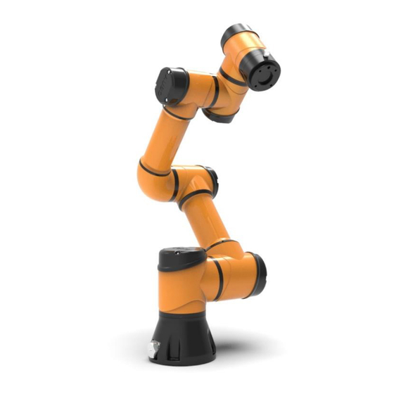
Figure 5-1 AUBO-i3 robot As shown in figure 5.1, The AUBO-i3 robot system consist of a manipulator, a control box(which can choose a variety of models), a manipulator base and a teach pendant. The manipulator imitates human which has six joints and each joint represents a degree of freedom. - Page 32 V4.5 Figure 5-2 -1 Manipualtor Joints Control box is the main control part of AUBO-i3 robot. Please read chapter 8 for any modules inside control box. AUBO-i3 provides multiple I/O interfaces, there are 4-channel digital I/O and 2-channel analog inputs on end-effector flange.
-
Page 33: Robot Installation
V4.5 6. ROBOT INSTALLATION Brief installation steps The installation of AUBO robots includes: 1. Define a robot workspace; 2. Install the robot manipulator on base; 3. Install end-effector Important safety instructions Installation Conditions: •No corrosive gases or liquids •No oil mist •No salt... -
Page 34: Workspace Of The Robot
V4.5 Install additional equipment: If any additional modules, like cable, which are not provided by AUBO (Beijing) Robotics Technology Co., Ltd., are integrated in industrial robot, users have the responsibility to ensure these modules won’t affect safety function. Safety assessment must be performed each time the robot is installed, and the instructions in Section 1 (Safety) are strictly observed. -
Page 35: Effective Working Range
V4.5 Figure 6-1 AUBO-i3 mechanical dimensions, unit: mm Effective working range The workspace of the manipulator, as shownin Figure 6.2, is a sphere of radius 625mm except the cylindrical space directly above and directly below the robot base. When choosing the installation position, be sure to consider the cylindrical space directly above and directly below the robot base must to avoid moving the tool into this cylindrical space as much as possible. -
Page 36: Hardware Installation
Hardware Installation The Manipulator Base AUBO robot manipulator base is shown in figure 6.3. There are 4 anchor bolts and 4 universal wheels for fixing and moving the robot easily. When fixing the robot, rotate the upper part of thefoundation bolt and lower it. When moving the robot, use tool (wrench) to rotate the lower part of anchor bolt and raised the bolts to make the universal wheels touch the ground. -
Page 37: Manipulator Installation
Figure 6-6 : Mounting whole size of the manipulator base. If installation method is changed (such as choosing hoisting, wall-mounted etc.), after running the AUBOPE and click the “ON” ->” OFF”, then the teach pendant will pop up following window: ©2015-2019 AUBO.All rights reserved. - Page 38 IP67 protection class. Tipping hazard. If the robot is not safely placed on a soild surface, the robot can fall over and cause injury. ©2015-2019 AUBO.All rights reserved.
-
Page 39: End-Effector Installation
There are 3 sockets on the bottom of the control box. There is a socket on the bottom of the robot body. There is a socket on the lower right side of the teach pendant. Insert the corresponding cable into the socket before use. Table 3 Cable Connection Diagram Classification Photo ©2015-2019 AUBO.All rights reserved. - Page 40 V4.5 Teach pendant cable Manipulator cable Control box power cable Socket at the bottom of the control box that is connected to the cable ©2015-2019 AUBO.All rights reserved.
- Page 41 Pay attention to the direction of insertion and tighten the locking ring after inserting it. ©2015-2019 AUBO.All rights reserved.
- Page 42 2. Make sure that all cables are properly connected before the control box is energized. Always use the original power cord correctly. 3. Never disconnect the robot cable while the robot arm is open. 4. Do not extend or modify the original cable. ©2015-2019 AUBO.All rights reserved.
-
Page 43: The I Series Standard Control Box
7. THE I SERIES STANDARD CONTROL BOX Introduction Control box is the control center of AUBO robot, which contains a control board, a safety control board, a switching power supply and a safety protection device. The control box is powered by 100V-240V AC. Its 2 internal switching power supplies convert 100V-240V AC into 12V, 24V and 48V DC which supply power for the load inside control box and the robot. -
Page 44: Electrical Warnings And Cautions
Do not touch the fastening screws and other metal parts directly by hand. Do not remove the wiring by power. Control box panel introduction The front panel, side panel and back panel of the control box are related to switches, buttons, indicators and electrical interfaces. ©2015-2019 AUBO.All rights reserved. -
Page 45: Control Box Front Panel
POWER The indicator light indicates that the robot is in an emergency EMERGENCY STOP stop state. MODE Robot manual mode and linkage mode selection. When the MANUAL/LINKAGE button is pressed, the robot enters the linkage mode. ©2015-2019 AUBO.All rights reserved. -
Page 46: Control Box Side Panel
The USB interface is provided on the right side of the control box. Users can open the control box side door by rotating the key to use this interface. Shield protection USB interfacce Figure 7-3 USB communication interface on the side of the control box ©2015-2019 AUBO.All rights reserved. - Page 47 V4.5 Figure 7-4 Control box side panel parts marking a Figure 7-5 Control box side panel parts marking b ©2015-2019 AUBO.All rights reserved.
- Page 48 48V DC power supply Motherboard (displayed after removing the shield cover) VGA differential board (displayed after removing the shield cover) Main control interface board (can be displayed after removing the shield protection cover) User IO board ©2015-2019 AUBO.All rights reserved.
-
Page 49: Control Box Back Panel
Can be used to update software, import and export project files. Electrical interface Provide external I/O interface outside the control box Teacher cable interface Connect the teach pendant cable Robot body cable Connect the robot body cable interface Power interface Connect the power cord ©2015-2019 AUBO.All rights reserved. -
Page 50: Selection Of Working Mode
The robot system has two working modes, manual and linkage, which are selected by button switches. When changing the working mode of the robot system, it is necessary to select the specified working mode after power off, and then re-inspire the teaching device and the robot body. ©2015-2019 AUBO.All rights reserved. -
Page 51: Manual Mode
The case below demonstrates how to use external device to manuplate the robot under linkage mode. Users can refer the process described below: For the first-time use, the user needs to configure the default boot program in the teach pedant manually. Instructions are below: ©2015-2019 AUBO.All rights reserved. - Page 52 Figure 7-9 linkage mode wire connection showcase Press the button “MODE MANUAL/LINKAGE” on the front panel of the control box. Power the control box. Configure the external devices singals. Then the user can follow the process below to use linkage mode. ©2015-2019 AUBO.All rights reserved.
- Page 53 Under linkage mode, if the teach pendant is not needed, after setup the default program successfully, the user can switch off the teach pendant enable in the control box. After “TEACH PENDANT ENABLE” is out, it is ok to remove the wire from the teach pendant. ©2015-2019 AUBO.All rights reserved.
- Page 54 V4.5 ©2015-2019 AUBO.All rights reserved.
-
Page 55: Internal Electrical Interface
IO Specification All AUBO robot IOs are set to NPN mode, which means low voltage level effective. When an User IO is set to “Effective” or “High” on the teach pendant, the actual voltage level at the IO output is low. -
Page 56: Control Box Communication Interface
30m, unless extended tests are performed. Control box communication interface The AUBO Robotic I Series standard control box provides a variety of electrical interfaces for connecting external devices that are easily accessible to the user. -
Page 57: Control Box I/O Power Supply
If the user needs to use external power supply, please use the following wiring method. Figure 8-3 external power supply schematic When the electrical interface of the control box is wired, the control box must be powered off. ©2015-2019 AUBO.All rights reserved. -
Page 58: Safety I/O
Reduced Mode Input 100ms 1200ms —— Safeguard Stop Reset 100ms 1200ms —— Enabling Device 100ms 1200ms —— Operational Mode 100ms 1200ms Teach Pendant Emergency Stop 100ms 1200ms 1300ms —— System Stop Input 100ms 1200ms Safety-related electrical outputs ©2015-2019 AUBO.All rights reserved. -
Page 59: Default Safety Configuration
Robot Not Stopping 1000ms SYSTEM ERROR 1000ms Default Safety Configuration The robot is shipped with a default configuration as below. In this case, the robot can be operated without any additional safety equipments Figure 8-4 Default safety configuration ©2015-2019 AUBO.All rights reserved. -
Page 60: External Emergency Stop Input
V4.5 External Emergency Stop Input In the case that there is required to use one or more external emergency stop buttons, users can connect those devices as below. Figure 8-5 External emergency stop input ©2015-2019 AUBO.All rights reserved. -
Page 61: Safeguard Stop Input
In this mode, the response time of the system is 1200ms. If the user operates too frequently, the system may report an error. In this configuration, user should select the protective reset as auto-reset via AUBOPE. ©2015-2019 AUBO.All rights reserved. - Page 62 In this mode, the response time of the system is 1200ms. If the user operates too frequently, the system may report an error. In this configuration, user should select the protective reset as manual reset via AUBOPE. ©2015-2019 AUBO.All rights reserved.
-
Page 63: Reduce Mode Input
In this mode, the response time of the system is 1200ms. If the user operates too frequently, the system may report an error. When using this type of configuration, the user needs to configure the reduced mode motion parameters through the AUBOPE. ©2015-2019 AUBO.All rights reserved. -
Page 64: Safeguard Stop Resert Input
The robot continues to run from the stop point. In this process, user needs to use the safeguard stop reset input. When using this type of configuration, the user needs to configure the protective reset as manual reset through the AUBOPE. ©2015-2019 AUBO.All rights reserved. -
Page 65: Enabling Device Input
When using such a configuration, the user is required to ensure that the robot is in verfication mode. Users can configure the operating mode through AUBOPE to verification mode, or also through the operation mode input configure the robot to verfication mode ©2015-2019 AUBO.All rights reserved. -
Page 66: Operational Mode Input
User can use this interface to receive external hand guiding enable singal input, then the robot enters hand guiding mode. The user can refer to the following example,using the hand guiding function without the force control button in the teach pendant. Figure 8-12 hand guiding enable input ©2015-2019 AUBO.All rights reserved. -
Page 67: System Stop Input
See the next figure. Figure 8-13 system stop input connection When one of them enters the emergency stop state, the other will immediately enter the emergency stop state to achieve the function of two machines share emergency stop ©2015-2019 AUBO.All rights reserved. -
Page 68: Robot Emergency Stop Output
In this configuration, when the robot enters the emergency stop state, it outputs a system emergency stop signal and the external alarm light. This function is widely used and, in any case, requires a complete risk assessment by users or Integrators. ©2015-2019 AUBO.All rights reserved. -
Page 69: Robot Moving Output
In this configuration, when the robot moves normally, device outputs the robot moving signal to the outside and the external robot moving status indicator lights. This function is widely used and, in any case, requires a complete risk assessment by users or Integrators. ©2015-2019 AUBO.All rights reserved. -
Page 70: Robot Not Stopping Output
This function is widely used and, in any case, requires a complete risk assessment by users or Integrators. ©2015-2019 AUBO.All rights reserved. -
Page 71: Reduced Mode Output
In this configuration, when the robot enters the reduced mode, it outputs a reduced mode signal and the external reduction mode indicator lights This function is widely used and, in any case, requires a complete risk assessment by users or Integrators. ©2015-2019 AUBO.All rights reserved. -
Page 72: Not Reduced Mode Output
In this configuration, when the robot enters the not reduced mode, it outputs a not reduced mode signal and the external not reduction mode indicator lights This function is widely used and, in any case, requires a complete risk assessment by users or Integrators. ©2015-2019 AUBO.All rights reserved. -
Page 73: System Error Output
In this configuration, when the robot system error alarms, it outputs a system error signal and the external system error indicator light. This function is widely used and, in any case, requires a complete risk assessment by users or Integrators. ©2015-2019 AUBO.All rights reserved. -
Page 74: Internal I/O
Manipulator Off CI12 Power Contactor for Manipulator CI13 Control Box Emergency Stop Output Function CO00 Stand By CO01 Emergency Stop CO02 Linkage/Manual CO03 AUBOPE Running CO10 Back Up CO11 Emergency Stop CO12 Back Up CO13 Back Up ©2015-2019 AUBO.All rights reserved. -
Page 75: General I/O
IO Specification All AUBO robot IOs are set to NPN mode, which means low voltage level effective. When an User IO is set to “Effective” or “High” on the teach pendant, the actual voltage level at the IO output is low. -
Page 76: Example
Single DI input voltage 24 V Example Some common wiring examples are listed below. DI end connection button switch As shown in the figure below, the DI terminal can be connected to ground (G) through a normally open ©2015-2019 AUBO.All rights reserved. - Page 77 OUT terminal and the GND terminal is small when the sensor is working, the action can be triggered. When the sensor is not working, the loop is disconnected and the action is not triggered. Figure 8-22 DI connect to two-terminal sensor DO termination load ©2015-2019 AUBO.All rights reserved.
-
Page 78: Analog I/O Interface
Analog voltage output Analog current output Output Analog voltage output Analog current output General purpose analog input and output interface electrical parameter specifications available to users Type voltage current Input 0~+10V Output 0~+10V 0~20mA Accuracy ±1% ±1% ©2015-2019 AUBO.All rights reserved. -
Page 79: Example
Example Analog voltage output wiring method For the analog voltage output, refer to the wiring method shown in the figure below. Figure 8-25 Analog output drive differential device Analog voltage input wiring method External sensor wiring: ©2015-2019 AUBO.All rights reserved. -
Page 80: Clear Alarm Signal Interface
Figure 8-28 Remote I/O interface control I/O interface Using the remote power on/off control I/O interface allows you to control the teach pendant and robot body to be turned on or off without the use of a teach pendant. ©2015-2019 AUBO.All rights reserved. -
Page 81: Remote Power On
The linkage control I/O interface is located on the interface board on the back of the control box and is represented by LI/LO, as shown in the figure below. Figure 8-30 Schematic diagram of linkage control I/O interface ©2015-2019 AUBO.All rights reserved. - Page 82 V4.5 The linkage control interface can be used to control the movement state of the robot body from the teach pendant. For details on the usage, see7.4.2Linkage mode. ©2015-2019 AUBO.All rights reserved.
-
Page 83: Robot Tool I/O Interface
In the IO tab of the graphical user interface, set the internal power supply to 0V, 12V, 24V. The electrical specifications are as follows. Table 23 Electrical parameters in different modes of power supply Parameter Unit Supply voltage in 24V mode Supply voltage in 12V mode 11.5 12.5 Supply current in two modes ©2015-2019 AUBO.All rights reserved. - Page 84 Input resistance resolution in 0.0024 the 0V to 10V voltage range When connecting thetool and the holder, ensure that there is no danger when interrupting the power supply, such as dropping the workpiece from the tool. ©2015-2019 AUBO.All rights reserved.
- Page 85 V4.5 ©2015-2019 AUBO.All rights reserved.
-
Page 86: Getting Started
AUBORPE software displayed on the teach pendant interface. . Take out the AUBO robot from the packing box and install it on the base. Please read the specific installation instructions in chapter 6: Installation. -
Page 87: Installing The Robot System
Check whether the emergency stop button on the control box and the teach pendant is pop-up. ➢ Check whether the mode switch key is in right position. ➢ Ensure the robot never hit any personnel or equipment. ©2015-2019 AUBO.All rights reserved. -
Page 88: Power On System
V4.5 Power on System Power on I series control box Connect the cable connector to the AC power outlet, then switch the power from OFF to ON to light the power indicator. Power switch Power indicator Figure 9-1 Power switch Power on the teach pendant and the manipulator ➢... -
Page 89: Power Off The Manipulator
Please stand outside the reach of the robot body (work space); ➢ Click the start button to release the robot brake system. At this time, the robot body vibrates and clicks, indicating that the robot system has been started and enters the state to be programmed. ©2015-2019 AUBO.All rights reserved. -
Page 90: Teach Pendant
10. TEACH PENDANT Instruction The teach pendant is an important component of AUBO-i3 robot. Users can acquire information of the robot through the teach pendant, User also can control the manipulator to move and perform simple programming through the teach pendant. -
Page 91: Initial Interface
In the linkage mode, you are advised to select the login user and check the automatic login option. If it is not checked, the default user is entered. Initial Interface After starting the AUBOPE, The following window will pop up: ©2015-2019 AUBO.All rights reserved. -
Page 92: Robot Movement Control
The Robot Teaching panel is used for the robot teaching operation. User can move the robot by clicking icon on the panel and get feedback information of movements from the panel. This section mainly focuses on the Robot Teaching panel. Figure 10-4 Robot Teaching interface The Robot Teaching user interface consists of 17 components: ©2015-2019 AUBO.All rights reserved. -
Page 93: Currently Logged In User
3 Software shut down button Click to shut down the software. 4 Menu Figure 10-5 User interface menu Press on the menu would select the menu item. The selected menu renders a light text on a dark background. ©2015-2019 AUBO.All rights reserved. -
Page 94: Robot 3D Display Window
:Zoom in button :Pan up button :Pan down button :Pan left button :Pan right button :Turn clockwise :Turn counterclockwise :Reset button The simulation modet can also be used to validate control programs before applying on the real robot. ©2015-2019 AUBO.All rights reserved. -
Page 95: Simulation/Real Control Switch Button
8 Position control The end of manipulator is based on the base coordinate system, the end coordinate system or the user- defined coordinate system to control robot movements. The end of manipulator can teach under different coordinate systems. ©2015-2019 AUBO.All rights reserved. - Page 96 V4.5 Figure 10-9 Position control(base) Figure 10-10 Position control(end) ©2015-2019 AUBO.All rights reserved.
-
Page 97: Coordinate System
The user-defined coordinate system requires the user to set the coordinate system details according to the actual situation. For details, please refer to the 10.4.3 coordinate system calibration section. After the setting is completed, the coordinate system name can be selected through the drop-down menu of the teach pendant interface. ©2015-2019 AUBO.All rights reserved. -
Page 98: Robot Real-Time Status Parameter Display
The Target Selection drop-down menu provides the option to display the pose position for the flange center of gravity (default) or the specified tool end function. Users can add drop-down menu tool options via the 10.4.2 Tools Calibration section. Figure 10-3 Target selection 12 Orientation Control Figure 10-12 Orientation Control (base) ©2015-2019 AUBO.All rights reserved. -
Page 99: Joint Axis Control
➢ "+" represents that a joint motor rotates counterclockwise; and "-" represents that a joint motor rotates clockwise, as shown above. ➢ Unit: degree. ©2015-2019 AUBO.All rights reserved. -
Page 100: Zero Pose, Init Pose
16 Date and time display Figure 10-4 Date and Time The current date and time can be displayed here, which can be set by referring to the 10.6.2 Date Time Settings section. ©2015-2019 AUBO.All rights reserved. -
Page 101: Speed Control
➢ Internal I/O: only for internal function interface to provide status display of the internal I/O which are not aviable for user. ➢ Linkage I/O: for linkage mode I/O status display. ©2015-2019 AUBO.All rights reserved. -
Page 102: User I/O Tab
This section introduces the setting of I/O interface provided by the teach pendant. For the detailed description of the interface, please refer to electrical interface Manual. I/O settings panel includes tool I/O tab, controller I/O tab and PLC I/O tab. ©2015-2019 AUBO.All rights reserved. - Page 103 3/4/5/6, and pin 7/8 can be configured as an analog input. Pin 2 can be configured to three kinds output voltages: 0v, 12V and 24V. ➢ Users need to configure the voltage of pin 2 and states of pin 3/4/5/6 based on the actual usage before using this function. ©2015-2019 AUBO.All rights reserved.
-
Page 104: Robot Setting Tab
Figure 10-21 InitPose Click 【Set Init Pose】to set the initial position by moving robot via the teach pendant or hand guiding, which correspond to 【Init Pose】on the interface,and synchronize to the 【Init Pose】below the teaching interface after setting. ©2015-2019 AUBO.All rights reserved. -
Page 105: Tool Calibration
Kinematics Calibrate and Dynamics Calibrate. After calibrating the kinematic and kinematic parameters of the tool, enter the tool calibration interface, select a kinematic and dynamics attributes for the tool, enter the name of the tool, and then add the tool. ©2015-2019 AUBO.All rights reserved. -
Page 106: Tool Kinematics Calibraton
Here you can use the position movement on the teach interface to help calibrating the orientation point. ©2015-2019 AUBO.All rights reserved. - Page 107 When deleting the kinematic parameters of the tool, first select the kinematic parameters to be deleted, and then click the Delete button to finish the deletion. Need to pay attention to, kinematics parameter flange_center option is the system default parameters, which can not be modified and deleted. ©2015-2019 AUBO.All rights reserved.
-
Page 108: Tool Dynamics Calibration
When deleting the tool dynamic parameters, first select the item to be modified, and then click the Delete button to delete. ➢ It should be noted that, flange_center option is the system default parameter, which can not be modified and deleted. ©2015-2019 AUBO.All rights reserved. -
Page 109: Tool Calibrate
It may cause different malfunctions if setting data is inaccurate in the actual operation. If the setting is wrong, the manipulator and the control box can’t work normally and can cause danger to personnel or equipments around. ©2015-2019 AUBO.All rights reserved. -
Page 110: Coordinate Calibration
The second point is any point on the positive of the X-axis, and the third point is any point on the positive semi-axis of the Y-axis. The angle formed by the three points is a right angle. ©2015-2019 AUBO.All rights reserved. - Page 111 X-axis, and the third point is formed at any point within the first quadrant of the xOy plane. The angle formed by the three points is an acute angle. ©2015-2019 AUBO.All rights reserved.
- Page 112 The second point is any point on the positive of the Y-axis, and the third point is formed at any point within the first quadrant of the yOx plane. The angle formed by the three points is an acute angle. ©2015-2019 AUBO.All rights reserved.
- Page 113 Clicking Point1 to Point3, the three waypoints used to calibrate the coordinate system are displayed in the simulation interface. ➢ Move Here function is to move to a waypoint, the specific operation is in the Calibration Mode mode, ©2015-2019 AUBO.All rights reserved.
-
Page 114: Robot Safety Settings
In this mode, the joint speed of the manipulator shall be limited to the value of the corresponding text box. Reset Safeguard Stop Select manual reset, only the external safeguard reset singal can invalid the safeguard stop; select auto reset, ignore the external safeguard reset signal, only when safeguard stop signal invalid can invalid the ©2015-2019 AUBO.All rights reserved. -
Page 115: System Setting Tab
System Setting tab The Robot Setting tab has nine units, including Languages, Date& Time, Password, Lock Screen and Update. Language Tab Figure 10-38 Language Tab ➢ Language Tab provides English (default) and Simplified Chinese. ©2015-2019 AUBO.All rights reserved. -
Page 116: Date& Time Tab
V4.5 Date& Time tab. Figure 10-39 Date& Time tab. ➢ Date& Time tab can set date and time. ©2015-2019 AUBO.All rights reserved. -
Page 117: Network Tab
The user can only use the teach pendant if the correct password is entered. ➢ This interface only modifies the password of the currently logged in user. ➢ After the password is set, you will need to log in again. ©2015-2019 AUBO.All rights reserved. -
Page 118: Lock Screen
Check the display line number. After switching to the online programming interface, the line number of the program will be displayed in the program logic. ➢ Enter the lock screen time and click OK to update the screen lock time. ➢ The default lock screen time is 500s. ©2015-2019 AUBO.All rights reserved. -
Page 119: Update Tab
USB disk format supports FAT32 but does not support NTFS format. Factory Reset Figure 10-43 Factory Reset Factory Reset means that all the information and data are cleared and returned to the factory state. Do not try it easily. ©2015-2019 AUBO.All rights reserved. -
Page 120: Update Software/Firmware
➢ The updated software/firmware can only be placed in the root directory. ➢ The updated software/firmware must be a compressed file ending in .aubo. File Export You can use File Export to export your Log and Project: Insert USB drive and click Scan Device, select the inserted U disk, then you can export your Log and Project. -
Page 121: Extensions
Select the item in the list, change the corresponding parameter, and click Modify to change the corresponding item’s parameter. Click Delete to delete the entries on the list. In the IO status interface, the IO status can be displayed, and the output IO status can also be configured. ©2015-2019 AUBO.All rights reserved. - Page 122 V4.5 Figure 10-46 Modbus ➢ Add the PickIt 3D vision system to the teach pendant software; Figure 10-47 PickIt ➢ Add Camera plugin to the teach pendant software; ©2015-2019 AUBO.All rights reserved.
- Page 123 V4.5 Figure 10-48 Camera ➢ Added palletizing process package to the teach pendant software; Figure 10-49 Stack ©2015-2019 AUBO.All rights reserved.
-
Page 124: System Info Tab
The format of Robot Log: date, time, information category and information description. ➢ When the robot system is operating irregularly, users can check logs by slide and the slide bar on the right to find out problems. ©2015-2019 AUBO.All rights reserved. - Page 125 V4.5 ©2015-2019 AUBO.All rights reserved.
-
Page 126: Online Programming
Program control Property window The user's programming of the AUBO robot is mainly carried out in the online programming panel. The panel is mainly divided into the following parts: Menu Bar: You can switch between different panels. The selected button displays a dark background with a light font. - Page 127 (New Project), and click again to execute the next waypoint program. Properties window: Provide different display panels according to different options in the menu and toolbar, which can operate, display and parameterize specific functions. ©2015-2019 AUBO.All rights reserved.
-
Page 128: Function Module Description
There are 4 buttons on the Project tab: New Project, Load Project, Save Project and Default project. New Project ➢ Click 【New Project】to create a new project. There will be a root node (Robot Control Project) on ©2015-2019 AUBO.All rights reserved. - Page 129 When a new project is created, it will cover the current project. Therefore, remember to save the current project. ➢ Click 【Add before】to insert a new command before selected command. ➢ Click 【Add after】to insert a new command after selected command. Figure 11-4 Project tab ©2015-2019 AUBO.All rights reserved.
-
Page 130: Load Project
Click 【Start】button on the lower left corner to enter auto move tab. Press and hold 【Auto】 button to move robot to initial pose. Click 【OK】-> 【Start】, the robot will start to move. Figure 11-5: Project tab. ©2015-2019 AUBO.All rights reserved. -
Page 131: Save Project
The project files will be saved as xml format. ➢ If saved project need to be edited, click 【Save Project】again. ➢ Saved project can be exported by clicking 【Robot Settings】-> 【Update】in the teach pendant interface. See 10.5.7 Update. Figure 11-6 Save project ©2015-2019 AUBO.All rights reserved. -
Page 132: Default Project
Click 【auto load default project】to load the default project automatically after opening the programming environment. ➢ Click 【auto load and run default project】to load and operate the default project automatically after opening the programming environment. ➢ Click 【Confirm】button to confirm the default project configuration. Figure 11-7 Default Project ©2015-2019 AUBO.All rights reserved. -
Page 133: Automove Tab
C to A under auto move. In this case, manually move can be used to move to safe point (like B) firstly, then move to the initial ©2015-2019 AUBO.All rights reserved. -
Page 134: Procedure
➢ New Project, Load Project, and Save Project method are the same as project section. ➢ The established sub-project file can be applied to the Pocedure command. Figure 11-10 Procedure Project ©2015-2019 AUBO.All rights reserved. -
Page 135: Procedure (Process)
Click New in the toolbar project or process, and the project logic displays New Project or New Procedure. ➢ In the program list, select the logical line that needs to insert the sub-project command, click the advanced condition under the condition of the toolbar, and click Procedure in the property window. ©2015-2019 AUBO.All rights reserved. - Page 136 Figure 11-13 Calling the subproject (process) file ➢ Click the Refresh for File Update button to retrieve the current file save directory and update the display file changes. ➢ Click Remove to remove this selected Procedure. ©2015-2019 AUBO.All rights reserved.
-
Page 137: Move Condition
Cartesian space, axial motion may exceed its maximum speed and acceleration limits. It is highly recommended to perform offline simulation verification first. ©2015-2019 AUBO.All rights reserved. -
Page 138: Type Of Move
TCP’s moving path, this movement type is a good choice. Move Joint applies for the enough space and moves by the fastest way. As shown below. Figure 11-15 Move Joint track ©2015-2019 AUBO.All rights reserved. -
Page 139: Move Line
Maximum acceleration of motor (added speed per second) is 20000rpm/s. ➢ The joint’s speed is motor speed / speed ratio. The speed ratio of Joint 1~6 in AUBO-i3 is 101. ➢ Whether a joint can reach and keep maximum speed is determined by the joint displacement and the maximum acceleration parameters. -
Page 140: Move Track
Use three-point method to determine the arc and follow a sequence move from start waypoint to end waypoint. It belongs to Cartesian space trajectory planning. Pose changes only influenced by the start point ©2015-2019 AUBO.All rights reserved. - Page 141 Note that the beginning and end of the curve cannot be closed. Example Insert a move and set the four waypoints as shown below (1, 2, 3, 4). After running the program, the B- spline curve runs as shown in the following figure. ©2015-2019 AUBO.All rights reserved.
-
Page 142: Waypoint
Waypoint Waypoint is an important part of the AUBO i series of robot programs. It represents the point at which the robot end will arrive. Usually the motion track at the end of the robot consists of two or more waypoints. -
Page 143: Basic Command & Condition Tabs
【Command】and 【Condition】are two important parts in the programming environment. 【Command】is used for writing and adding commands. 【Condition】is used for configuring the selected command status. These two tabs usually are used in the same time, so this section introduces them together. ©2015-2019 AUBO.All rights reserved. -
Page 144: Loop
➢ Continue command is used to terminate a Loop for one time. Note the difference between Continue and Break, Break jump out of whole loop and don’t enter again. Continue jump out of loop for one ©2015-2019 AUBO.All rights reserved. - Page 145 Click 【Add ElseIf】to add an ElseIf node. One 【If】command can add multiple Else If nodes. ➢ Click 【Remove】to delete 【If】command. All ElseIf nodes and Else nodes will be deleted together. ➢ Click 【Confirm】to confirm and save the configurations. Figure 11-26 If…Else ©2015-2019 AUBO.All rights reserved.
-
Page 146: Switch
Click 【Add Default】to add a Default node. One Switch can only add one Default. ➢ Click 【Remove】to delete the selected Switch, and the corresponding Case and Default of this switch will also be deleted. ➢ Click 【Confirm】to confirm the configurations and save. Figure 11-27 switch…case…default command ©2015-2019 AUBO.All rights reserved. -
Page 147: Set
In the actual operation, inaccuracy settings will cause different errors including wrong stop. If these settings are wrong, the manipulator and control box will not function correctly and may become dangerous to people or equipments around them. ©2015-2019 AUBO.All rights reserved. -
Page 148: Wait
Clicking 【Alias】to the right of the blank interface will pop up the input box. You can modify the command name. ➢ Click 【Comment】to input text to explain the following block. ➢ Click 【Remove】to delete the selected Line Comment. ➢ Click 【Confirm】to confirm the configurations and save. Figure 11-30 Line Comment ©2015-2019 AUBO.All rights reserved. -
Page 149: Block Comment
The robot is programed to move from A to B, yet it receive a signal F on its way to B, it stops moving towards B and goes immediately to C. GOTO command is designed to interrupt the current movement. It must be used in the thread program. A demo project is seen as below. ©2015-2019 AUBO.All rights reserved. -
Page 150: Message
Click 【Stop project when this message box pops up】, the project will stop automatically when the information window pops up. ➢ Click 【Remove】 to delete the selected message. ➢ Click 【Confirm】to confirm the configurations and save. ©2015-2019 AUBO.All rights reserved. -
Page 151: Empty
Figure 11-34 Thread Script ➢ Script is a script editing command. In Script, you can choose to add Line Script and Script File. ➢ Note: Procedure can not be inserted into the process of the Thread program. ©2015-2019 AUBO.All rights reserved. -
Page 152: Offline Record
Select the offline file and click confirm to save. ➢ The imported trace file format must include six joint angles in each line, and the unit is radian. ➢ The imported trace file suffix should end with “offt.” ©2015-2019 AUBO.All rights reserved. -
Page 153: Record Track
Click on the cut head to delete the track before the slider is located. Click on the cut tail to delete the track after the slider is located. The time interval of the track record is 2′′~5′. ©2015-2019 AUBO.All rights reserved. - Page 154 Play to review the track. Track pause: Click Stop to pause the track replay. Resume to play after pause: Press and hold Move Here and wait it sync with current position, and then ©2015-2019 AUBO.All rights reserved.
-
Page 155: Variable Tab
After completing the waypoint setting, click [OK] to complete the variable. Global hold: Sets the current variable as a global variable. ©2015-2019 AUBO.All rights reserved. -
Page 156: Timer
Click the blank input box on the right side of the nickname to modify the command name. ➢ Click Remove to remove this selected line comment command. ➢ Click OK to confirm the status configuration and save. ©2015-2019 AUBO.All rights reserved. -
Page 157: Timer Status Display
The simulation model is a function under Programming. It displays two parts, the upper part is robot 3D simulation, and the lower part displays robot movement parameters. Users can only pause and stop the robot, and also view robot’s log information. ©2015-2019 AUBO.All rights reserved. -
Page 158: Scripts File Configuration
Track duration to specify the track display time. Figure 11-42 Simulation model Scripts file configuration Online programming function can help the user to new, edit, load and save scripts. Note: scripts should comply with LUA grammer, otherwise cannot be saved. ©2015-2019 AUBO.All rights reserved. - Page 159 V4.5 Figure 11-43 script file editor ©2015-2019 AUBO.All rights reserved.
-
Page 160: Appendix
For more information, see EN ISO13849-1:2008. Maximum working radius: the distance from the center point of joint 1 to the center point of joint 6 when the arm is in the zero position. ©2015-2019 AUBO.All rights reserved. -
Page 161: B Certification
B CERTIFICATION B CERTIFICATION The AUBO i series of robots have passed the inspection and evaluation of the company's quality management system and sample type tests to confirm that the product meets specific requirements, and has the ability to continuously and stably produce products meeting the requirements of the standard, and has given written proof. - Page 162 V4.5 B CERTIFICATION AUBO-i5 robot is certified by a Korean official agency and passed KCs certification. It meets all the relevant requirements of the Korean certification standard. AUBO-i5 robot was test by the China National Robot Testing and Assessment Center (headquarters), robot performance testing, testing based...
-
Page 163: C Stopping Time & Stopping Distance
During the tests for Join 1 and 2, the robot follows a vertical trajectory, which means the axes of rotation is parallel to the ground and stop when the robot moving downwards. Stopping Distance(rad) Stopping Time(ms) Joint 0 (BASE) 0.21 Joint 1 (SHOULDER) 0.60 Joint 2 (ELBOW) 0.12 ©2015-2019 AUBO.All rights reserved. -
Page 164: D Guideline
General principles of design, risk assessment and risk reduction EN ISO 10218-1:2011 Industrial robots: Safety Note: Content equivalent to ANSI/RIA R.15.06-2012, Part 1 ISO/TS 15066: 2016 Safety requirements for collaborative industrial robot Robots and robotic devices —Collaborative robots ©2015-2019 AUBO.All rights reserved. -
Page 165: E Technical Specification
Robot can work in a temperature range of 0-45º C Relative humidity 25%-85% Power supply 100-240 VAC, 50-60 Hz Lifetime 30,000 hours Cabling Cable between robot and control box (2.9m) Cable between touchscreen and control box (2.9m) ©2015-2019 AUBO.All rights reserved. -
Page 166: F Payload
1. The load conditions should within the range shown in the figure. 2. The payload shown in figure represent maximum load capacity. Shall not overload in any case. 3. Overload may cause damage to the machine's internal parts ©2015-2019 AUBO.All rights reserved. - Page 167 Arm Power Off Arm Power Off failure The teach pendant software enters the Call Failed simulation mode and cannot operate the Check log file Call Interface Error getMacCommunication communication status real robot arm StatusInterface failed ©2015-2019 AUBO.All rights reserved VIII...
-
Page 168: G Alarm Information & Description Of General Problem
Teach Pendant software prompts operation Check if the teach pendant service has ErrCode_RequestTimeout code:10007 timeout started, try to restart the arm request timed out 10011: ErrCode_FkFailed Check if the SDK call parameters are Prompt message code:10011 positive solution error correct ©2015-2019 AUBO.All rights reserved... - Page 169 ErrCode_UserToBaseConv Check if the SDK call parameters are Prompt message code:10017 ertFailed user coordinate correct system to pedestal failed Robot current Mechanical arm power failure 1. Check the current transmitter wiring Current Alarm Current Alarm abnormal ©2015-2019 AUBO.All rights reserved...
- Page 170 (press the enable button, the arm will (external IO signal) Remote Emergency Stop move) Stop Remote Emergency Remote emergency stop Normal operation Stop Remote shutdown (external Normal operation Remote Halt IO signal) Remote Halt Remote stop Normal operation Remote Halt ©2015-2019 AUBO.All rights reserved...
- Page 171 Robot Error Info current. The arm cannot be powered on, and the Hardware problem, need to replace or Notify joint error: over Overpressure joint module hardware is faulty. repair the joint circuit board voltage. ©2015-2019 AUBO.All rights reserved...
- Page 172 The arm cannot be powered on, and the Hardware problem, need to replace or joint error: system Current current error joint module hardware is faulty. repair the joint circuit board current error. ©2015-2019 AUBO.All rights reserved XIII...
- Page 173 The arm cannot be powered on, and the Hardware problem, need to replace or Enable drive failed driver enable failed! joint module hardware is faulty. repair the joint circuit board ©2015-2019 AUBO.All rights reserved...
- Page 174 The arm cannot be powered on, and the Hardware problem, need to replace or error:RS485 error interface board hardware is faulty. repair the interface board communication error! Shutting down Normal operation Robot Shutdown Shutdown in progress ©2015-2019 AUBO.All rights reserved...
- Page 175 Re-planning the track Singularity Overspeed solution in singular space Overspeed There is a problem with the connection between Teach Pendant software does not work Re-enlightenment Socket Disconnected Need to Restart Teach Pendant software and the server network. In ©2015-2019 AUBO.All rights reserved...
- Page 176 Track playback cannot be Do not click pause or stop while running Track Play Track record can not be Mechanical arm is powered off or stopped paused or stopped the track project Interrupt paused and stopped ©2015-2019 AUBO.All rights reserved XVII...
Need help?
Do you have a question about the I Series and is the answer not in the manual?
Questions and answers