Table of Contents
Advertisement
Quick Links
Advertisement
Table of Contents

Related Manuals for AUBO i5


Summary of Contents for AUBO i5
- Page 1 AUBO-i5 USER MANUAL...
- Page 2 The information contained herein is the exclusive property of AUBO (Beijing) Robotics Technology Co., Ltd. And shall not be distributed, reproduced, or disclosed in whole in part without prior written permission of AUBO (Beijing) Robotics Technology Co., Ltd.
- Page 3 AUBO-i5 & CB4 Translate Version 4.3 Published by AUBO (Beijing) Robotics Technology Co., Ltd. For the information of this version of the user manual, please refer to the version information section of this manual. Before using the manual, please check the actual product version information...
- Page 4 Copyright © 2015-2019 AUBO All rights reserved The information contained herein is the exclusive property of AUBO (Beijing) Robotics Technology Co., Ltd. And shall not be distributed, reproduced, or disclosed in whole in part without prior written permission of AUBO (Beijing) Robotics Technology Co., Ltd.
-
Page 5: Table Of Contents
CATALOG COMPONENTS OF AUBO-I5 ROBOT ................XII MORE INFORMATION ..................... XII 1. SAFETY ........................... 11 Introduction ......................... 11 Warning Symbols in this Manual ................11 Safety Precautions ....................... 12 General ......................12 Terms and Conditions ..................12 Operator safety ....................16 Responsibility and standard .................. - Page 6 General I/O electrical interface ................. 67 End-effector I/O interface ................. 74 Communication Interface.................. 75 Getting Started ......................76 Safety ........................ 76 Notes before use ....................76 Control box panel ....................77 Manual mode and linkage mode ............... 78 ©2015-2018 AUBO.All rights reserved. Components V4.3...
- Page 7 Tool Kinematics Calibration ................... 98 Tool Dynamics Calibration ................... 100 Tool Calibrate ......................101 Coordinate Calibration .................. 102 Safety ......................107 System Settings Tab ....................108 Language Tab ....................108 Date& Time tab..................... 109 ©2015-2018 AUBO.All rights reserved. Preface V4.3...
- Page 8 Waypoint ..................... 144 Thread ......................144 Procedure ....................145 Script ......................146 Record Track ....................147 Offline Record ..................... 148 Track record ......................150 Variable Tab ......................151 Timer ........................152 Simulation model ....................153 viii ©2015-2018 AUBO.All rights reserved. Components V4.3...
- Page 9 C STOPPING TIME & STOPPING DISTANCE .............. IV D GUIDELINE ........................V E TECHNICAL SPECIFICATION ..................VI F PAYLOAD ......................... VII G MANIPULATOR INSTALLATION REQUIREMENTS .......... VIII H ALARM INFORMATION & DESCRIPTION OF GENERAL PROBLEM ....IX ©2015-2018 AUBO.All rights reserved. Preface V4.3...
- Page 10 ©2015-2019 AUBO.All rights reserved. Components V4.3...
- Page 11 AUBO (Beijing) Robotics Technology Co., Ltd. AUBO-i5 AUBO series robot adopts the fully modular design and uses system towards developers. Users can develop their own robot control system based on the application interface provide by the AUBO platform. Meanwhile, AUBO robot is equipped with a dedicated programmable operation interface, which allows the user to observe robot’s...
-
Page 12: Components Of Aubo-I5 Robot
Components of AUBO-i5 Robot The components of the AUBO-i5 robot are listed as below. Name Quantity Manipulator AUBO-i5 Teach Pendant Control Box Teach Pendant cable Manipulator cable Power cable Manipulator base(optional) Product outline structure is shown in picture above. More Information If you need more information, please visit our official website at: www.aubo-robotics.com... -
Page 13: Safety
This indicates a potentially hazardous hot surface which, if touched, could result in injury. This indicates an imminently hazardous situation which, if not avoided, could result in injury or major damage to the equipment. ©2015-2018 AUBO. All rights reserved Page 11 Safety V4.3... -
Page 14: Safety Precautions
Also, other safety-related information will be introduced in other parts of this manual. However, it may not cover everything. In practical applications, it is necessary to analyze specific issues. Safety V4.3 Page 12 ©2015-2018 AUBO. All rights reserved... - Page 15 4. When the robot is in an accident or abnormal operation, the emergency stop switch needs to be pressed down to stop the movement. 5. AUBO-i5 joint module has brakes inside, it will remain manipulator’s pose when power outage occurred. Don’t power on and power off frequently. It is recommended that the time interval of each switch should be more than 10s.
- Page 16 The robots authorize restructuring need in accordance with the latest version of all relevant service manuals. If the robot is changed or altered in any way, AUBO (Beijing) Robotics Technology Co., Ltd disclaims all liability. 11. User needs to check the insulation and protection measures before transportation.
- Page 17 It is recommended to test the robot program using temporary waypoints outside the workspace of other machines. 2. AUBO (Beijing) Robotics Technology Co., Ltd cannot be held responsible for any damages caused to the robot or to other equipment due to programming errors or malfunctioning of the robot.
-
Page 18: Operator Safety
Please take appropriate measures to ensure the safety of operators. 1. Each operator who uses the robotic system should be trained through a training course hosted by AUBO (Beijing) Robotics Technology Co., Ltd. Users need to make sure to fully grasp the safe and standardized operating procedures with the robot operating qualifications. -
Page 19: Responsibility And Standard
Responsibility and standard AUBO-i5 can be combined with other equipment to form a complete machine, and itself is not complete. The information in this manual does not cover how to design, install and operate a complete robot, nor does it cover all peripheral equipment that can influence the safety of the complete system. The safety of installing a complete robot is determined by how it integrated. -
Page 20: Hazard Identification
However, Integrators should be aware that specific robotic equipment may have other dangers. Combine the inherent safety design which applied by AUBO robot with the safety specifications or risk assessment performed by integrators and users, risks that are associated with AUBO-i5 collaborative operation should be lower to reasonable and practicable level. -
Page 21: Intended Use
Intended use AUBO robot is industrial only and intended for operating or fixing tools or device or for processing or transferring components or products. AUBO robot can only be used under specified conditions. For details about the operating environment and conditions, see appendix. -
Page 22: Emergency Situations
IEC 60947-5-5. Emergency stop button can be found on the teach pendant and the control box of AUBO-i5. The button must be pressed when a dangerous situation or emergency occurs. As shown in Figure1.1, control box is equipped with an external port for emergency stop button. -
Page 23: Recovering From The Emergency Condition
This function can reduce the damage when operators or other objects collide with manipulator. This function can reduce the collision damage and required to perform risk assessment if other use is needed. ©2015-2018 AUBO. All rights reserved Page 21 Safety V4.3... - Page 24 Safety V4.3 Page 22 ©2015-2018 AUBO. All rights reserved...
-
Page 25: Transportation And Precautions
Make sure not to overload the robot’s back or other body parts when the equipment is lifted. All regional and national guidelines should be followed. AUBO (Beijing) Robotics Technology Co., Ltd is not responsible for any damage caused during the transportation of equipment. - Page 26 TRANSPORTATION V4.3 Page 24 ©2015-2018 AUBO. All rights reserved...
-
Page 27: Maintenance, Repair And Disposal
Maintenance, calibration and repair work must be performed in accordance with the latest versions of Service Manuals, which can be found on the support website www.aubo-robotics.com All dealers in AUBO (Beijing) Robotics Technology Co., Ltd. should have the access to this website. Maintenance must be performed by authorized integrators or AUBO (Beijing) Robotics Technology Co., Ltd. -
Page 28: Disposal
4. There is no self-serviceable part in control box. If maintaining or repairing service is required, please contact your dealer or AUBO (Beijing) Robotics Technology Co., Ltd. Disposal AUBO robot must be disposed in accordance with the applicable national laws, regulations and, standards. MAINTENANCE, REPAIR AND DISPOSAL V4.3 ©2015-2018 AUBO. All rights reserved. -
Page 29: Warranties
In the case of new devices and their components exhibiting defects resulting from manufacturing and/or material faults within 12 months of entry into service (maximum of 15 months from shipment), AUBO (Beijing) Robotics Technology Co., Ltd. should provide the necessary reserve components to replace or repair the related components. - Page 30 In addition, AUBO (Beijing) Robotics Technology Co., Ltd. is not responsible for any indirect damage and consequences caused by the relevant products.
-
Page 31: Robot Hardware Composition
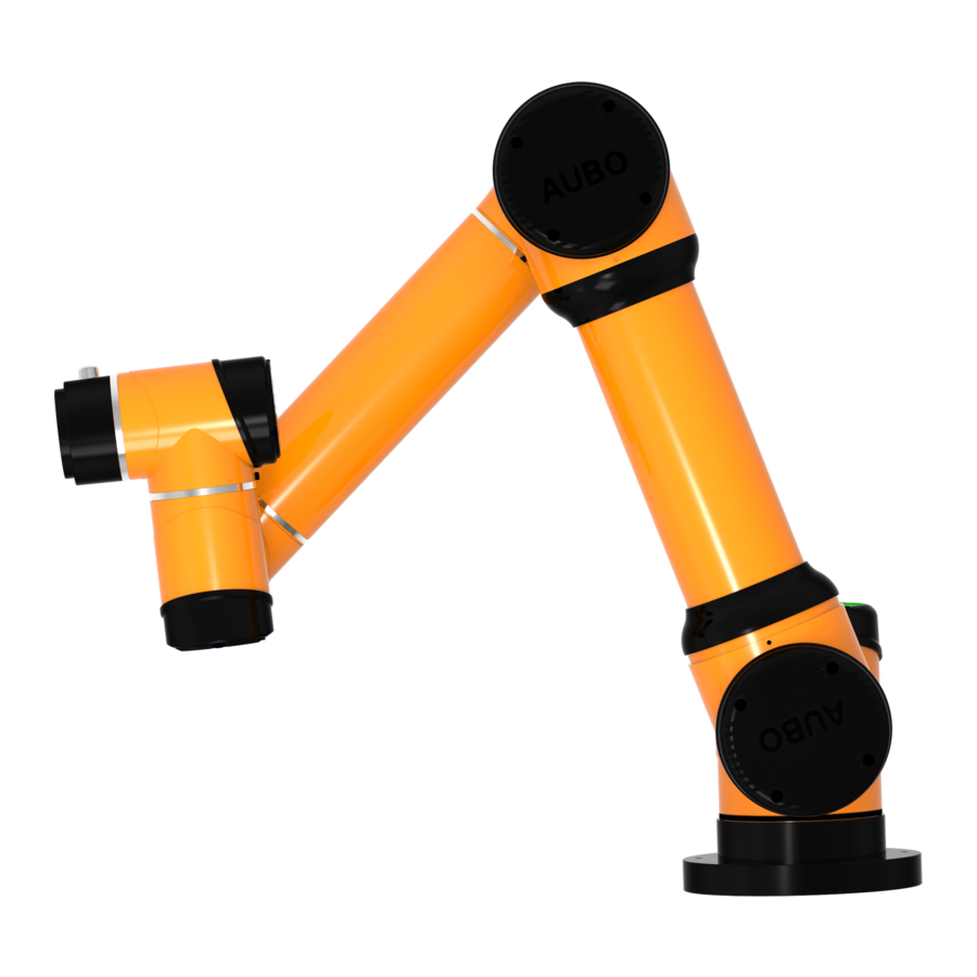
Figure 5.1 AUBO-i5 robot As shown in figure 5.1, The AUBO-i5 robot system consist of a manipulator, a control box(which can choose a variety of models), a manipulator base and a teach pendant. The manipulator imitates human which has six joints and each joint represents a degree of freedom. - Page 32 Figure 5.1 Manipulator Joints Control box is the main control part of AUBO-i5 robot. Please read chapter 8 for any modules inside control box. AUBO-i5 provides multiple I/O interfaces, there are 4-channel digital I/O and 2-channel analog inputs on end-effector flange. Control box communicates with manipulator by CAN-Bus.
-
Page 33: Robot Installation
6. ROBOT INSTALLATION Brief installation steps The installation of AUBO robots includes: 1. Define a robot workspace; 2. Install the robot manipulator on base; 3. Install end-effector Important safety instructions Installation Conditions: •No corrosive gases or liquids •No oil mist •No salt... -
Page 34: Workspace Of The Robot
Install additional equipment: If any additional modules, like cable, which are not provided by AUBO (Beijing) Robotics Technology Co., Ltd., are integrated in industrial robot, users have the responsibility to ensure these modules won’t affect safety function. Workspace of the Robot Mechanical dimensions of manipulator The mechanical dimensions of the manipulator are shown in figure 6.1. -
Page 35: Hardware Installation
Hardware Installation The Manipulator Base AUBO robot manipulator base is shown in figure 6.3. There are 4 anchor bolts and 4 universal wheels for fixing and moving the robot easily. When fixing the robot, rotate the upper part of the foundation bolt and lower it. When moving the robot, use tool (wrench) to rotate the lower part of anchor bolt and raised the bolts to make the universal wheels touch the ground. -
Page 36: Manipulator Installation
Figure 6.4 Mechanical dimensions of the manipulator base structure (left: plan view; right: front view) Manipulator Installation The robot has a function of self-adaption for Installation pose. It can be installed in base, hoisting, mount on wall or any specific installation method, as shown below: ROBOT INSTALLATION V4.3 Page 34 ©2015-2018 AUBO.All rights reserved. - Page 37 Figure 6.6: Mounting whole size of the manipulator base. If installation method is changed (such as choosing hoisting, wall-mounted etc.), after running the AUBOPE and click the “ON” ->” OFF”, then the teach pendant will pop up following window: ©2015-2018 AUBO.All rights reserved. Page 35 ROBOT INSTALLATION V4.3...
- Page 38 IP67 protection class. Tipping hazard. If the robot is not safely placed on a solid surface, the robot can fall over and cause injury. ROBOT INSTALLATION V4.3 Page 36 ©2015-2018 AUBO.All rights reserved.
-
Page 39: End-Effector Installation
1. Make sure the tool is properly and safely bolted in place. 2. Make sure that the tool is constructed such that it cannot create a hazardous situation by dropping a part unexpectedly. ©2015-2018 AUBO.All rights reserved. Page 37 ROBOT INSTALLATION V4.3... - Page 40 ROBOT INSTALLATION V4.3 Page 38 ©2015-2018 AUBO.All rights reserved.
-
Page 41: Getting Started
Installation Installing robots Take out the AUBO robot from the packing box and install it on the base. Please read the specific installation instructions in chapter 6: Installation. 1. Control box should be placed horizontally on the ground. A gap of 50mm on each side is needed for sufficient air circulation 2. -
Page 42: Cable Connection
Plugging the connector into the control box’s connector, and pay attention to the insert direction. After plugging in, lock the connector as shown below in figure 7.2. Figure 7.2 Robot cable connects to control box GETTING STARTED V4.3 Page 40 ©2015-2018 AUBO.All rights reserved. - Page 43 Teach pendant connection The cable of teach pendant has plugs on both sides, as shown in figure 7.5. Connect to teach pendant Connect to control box Figure 7.5 Teach pendant cable ©2015-2018 AUBO.All rights reserved. Page 41 GETTING STARTED V4.3...
- Page 44 Fixed the teach pendant on the side of the control box when you are not using it to avoid drop damage, as shown in figure 7.8. Teach Pendant Figure 7.8 Suspension of teach pendant GETTING STARTED V4.3 Page 42 ©2015-2018 AUBO.All rights reserved.
-
Page 45: Power On The Manipulator
Check whether the emergency stop button on the control box and the teach pendant is pop-up. • Check whether the mode switch key is in right position. • Ensure the robot never hit any personnel or equipment. ©2015-2018 AUBO.All rights reserved. Page 43 GETTING STARTED V4.3... -
Page 46: Power On System
Robot and the teach pendant power-on at same time and the screen of teach pendant lights up. The startup button and the state of LED indicator are shown in figure 7.11 • GETTING STARTED V4.3 Page 44 ©2015-2018 AUBO.All rights reserved. -
Page 47: Power Off The Manipulator
1. Unplugging the power cord directly from the wall outlet to show down the system may result in damage to the robotic file system, which may result in robot malfunction.2. Ensure to unplug the power cord after power off the whole robot system! ©2015-2018 AUBO.All rights reserved. Page 45 GETTING STARTED V4.3... - Page 48 GETTING STARTED V4.3 Page 46 ©2015-2018 AUBO.All rights reserved.
-
Page 49: The I Series Standard Control Box
8. THE I SERIES STANDARD CONTROL BOX Introduction Control box is the control center of AUBO robot, which contains a control board, a safety control board, a switching power supply and a safety protection device. The control box is powered by 100V-240V AC. Its 2 internal switching power supplies convert 100V-240V AC into 12V, 24V and 48V DC which supply power for the load inside control box and the robot. -
Page 50: Electrical Warnings And Cautions
Extremely high signal levels or excessive exposure can damage the robot permanently. EMC problems usually occur in welding processes and are normally prompted by an error messages in the log. AUBO (Beijing) Robotics Technology Co., Ltd is not responsible for the loss caused by the EMC problem. -
Page 51: I Series Control Box's Internal Electrical Interface
Users can easily use these interfaces. The electrical interface of the control box is divided into: safety I/O and general I/O. The AUBO interface board has 16 general digital input interfaces, 16 general digital output interfaces, 4 pairs of analog voltage input interfaces, 2 pairs of analog voltage output interfaces and 2 pairs of analog current output interface. -
Page 52: Safety I/O
The safety I/O designed as dual channel (redundant design) to ensure the safety function shall not lost in any case of single failure. The safety devices and equipment must be implemented in accordance with the safety instruction and finished the comprehensive risk assessment before use. THE I SERIES STANDARD CONTROL BOX V4.3 Page 50 ©2015-2018 AUBO.All rights reserved. - Page 53 Safety Output responding time responding time Robot Emergency Stop 1000ms REDUCED MODE 1000ms Robot Moving 1000ms NOT REDUCED MODE 1000ms Robot Not Stopping 1000ms SYSTEM ERROR 1000ms ©2015-2018 AUBO.All rights reserved. Page 51 THE I SERIES STANDARD CONTROL BOX V4.3...
-
Page 54: Default Safety Configuration
The robot is shipped with a default configuration as below. In this case, the robot can be operated without any additional safety equipment Figure 8.5 Default safety configuration THE I SERIES STANDARD CONTROL BOX V4.3 Page 52 ©2015-2018 AUBO.All rights reserved. -
Page 55: External Emergency Stop Input
In the case that there is required to use one or more external emergency stop buttons, users can connect those devices as below. Figure 8.6 External emergency stop input ©2015-2018 AUBO.All rights reserved. Page 53 THE I SERIES STANDARD CONTROL BOX V4.3... -
Page 56: Safeguard Stop Input
In this mode, the response time of the system is 1200ms. If the user operates too frequently, the system may report an error. • In this configuration, user should select the protective reset as auto-reset via AUBOPE. THE I SERIES STANDARD CONTROL BOX V4.3 Page 54 ©2015-2018 AUBO.All rights reserved. - Page 57 In this mode, the response time of the system is 1200ms. If the user operates too frequently, the system may report an error. • In this configuration, user should select the protective reset as manual reset via AUBOPE. ©2015-2018 AUBO.All rights reserved. Page 55 THE I SERIES STANDARD CONTROL BOX V4.3...
-
Page 58: Reduce Mode Input
• When using this type of configuration, the user needs to configure the reduced mode motion parameters through the AUBOPE. THE I SERIES STANDARD CONTROL BOX V4.3 Page 56 ©2015-2018 AUBO.All rights reserved. -
Page 59: Safeguard Stop Reset Input
The robot continues to run from the stop point. In this process, user needs to use the safeguard stop reset input. When using this type of configuration, the user needs to configure the protective reset as manual reset through the AUBOPE. ©2015-2018 AUBO.All rights reserved. Page 57 THE I SERIES STANDARD CONTROL BOX V4.3... -
Page 60: Enabling Device Input
When using such a configuration, the user is required to ensure that the robot is in verification mode. Users can configure the operating mode through AUBOPE to verification mode, or also through the operation mode input configure the robot to verification mode THE I SERIES STANDARD CONTROL BOX V4.3 Page 58 ©2015-2018 AUBO.All rights reserved. -
Page 61: Operational Mode Input
The user can refer to the following example, using the hand guiding function without the force control button in the teach pendant. Figure 8.13 hand guiding enable input ©2015-2018 AUBO.All rights reserved. Page 59 THE I SERIES STANDARD CONTROL BOX V4.3... -
Page 62: System Stop Input
When one of them enters the emergency stop state, the other will immediately enter the emergency stop state to achieve the function of two machines share emergency stop THE I SERIES STANDARD CONTROL BOX V4.3 Page 60 ©2015-2018 AUBO.All rights reserved. -
Page 63: Robot Emergency Stop Output
In this configuration, when the robot enters the emergency stop state, it outputs a system emergency stop signal and the external alarm light. This function is widely used and, in any case, requires a complete risk assessment by users or Integrators. ©2015-2018 AUBO.All rights reserved. Page 61 THE I SERIES STANDARD CONTROL BOX V4.3... -
Page 64: Robot Moving Output
In this configuration, when the robot moves normally, device outputs the robot moving signal to the outside and the external robot moving status indicator lights. This function is widely used and, in any case, requires a complete risk assessment by users or Integrators. THE I SERIES STANDARD CONTROL BOX V4.3 Page 62 ©2015-2018 AUBO.All rights reserved. -
Page 65: Robot Not Stopping Output
This function is widely used and, in any case, requires a complete risk assessment by users or Integrators. ©2015-2018 AUBO.All rights reserved. Page 63 THE I SERIES STANDARD CONTROL BOX V4.3... -
Page 66: Reduced Mode Output
In this configuration, when the robot enters the reduced mode, it outputs a reduced mode signal and the external reduction mode indicator lights This function is widely used and, in any case, requires a complete risk assessment by users or Integrators. THE I SERIES STANDARD CONTROL BOX V4.3 Page 64 ©2015-2018 AUBO.All rights reserved. -
Page 67: Not Reduced Mode Output
In this configuration, when the robot enters the not reduced mode, it outputs a not reduced mode signal and the external not reduction mode indicator lights This function is widely used and, in any case, requires a complete risk assessment by users or Integrators. ©2015-2018 AUBO.All rights reserved. Page 65 THE I SERIES STANDARD CONTROL BOX V4.3... -
Page 68: System Error Output
In this configuration, when the robot system error alarms, it outputs a system error signal and the external system error indicator light. This function is widely used and, in any case, requires a complete risk assessment by users or Integrators. THE I SERIES STANDARD CONTROL BOX V4.3 Page 66 ©2015-2018 AUBO.All rights reserved. -
Page 69: Internal I/O
Back Up General I/O electrical interface The AUBO interface board has 16 digital input interfaces, 16 digital output interfaces, 4 pairs of analog differential input interfaces, 2 pairs of analog voltage output interfaces and 2 pairs of analog current output interfaces which electrical errors are about ±1%. - Page 70 IO Specification All AUBO robot IOs are set to NPN mode, which means low voltage level effective. When a User IO is set to “Effective” or “High” on the teach pendant, the actual voltage level at the IO output is low.
- Page 71 DI trigger action. Inputting high voltage to DI does not trigger action. DI terminal can read the switch button, sensors, PLC or other AUBO robot operation signals. Some common wirings will be listed in following examples.
- Page 72 "0", DO is connected to GND, and output is high. DO terminals can be connected directly to the load to communicate with PLC or another robot. THE I SERIES STANDARD CONTROL BOX V4.3 Page 70 ©2015-2018 AUBO.All rights reserved.
- Page 73 The control box has four pairs of differential analog input interfaces (Hereinafter use " VI " to represent analog voltage input), and input voltage range is from 0V~+10V, as shown in figure below Figure 8.27 4Analog input External sensor wiring: ©2015-2018 AUBO.All rights reserved. Page 71 THE I SERIES STANDARD CONTROL BOX V4.3...
- Page 74 The common analog voltage output connection method is listed below. Figure 8.29 Analog output drive differential device The common analog current output connection method is listed below. THE I SERIES STANDARD CONTROL BOX V4.3 Page 72 ©2015-2018 AUBO.All rights reserved.
- Page 75 Single VO terminal input voltage +10 V Single CO terminal input current 20 mA When connecting external devices, all external devices should be connected to the ground with the control cabinet. ©2015-2018 AUBO.All rights reserved. Page 73 THE I SERIES STANDARD CONTROL BOX V4.3...
-
Page 76: End-Effector I/O Interface
AI 1 When connecting the tool and the holder, ensure that there is no danger when interrupting the power supply, such as dropping the workpiece from the tool. THE I SERIES STANDARD CONTROL BOX V4.3 Page 74 ©2015-2018 AUBO.All rights reserved. -
Page 77: Communication Interface
Ethernet interface can be used for remoting access and control. USB interface can be used to update, import and export project. Modbus-RTU is used for external communication ©2015-2018 AUBO.All rights reserved. Page 75 THE I SERIES STANDARD CONTROL BOX V4.3... -
Page 78: Getting Started
Check whether the control box and the teach pendant are connected correctly. Check whether the control box connectors are connected correctly. Check anchor bolts on control box support firmly and horizontally. THE I SERIES STANDARD CONTROL BOX V4.3 Page 76 ©2015-2018 AUBO.All rights reserved. -
Page 79: Control Box Panel
TEACH PENDANT Indicator of Teach pendant enable statue. Indicator lights in Manual ENABLE mode. In linkage mode, teach pendant disable when indicator off. ©2015-2018 AUBO.All rights reserved. Page 77 THE I SERIES STANDARD CONTROL BOX V4.3... -
Page 80: Manual Mode And Linkage Mode
Follow the demonstration below, connect the external devices with IO interface on the back of the control box. Users can use the external signals to manipulate the robot. THE I SERIES STANDARD CONTROL BOX V4.3 Page 78 ©2015-2018 AUBO.All rights reserved. - Page 81 Press the button “MODE MANUAL/LINKAGE” on the front panel of the control box. Power the control box. Configure the external devices signals. Then the user can follow the process below to use linkage mode. ©2015-2018 AUBO.All rights reserved. Page 79 THE I SERIES STANDARD CONTROL BOX V4.3...
-
Page 82: Teach Pendant Enable Switch
This works only in Linkage mode. Push the switch on to enter the teach pendant enable mode (default setting). If user wants to remove the teach pendant, user can push the switch down to enter the teach pendant disable THE I SERIES STANDARD CONTROL BOX V4.3 Page 80 ©2015-2018 AUBO.All rights reserved. - Page 83 The teach pendant enable switch is inside of the control box, as illustrated below. Teach pendant enable switch Figure 8.36 Teach pendant enable switch User can only push the switch when the teach pendant power off. ©2015-2018 AUBO.All rights reserved. Page 81 THE I SERIES STANDARD CONTROL BOX V4.3...
- Page 84 THE I SERIES STANDARD CONTROL BOX V4.3 Page 82 ©2015-2018 AUBO.All rights reserved.
-
Page 85: Teach Pendant
9. TEACH PENDANT The teach pendant is an important component of AUBO-i5 robot. Users can acquire information of the robot through the teach pendant, User also can control the manipulator to move and perform simple programming through the teach pendant. -
Page 86: Shut Down The Teach Pendant
• Software: click the shutdown button on the upper right corner of the screen • Power button: press and hold the power button for a while until the teach pendant is powered off. TEACH PENDANT V4.3 Page 84 ©2015-2018 AUBO.All rights reserved. -
Page 87: 10. Teach Pendant User Interface
10. TEACH PENDANT USER INTERFACE The screen shows the user interface after opening the AUBO robot control software. The teach pendant interface consists of 5 panels: Robot Teaching, Programming, Setting, System Info, and About, each panel includes different operation buttons and information displays. Robot Teaching is used for demonstrating the robot manipulation. -
Page 88: End Coordinate System
The Robot Teaching panel is used for the robot teaching operation. User can move the robot by clicking icon on the panel and get feedback information of movements from the panel. This section mainly focuses on the Robot Teaching panel. TEACH PENDANT USER INTERFACE V4.3 Page 86 ©2015-2018 AUBO.All rights reserved. -
Page 89: Software Shut Down Button
10. Robot status control includes zero position, initial position 11. Motion speed control and display, robot time display Software shut down button Click to shut down the software. ©2015-2018 AUBO.All rights reserved. Page 87 TEACH PENDANT USER INTERFACE V4.3... -
Page 90: Menu
:Pan left button :Pan right button :Turn clockwise :Turn counterclockwise :Reset button The simulation model can also be used to validate control programs before applying on the real robot. TEACH PENDANT USER INTERFACE V4.3 Page 88 ©2015-2018 AUBO.All rights reserved. -
Page 91: Simulation/Real Control Switch Button
The end of manipulator is based on the base coordinate system, the end coordinate system or the user-defined coordinate system to control robot movements. The end of manipulator can teach under different coordinate systems. ©2015-2018 AUBO.All rights reserved. Page 89 TEACH PENDANT USER INTERFACE V4.3... -
Page 92: Robot Real-Time Status Parameter Display
The W, X, Y, Z are represented to end pose quaternions. End pose is represented by quaternions, which can also be transformed as other representations (for TEACH PENDANT USER INTERFACE V4.3 Page 90 ©2015-2018 AUBO.All rights reserved. -
Page 93: Orientation Control
Users can add new option to the drop-down menu by the TCP Setting- Tool coordinate system settings Orientation Control Figure 10.12 Orientation Control (base) Figure 10.13 Orientation Control (end) ©2015-2018 AUBO.All rights reserved. Page 91 TEACH PENDANT USER INTERFACE V4.3... -
Page 94: Joint Axis Control
Init Pose: Press and hold the button to back to the initial pose. Users can set arbitrary initial pose by 【Robot Settings】->【InitPose】on the teach pendant interface. Figure 10.16 Zero Pose and Init Pose (default) TEACH PENDANT USER INTERFACE V4.3 Page 92 ©2015-2018 AUBO.All rights reserved. -
Page 95: Motion Speed Control
Internal I/O: only for internal function interface to provide status display of the internal I/O which are not available for user. Linkage I/O: for linkage mode I/O status display. ©2015-2018 AUBO.All rights reserved. Page 93 TEACH PENDANT USER INTERFACE V4.3... -
Page 96: User I/O
This section introduces the setting of I/O interface provided by the teach pendant. For the detailed description of the interface, please refer to electrical interface Manual. I/O settings panel includes tool I/O tab, controller I/O tab and PLC I/O tab. TEACH PENDANT USER INTERFACE V4.3 Page 94 ©2015-2018 AUBO.All rights reserved. - Page 97 0v, 12V and 24V. Users need to configure the voltage of pin 2 and states of pin 3/4/5/6 based on the actual usage before using this function. ©2015-2018 AUBO.All rights reserved. Page 95 TEACH PENDANT USER INTERFACE V4.3...
-
Page 98: Robot Setting Tab
Click【Set InitPose】to set the initial position by moving robot via the teach pendant or hand guiding, which correspond to【Init Pose】on the interface, and synchronize to the【Init Pose】below the teaching interface after setting. TEACH PENDANT USER INTERFACE V4.3 Page 96 ©2015-2018 AUBO.All rights reserved. -
Page 99: Tool Calibration
After calibrating the kinematic and kinematic parameters of the tool, enter the tool calibration interface, select a kinematic and dynamics attributes for the tool, enter the name of the tool, and then add the tool. ©2015-2018 AUBO.All rights reserved. Page 97... -
Page 100: Tool Kinematics Calibration
Y-axis, ensure that the angle formed by the three waypoints is at right angles. During the calibration process, move to the reference position first, select Point Type as Ori Calibration, and click Add to enter the TEACH PENDANT USER INTERFACE V4.3 Page 98 ©2015-2018 AUBO.All rights reserved. - Page 101 Delete button to finish the deletion. Need to pay attention to, kinematics parameter flange_center option is the system default parameters, which cannot be modified and deleted. ©2015-2018 AUBO.All rights reserved. Page 99 TEACH PENDANT USER INTERFACE V4.3...
-
Page 102: Tool Dynamics Calibration
When deleting the tool dynamic parameters, first select the item to be modified, and then click the Delete button to delete. It should be noted that, flange_center option is the system default parameter, which cannot be modified and deleted. TEACH PENDANT USER INTERFACE V4.3 Page 100 ©2015-2018 AUBO.All rights reserved. -
Page 103: Tool Calibrate
It may cause different malfunctions if setting data is inaccurate in the actual operation. If the setting is wrong, the manipulator and the control box can’t work normally and can cause danger to personnel or equipment around. ©2015-2018 AUBO.All rights reserved. Page 101 TEACH PENDANT USER INTERFACE V4.3... -
Page 104: Coordinate Calibration
Figure 10.28 XOY The figure above is xOy type, the first point requires for the calibration is the origin of the coordinate system, TEACH PENDANT USER INTERFACE V4.3 Page 102 ©2015-2018 AUBO.All rights reserved. - Page 105 The second point is any point on the positive of the Z-axis, and the third point is any point on the positive semi-axis of the X-axis. The angle formed by the three points is a right angle. ©2015-2018 AUBO.All rights reserved. Page 103...
- Page 106 X-axis, and the third point is formed at any point within the first quadrant of the xOz plane. The angle formed by the three points is an acute angle. TEACH PENDANT USER INTERFACE V4.3 Page 104 ©2015-2018 AUBO.All rights reserved.
- Page 107 Y-axis, and the third point is formed at any point within the first quadrant of the yOx plane. The angle formed by the three points is an acute angle. ©2015-2018 AUBO.All rights reserved. Page 105...
- Page 108 Coordinate system name can also be modified, after setting up, click the Modify button, and save the modified parameters. When you delete a coordinate system, select the coordinate system on the list and click the Delete button. The coordinate system is removed. TEACH PENDANT USER INTERFACE V4.3 Page 106 ©2015-2018 AUBO.All rights reserved.
-
Page 109: Safety
Operational mode: When "Normal mode" is selected, the external enabling device input signal is invalid. When "verification mode" is selected, the external enabling device input signal is valid. ©2015-2018 AUBO.All rights reserved. Page 107 TEACH PENDANT USER INTERFACE V4.3... -
Page 110: System Settings Tab
The Robot Setting tab has nine units, including Languages, Date& Time, Password, Lock Screen and Update. Language Tab Figure 10.38 Language Tab Language Tab provides English (default), Simplified Chinese, Japanese, French, German, and Slovak. TEACH PENDANT USER INTERFACE V4.3 Page 108 ©2015-2018 AUBO.All rights reserved. -
Page 111: Date& Time Tab
Date& Time tab. Figure 10.39 Date& Time tab. Date& Time tab can set date and time. ©2015-2018 AUBO.All rights reserved. Page 109 TEACH PENDANT USER INTERFACE V4.3... -
Page 112: Network Tab
The network IP address of the external device should in the same network segment with the IP address of the robot. Restart the AUBOPE system after saving the configuration TEACH PENDANT USER INTERFACE V4.3 Page 110 ©2015-2018 AUBO.All rights reserved. -
Page 113: Password Tab
Users can set screen lock (default password is 1) and the time of screen lock in Password Tab. Click【set password】to update the settings. The teach pendant can only be used under right password. ©2015-2018 AUBO.All rights reserved. Page 111 TEACH PENDANT USER INTERFACE V4.3... -
Page 114: System
System Figure 10.42 Lock Screen Input the time of screen lock to update screen lock. TEACH PENDANT USER INTERFACE V4.3 Page 112 ©2015-2018 AUBO.All rights reserved. -
Page 115: Update Tab
USB disk format supports FAT32 but does not support NTFS format. Factory Reset means that all the information and data are cleared and returned to the factory state. Do not ©2015-2018 AUBO.All rights reserved. Page 113 TEACH PENDANT USER INTERFACE V4.3... - Page 116 You can use File Export to export your Log and Project: Insert USB drive and click Scan Device, select the inserted U disk, then you can export your Log and Project. TEACH PENDANT USER INTERFACE V4.3 Page 114 ©2015-2018 AUBO.All rights reserved.
-
Page 117: Extensions
Click Delete to delete the entries on the list. In the IO status interface, the IO status can be displayed, and the output IO status can also be configured. ©2015-2018 AUBO.All rights reserved. Page 115 TEACH PENDANT USER INTERFACE V4.3... - Page 118 TEACH PENDANT USER INTERFACE V4.3 Page 116 ©2015-2018 AUBO.All rights reserved.
- Page 119 Add the PickIt 3D vision system to the teach pendant software; • ©2015-2018 AUBO.All rights reserved. Page 117 TEACH PENDANT USER INTERFACE V4.3...
- Page 120 Add Camera plugin to the teach pendant software; • TEACH PENDANT USER INTERFACE V4.3 Page 118 ©2015-2018 AUBO.All rights reserved.
- Page 121 Added palletizing process package to the teach pendant software; • ©2015-2018 AUBO.All rights reserved. Page 119 TEACH PENDANT USER INTERFACE V4.3...
-
Page 122: System Info Tab
The format of Robot Log: date, time, information category and information description. When the robot system is operating irregularly, users can check logs by slide and the slide bar on the right to find out problems. TEACH PENDANT USER INTERFACE V4.3 Page 120 ©2015-2018 AUBO.All rights reserved. -
Page 123: About
Version unit is used for the version information of software and other hardware. Corresponding version in this manual is shown in table below: version information version number AUBOPE version V4.3 Interface board version V3.2 ©2015-2018 AUBO.All rights reserved. Page 121 TEACH PENDANT USER INTERFACE V4.3... - Page 124 TEACH PENDANT USER INTERFACE V4.3 Page 122 ©2015-2018 AUBO.All rights reserved.
-
Page 125: 11. Online Programming
Introduction AUBO-i5 robot provides convenient programming method in Online Programming Interface. Users can program AUBO-i5 based on a little programming skill, which can improve work efficiency greatly. Users can program AUBO-i5 in ONLINE PROGRAMMING Tab, which includes 3 parts: Program logic list, which are arranged in a tree structure for users to read and modify programs. -
Page 126: Project Tab
When a new project is created, it will cover the current project. Therefore, remember to save the current project. Click【Add before】to insert a new command before selected command. Click【Add after】to insert a new command after selected command. Figure 11.1 Project tab ONLINE PROGRAMMING V4.3 Page 124 ©2015-2018 AUBO.All rights reserved. -
Page 127: Load Project
Click【Start】button on the lower left corner to enter auto move tab. Press and hold【Auto】button to move robot to initial pose. Click【OK】->【Start】, the robot will start to move. Figure 11.2: Project tab. ©2015-2018 AUBO.All rights reserved. Page 125 ONLINE PROGRAMMING V4.3... -
Page 128: Save Project
If saved project need to be edited, click【Save Project】again. Saved project can be exported by clicking 【Robot Settings】 -> 【Update】 in the teach pendant interface. See 10.5.7 Update. Figure 11.3 Save project ONLINE PROGRAMMING V4.3 Page 126 ©2015-2018 AUBO.All rights reserved. -
Page 129: Default Project
Click【auto load and run default project】to load and operate the default project automatically after opening the programming environment. Click【Confirm】button to confirm the default project configuration. Figure 11.4 Default Project ©2015-2018 AUBO.All rights reserved. Page 127 ONLINE PROGRAMMING V4.3... -
Page 130: Auto Move Tab
Auto move: Press and hold【Auto】button to operate robot to current position. Note: Release the button to stop the motion at any time. Figure 11.5 Auto move Figure 11.6 Manually move Manually move: Press【Manual】button to jump into the teaching interface, which can move robot manually. ONLINE PROGRAMMING V4.3 Page 128 ©2015-2018 AUBO.All rights reserved. -
Page 131: Procedure
New Project, Load Project, and Save Project method are the same as project section. The established sub-project file can be applied to the Procedure command. Figure 11.7 Procedure Project ©2015-2018 AUBO.All rights reserved. Page 129 ONLINE PROGRAMMING V4.3... -
Page 132: Command & Condition Tabs
If command. When If condition is true, Break will be executed and jump out of the loop. Otherwise, an error message will pop up. Click【Remove】to delete the Break command. Figure 11.9 Break ONLINE PROGRAMMING V4.3 Page 130 ©2015-2018 AUBO.All rights reserved. - Page 133 If command before Continue. When condition in If is satisfied, then execute Continue to jump out of the loop for one time. Otherwise, an error message will pop up. Click【Remove】to delete the Continue command. Figure 11.10 Continue ©2015-2018 AUBO.All rights reserved. Page 131 ONLINE PROGRAMMING V4.3...
- Page 134 Click【Add ElseIf】to add an ElseIf node. One【If】command can add multiple Else If nodes. Click【Remove】to delete【If】command. All ElseIf nodes and Else nodes will be deleted together. Click【Confirm】to confirm and save the configurations. Figure 11.11 If…Else Figure 11.12 If…Else expression box ONLINE PROGRAMMING V4.3 Page 132 ©2015-2018 AUBO.All rights reserved.
-
Page 135: Switch
Click【Add Default】to add a Default node. One Switch can only add one Default. Click【Remove】to delete the selected Switch, and the corresponding Case and Default of this switch will also be deleted. Click【Confirm】to confirm the configurations and save. Figure 11.13 switch…case…default command ©2015-2018 AUBO.All rights reserved. Page 133 ONLINE PROGRAMMING V4.3... -
Page 136: Set
If these settings are wrong, the manipulator and control box will not function correctly and may become dangerous to people or equipment around them. Wait Wait command is used to set waiting time or digital input signals. ONLINE PROGRAMMING V4.3 Page 134 ©2015-2018 AUBO.All rights reserved. -
Page 137: Timer
Clicking【Alias】to the right of the blank interface will pop up the input box. You can modify the command name. Click【Comment】to input text to explain the following block. Click【Remove】to delete the selected Line Comment. Click【Confirm】to confirm the configurations and save. ©2015-2018 AUBO.All rights reserved. Page 135 ONLINE PROGRAMMING V4.3... -
Page 138: Block Comment
The robot is programed to move from A to B, yet it receive a signal F on its way to B, it stops moving towards B and goes immediately to C. GOTO command is designed to interrupt the current movement. It must be used in the thread program. A demo project is seen as below. ONLINE PROGRAMMING V4.3 Page 136 ©2015-2018 AUBO.All rights reserved. -
Page 139: Message
Click 【Stop project when this message box pops up】, the project will stop automatically when the information window pops up. Click 【Remove】 to delete the selected message. Click 【Confirm】to confirm the configurations and save. ©2015-2018 AUBO.All rights reserved. Page 137 ONLINE PROGRAMMING V4.3... -
Page 140: Empty
Click【Move】to add a new Move node to the program list and a Waypoint sub-node will be added automatically. Choose【Move】node, Condition Tabs will automatic pop-up, as shown in Figure 11.8. Users can configure the proceeding status of the Move command. ONLINE PROGRAMMING V4.3 Page 138 ©2015-2018 AUBO.All rights reserved. - Page 141 100 mm. The operating characteristic of the blend radius is a continuous motion and does not stop at this waypoint. The blend radius runs as shown below. Figure 11.20 Blend radius moving track ©2015-2018 AUBO.All rights reserved. Page 139 ONLINE PROGRAMMING V4.3...
- Page 142 TCP’s moving path, this movement type is a good choice. Move Joint applies for the enough space and moves by the fastest way. As shown below. Figure 11.21 Move Joint track ONLINE PROGRAMMING V4.3 Page 140 ©2015-2018 AUBO.All rights reserved.
- Page 143 Maximum speed of motor is 3000rpm. It is recommended that the speed is no more than 2800rpm in actual use. Maximum acceleration of motor (added speed per second) is 20000rpm/s. The joint’s speed is motor speed / speed ratio. The speed ratio of Joint 1~3, 4~6 in AUBO-i5 are 121 and 101. ...
- Page 144 Move Line. When the Cir is selected in the MoveTrack type, the robot moves in a circular motion. ArcWithOriRot/CirWithOriRot: In industrial secenaios, especially welding applications, users ONLINE PROGRAMMING V4.3 Page 142 ©2015-2018 AUBO.All rights reserved.
- Page 145 When there are Loop commands in the program logic list, the first waypoint of the first Move command must be the same as the last waypoint of the last Move command. Figure 11.24 Move Track ©2015-2018 AUBO.All rights reserved. Page 143 ONLINE PROGRAMMING V4.3...
-
Page 146: Waypoint
Waypoint Waypoint is an important part of AUBO-i5 program, which represents the position that the end- effector needs to arrive. Usually, the trajectory of the end consists of two or more waypoints. Waypoint can only be added after【Move】command. -
Page 147: Procedure
Click【Update】as the file update button to retrieve the current file save directory and update the display file changes. Click【Remove】to delete the selected procedure. Click【Confirm】to confirm the configurations and save. Figure 11.27 Procedure ©2015-2018 AUBO.All rights reserved. Page 145 ONLINE PROGRAMMING V4.3... -
Page 148: Script
Click【Update】as the file update button to retrieve the current file save directory and update the display file changes. Click【Remove】to delete the selected Thread. Click【Confirm】to confirm configuration and save. ONLINE PROGRAMMING V4.3 Page 146 ©2015-2018 AUBO.All rights reserved. -
Page 149: Record Track
Please click 【confirm】 button after modification. Click【Update】as the file update button to retrieve the current file save directory and update the display file changes. Click【Remove】to delete the selected Track_Record. ©2015-2018 AUBO.All rights reserved. Page 147 ONLINE PROGRAMMING V4.3... -
Page 150: Offline Record
The imported trace file suffix should end with “.offt.” The import file needs to be copied to the folder to be displayed in AUBORPE software interface, as shown in the following figure: Figure 11.31 import offline file ONLINE PROGRAMMING V4.3 Page 148 ©2015-2018 AUBO.All rights reserved. - Page 151 Figure 11.32 Offline Record ©2015-2018 AUBO.All rights reserved. Page 149 ONLINE PROGRAMMING V4.3...
-
Page 152: Track Record
During the replay, User can drag progress bar to operate the replay progress. Edit track: click Cut Before to remove the track before selected position, click Cut After to remove the track after selected position. ONLINE PROGRAMMING V4.3 Page 150 ©2015-2018 AUBO.All rights reserved. -
Page 153: Variable Tab
After completing the waypoint setting, click [OK] to complete the variable. Global hold: Sets the current variable as a global variable. ©2015-2018 AUBO.All rights reserved. Page 151 ONLINE PROGRAMMING V4.3... -
Page 154: Timer
Timer1 and Timer2 are the nodes specified in the project, time underlines the time intervals between the beginning and node Timer1 and between Timer1 and Timer2. ONLINE PROGRAMMING V4.3 Page 152 ©2015-2018 AUBO.All rights reserved. -
Page 155: Simulation Model
3D model, including the position parameter XYZ and the rotate parameters: RX RY RZ. Users can check "Show track" and see the end of the track in the simulation window. Users can also set the Track duration to specify the track display time. ©2015-2018 AUBO.All rights reserved. Page 153 ONLINE PROGRAMMING V4.3... -
Page 156: Scripts File Configuration
Figure 11.37 Simulation model Scripts file configuration Online programming function can help the user to new, edit, load and save scripts. Note: scripts should comply with LUA grammar, otherwise cannot be saved. ONLINE PROGRAMMING V4.3 Page 154 ©2015-2018 AUBO.All rights reserved. - Page 157 Figure 11.38 script file editor ©2015-2018 AUBO.All rights reserved. Page 155 ONLINE PROGRAMMING V4.3...
- Page 158 ONLINE PROGRAMMING V4.3 Page 156 ©2015-2018 AUBO.All rights reserved.
-
Page 159: Appendix
Performance Level: A Performance Level (PL) is a discrete level used to specify the ability of safety-related parts of control systems to perform a safety functions under foreseeable conditions. PLd is the second highest reliability classification, meaning that the safety function is extremely reliable. For more information, see EN ISO13849-1:2008. ©2015-2018 AUBO.All rights reserved. APPENDIX V4.3... -
Page 160: B Certification
CE certification, North American certification and KCS certification, as well as EN ISO 13849 and EN ISO 10218. Its product safety has reached the international advanced level. AUBO- i5 passed the robotic performance test of China National Robot Testing and Assessment Center (headquarters). - Page 161 AUBO-i5 robot was certified by a Korean official agency and passed KCs certification. It meets all the relevant requirements of the Korean certification standard. AUBO-i5 robot was certified by the China National Robot Testing and Assessment Center (headquarters) and has been certified with CR...
-
Page 162: C Stopping Time & Stopping Distance
During the tests for Join 1 and 2, the robot follows a vertical trajectory, which means the axes of rotation is parallel to the ground and stop when the robot moving downwards. Stopping Stopping Distance(rad) Time(ms) Joint 0 (BASE) 0.21 Joint 1 (SHOULDER) 0.60 Joint 2 (ELBOW) 0.12 APPENDIX V4.3 ©2015-2018 AUBO.All rights reserved. -
Page 163: D Guideline
General principles of design, risk assessment and risk reduction EN ISO 10218-1:2011 Industrial robots: Safety Note: Content equivalent to ANSI/RIA R.15.06-2012, Part 1 ISO/TS 15066: 2016 Safety requirements for collaborative industrial robot Robots and robotic devices —Collaborative robots ©2015-2018 AUBO.All rights reserved. APPENDIX V4.3... -
Page 164: E Technical Specification
Robot can work in a temperature range of 0-45º C Temperature 25%-85% Relative humidity Power supply 100-240 VAC, 50-60 Hz Lifetime 30,000 hours Cabling Cable between robot and control box (2.9m) Cable between touchscreen and control box (2.9m) APPENDIX V4.3 ©2015-2018 AUBO.All rights reserved. -
Page 165: F Payload
1. The load conditions should within the range shown in the figure. 2. The payload shown in figure represent maximum load capacity. Shall not overload in any case. 3. Overload may cause damage to the machine's internal parts ©2015-2018 AUBO.All rights reserved. APPENDIX V4.3... -
Page 166: G Manipulator Installation Requirements
Mounting Normal Emergency stop operation Forward 1554N± 360N 1554N± 2594N mounting Reverse 1754N± 360N 1754N± 2594N mounting Vertical 1554N± 360N 1554N± 2594N mounting Make sure to meet requirements when installation. APPENDIX V4.3 VIII ©2015-2018 AUBO.All rights reserved. - Page 167 Joint 2 can 1. Joint 2 circuit bus error! Check CAN bus Joint 2 can bus board error. 40002 Please check connection between error. 2. CAN bus can bus module 1 and module 2. error. cable! ©2015-2018 AUBO.All rights reserved. APPENDIX V4.3...
- Page 168 Across across Irregular 60001 irresolvable Re-planned trajectory. irresolvable movement. singularity. singularity!") "Cartesian Over speed motion--- protection for over speed bad inverse Irregular 60002 Re-planned trajectory. protection kinematic movement. for bad solution of inverse singularity. APPENDIX V4.3 ©2015-2018 AUBO.All rights reserved.
- Page 169 -last target point target point Irregular Re-planned end close to 60007 close to movement. waypoint. irresolvable irresolvable singularity. singularity!") "MoveP--- MoveP---zero Re-planned non-zero zero blend blend radius is Stop movement. 60008 blend radius radius unsupported. ©2015-2018 AUBO.All rights reserved. APPENDIX V4.3...
- Page 170 60014 protection protection for Stop movement. Re-planned trajectory. for Cartesian track. motion"); "Relative linear relative linear motion--- motion---target target point Irregular point close to Re-planned trajectory. 60015 close to movement. irresolvable irresolvable singularity singularity!") APPENDIX V4.3 ©2015-2018 AUBO.All rights reserved.
- Page 171 Speed mutates Check whether in 70005 over speed over speed at some speed. singularity. Control box robot power Control box servo power robot power off servo power 70006 down. ©2015-2018 AUBO.All rights reserved. XIII APPENDIX V4.3...
- Page 172 5. Interface board hardware error. Code Following are error First number Remark example number 1-Joint problem 2-Tool IO problem 3-Interface board problem Explan XXXXX 4-Bus problem Error number ation 5-Software problem 6-Programming problem 7- General alarm APPENDIX V4.3 ©2015-2018 AUBO.All rights reserved.
- Page 173 Warranty claims must be made directly to AUBO within thirty (30) days from the date Purchaser discovers a defect in the Robot. This Limited Warranty does not cover any Robot (i) purchased through non-authorized dealers;...
- Page 174 (a) normal wear and tear; (b) modification or alteration without AUBO’s prior written consent; (c) accident, misuse, excessive exposure to water; (d) use of an accessory not approved by AUBO; (e) failure to follow AUBO's [Product Safety Instructions or User’s Manual]; or (f) service made or attempted by anyone other than an authorized service provider of AUBO.
- Page 175 Warranty Disclaimers. EXCEPT AS EXPRESSLY SET FORTH ABOVE, EACH ROBOT IS PROVIDED SOLELY ON AN "AS IS" BASIS AND AUBO MAKES NO OTHER WARRANTIES OF ANY KIND. TO THE MAXIMUM EXTENT PERMITTED BY APPLICABLE LAW, AUBO SPECIFICALLY DISCLAIMS AND EXCLUDES ANY AND ALL OTHER...
- Page 176 Industrial AUBO-i5 axis payload reach Collaborative Lightweight Robot Made for Human Centric Agile Manufacturing Versatile–Flexible–User Friendly Low Cost–Lightweight NRTAC www.aubo-robotics.com...
- Page 177 AUBO-i5 Collaborative Robot (Co-Bot) AUBO Robots work closely within the human environment without the need for safety equipment, depending on risk assessment. COLLABORATIVE FUNCTION: • Hand guide-to-teach (inverse kinematics motion planning), this manual operation of the robot enables quick and easy programing by demonstration without any programing skills.
- Page 178 AUBO-i5 Collaborative Robot (Co-Bot) Work Envelope-Range of Motion of the Point P View along the Z View along the X or Y coordinate direction coordinate direction Ø490 (X-Y Plane) Motion Area of Point P Point P Point P (XZ/YZ Plane)
- Page 179 Lifetime 30000 h Collaboration Collaborative operation according to ISO 10218-1 :2001 Certification Compliance with EU CE certification, North American certification, Korean KCs certification AUBO-i5 Repeatability +/- 0.02 mm Linear Velocity = 2.8 m/s < Power Consumption 200 W (under normal working conditions)
- Page 180 API for both industrial and academic uses. The Aubo i Series of robots use the CAN bus networks to communicate between joints. Low cost of ownership and high positional repeatability are some of the other criteria that makes up the outstanding features of this robot.
- Page 181 Case Polishing Assembly Product Testing Machine Tending Education Load/Unload Dispensing Aubo Robotics USA Aubo Robotics China 2704 Cherokee Farm Way, Suite 203 3rd Floor, Shilong Sunshine Building Knoxville, TN 37920 USA No.98 of Lianshihu West Road, Bejing, China P: 001-865-500-7144...
Need help?
Do you have a question about the i5 and is the answer not in the manual?
Questions and answers