Table of Contents
Advertisement
Quick Links
USER GUIDE AND SPECIFICATIONS
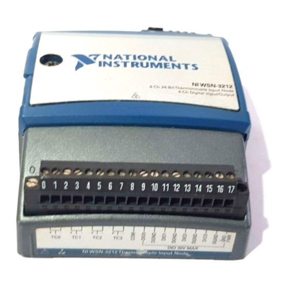
NI WSN-3212
NI Wireless Sensor Network 4-Channel, 24-Bit Thermocouple Input Node
This user guide describes how to use the NI WSN-3212 thermocouple input node and lists its
specifications. Figure 1 shows the NI WSN system components.
1
1
NI WSN-32xx Nodes
2
NI 9792 WSN Real-Time Gateway
The NI WSN-3212 is a four-channel, low-power, wireless thermocouple input device that works with
other NI WSN-32xx nodes and gateways to form a wireless sensor network. The NI WSN system
consists of one or more NI WSN gateways, up to 36 NI WSN-32xx nodes per gateway, and multiple PCs
or Programmable Automation Controllers (PACs) to receive and analyze the distributed sensor data. For
more information about PACs, visit
2
Or
1
3
NI WSN-9791 Ethernet Gateway
4
PC Running NI Software
Figure 1. NI WSN System Components
.
ni.com
4
3
Advertisement
Table of Contents

Related Manuals for National Instruments WSN-3212


Summary of Contents for National Instruments WSN-3212
- Page 1 USER GUIDE AND SPECIFICATIONS NI WSN-3212 NI Wireless Sensor Network 4-Channel, 24-Bit Thermocouple Input Node This user guide describes how to use the NI WSN-3212 thermocouple input node and lists its specifications. Figure 1 shows the NI WSN system components. NI WSN-32xx Nodes...
- Page 2 When you connect the NI WSN gateway, you can use a separate host PC running Windows, or a PAC running NI LabVIEW Real-Time, to display measurement results, status information, and to change the NI gateway and NI WSN-3212 device settings. Figure 2 shows the NI WSN-3212 device block diagram. Antenna Battery Input 2.4 GHz...
-
Page 3: Safety Guidelines
(2.00 in.) Figure 3. NI WSN-3212 Device Dimensions Safety Guidelines Operate the NI WSN-3212 device only as described in this user guide. Hot Surface This icon denotes that the component may be hot. Touching this component may result in bodily injury. -
Page 4: Safety Guidelines For Hazardous Locations
Safety Guidelines for Hazardous Locations The NI WSN-3212 is suitable for use in Class I, Division 2, Groups A, B, C, D, T4 hazardous locations; Class I, Zone 2, AEx nC IIC T4 and Ex nL IIC T4 hazardous locations; and nonhazardous locations only. -
Page 5: Related Documentation
NI WSN-9791 Ethernet Gateway User Guide and Specifications • NI 9792 WSN Real-Time Gateway User Guide and Specifications • Configuring WSN in MAX, available from Start»All Programs»National Instruments»NI-WSN • LabVIEW Help for WSN Devices, available in LabVIEW from Help»LV Help» WSN Devices Help •... -
Page 6: Software Overview
Networks, and then select the latest version of NI-WSN software. If you are using other software, refer to the installation instructions that accompany your software. What You Need to Get Started To set up and use NI LabVIEW with the NI WSN-3212 device, you need the following: • NI WSN gateway •... - Page 7 Figure 4. Attach the Antenna to the Device Mounting the NI WSN-3212 Device You can mount the NI WSN-3212 on a panel or on a 35 mm DIN rail. For kit accessory ordering information, refer to the NI WSN product page accessory section at .
- Page 8 DIN rail clip to the NI WSN-3212. Caution Do not use screws longer than 5/16 in. to fasten the DIN rail clip to the NI WSN-3212. Figure 5. NI WSN-3212 Device DIN Rail Installation Insert one edge of the DIN rail into the deeper opening of the DIN rail clip, as shown in Figure 6.
- Page 9 I/O wires. You can use the NI WSN-3280 panel mount accessory to attach the NI WSN-3212 device to a panel or other flat surface. The NI WSN-3281 panel mount accessory also includes a magnetic mount for attaching the NI WSN-3212 device to metallic surfaces.
- Page 10 Mounting Hole Figure 8. Panel Mount Accessory Refer to Figure 8 while completing the following steps to mount the NI WSN-3212 on a panel: (NI WSN-3280) Bolt or screw the panel mount accessory to a panel using five 8-32 or M4 screws.
- Page 11 Slide the retention clip down and tighten the panel mount knob to secure the NI WSN-3212 device as shown in Figure 9. NATIONAL NATIONAL INSTRUMENTS INSTRUMENTS Figure 9. Slide Retention Clip Down and Tighten Panel Mount Knob (Optional) Secure any I/O signal or power supply cabling to the panel mount accessory using a zip-tie and the integrated strain relief slots.
-
Page 12: Installing The Software
Using the Integrated Panel Mount Slots You can also mount the NI WSN-3212 to a panel using the integrated panel mount slots as shown in Figure 10. Attach three number 8 or M4 pan head screws in the mounting panel leaving 0.1 in. space under the head of each screw. -
Page 13: Installing Batteries
If both battery and external power are connected, the NI WSN-3212 functions from the external power input. The device is designed to provide battery backup in the event of loss of external power and will automatically switch to battery power when external power is lost. - Page 14 Reinstall the 2-position mini-combicon plug in the device and tighten the retaining screws. Caution You must use a UL Listed ITE power supply marked LPS with the NI WSN-3212. The power supply must also meet any safety and compliance requirements for the country of use.
-
Page 15: Device Interface
Device Interface Figure 13 shows the NI WSN-3212 device interface. WSN Connect Button Reset Button Signal Strength/Status LEDs Battery Slots/Polarity Indicators User LED I/O Connector 9–30 V External Power Input Antenna Figure 13. NI WSN-3212 Node Interface © National Instruments Corporation... - Page 16 Signal Strength/Status LED Indicators The NI WSN-3212 has four signal strength/status LED indicators, which flash twice before displaying signal strength information. Table 1 shows the status and signal strength LED patterns. Table 1. Signal Strength and Status LED State/Node Status...
-
Page 17: Reset Button
Refer to your NI WSN gateway documentation for detailed instructions about how to connect a NI WSN-3212 to the NI WSN gateway. The NI WSN-3212 is equipped with a WSN connect button as shown in Figure 13. The button controls network connection and the LEDs, which display connection status. -
Page 18: Connecting Thermocouples
Figures 17 through 21 shows the typical and maximum errors for the different thermocouple types when used with the NI WSN-3212 over the full temperature range. The figures account for gain errors, offset errors, differential and integral nonlinearity, quantization errors, noise errors, and isothermal errors. - Page 19 For the best accuracy results, keep temperature gradients across NI WSN-3212 terminals to a minimum. Refer to the Minimizing Thermal Gradients section for more information. 1000 1200 1400 1600 1800 Measured Temperature (˚ C ) Max, –40 to 70 ˚ C Typ, –40 to 70 ˚...
- Page 20 Figure 19. Type K Errors –200 1000 1200 1400 1600 1800 Measured Temperature (˚ C ) Max, –40 to 70 ˚ C Typ, –40 to 70 ˚ C Figure 20. Type R and S Errors NI WSN-3212 User Guide and Specifications ni.com...
- Page 21 If the system is mounted as recommended in the WSN device user guides, the NI WSN-3212 accuracy specifications include the errors caused by the gradient across the device terminals.
- Page 22 NI WSN-3212. You can connect sourcing digital outputs to the NI WSN-3212 in either Drive High Only Mode or Drive High and Low Mode. In either mode, connect the device to DIO.x and connect the device common to the D GND terminal closest to that DIO.x terminal.
- Page 23 External DIO. x Power Device (Internal) Supply – Low Side Switch D GND NI WSN-3212 Figure 24. Connecting a Device to the NI WSN-3212 in Drive High and Low Mode © National Instruments Corporation NI WSN-3212 User Guide and Specifications...
- Page 24 Supply D GND NI WSN-3212 Figure 25. Connecting a Device to the NI WSN-3212 in Drive Low Only Mode Connecting Digital Inputs Tristate Mode Use this mode to configure the channel as digital input, or for contact to ground sensing, as shown in Figure 26.
- Page 25 After you have identified and removed the cause of the overcurrent condition, to resume normal operation, you must reset the node by pressing the RESET button or by removing and reapplying power to the node. © National Instruments Corporation NI WSN-3212 User Guide and Specifications...
-
Page 26: Specifications
Common-mode rejection ratio (0 to 60 Hz) Channel-to-common ........95 dB Temperature measurement ranges Thermocouple types J, K, R, S, T, N, and B ..........Works over temperature ranges defined by NIST Thermocouple type E........–270 to 950 °C NI WSN-3212 User Guide and Specifications ni.com... - Page 27 Total DIO current (all channels) ......0.5 A maximum Output current (one channel) (I ) ......0.5 A maximum Output voltage × – 0.5 V – (0.9 Ω Sourcing ............V ) minimum DIO PWR × Sinking ............0.9 Ω maximum © National Instruments Corporation NI WSN-3212 User Guide and Specifications...
-
Page 28: Wireless Characteristics
Connector............Female RP-SMA connector VSWR............MAX.2.0 Impedance ............50 Ω Directivity ............Omni Nominal gain..........1.5 dBi Due to regulations, the frequency bands depend upon country of operation. Due to regulations, the valid channels depend upon country of operation. NI WSN-3212 User Guide and Specifications ni.com... -
Page 29: Power Requirements
External Power Caution You must use a UL Listed ITE power supply marked LPS with the NI WSN-3212. The power supply must also meet any safety and compliance requirements for the country of use. Voltage range ............9 to 30 V Power input mating connector .......2-position mini-combicon,... -
Page 30: Safety Standards
, search by model number or product line, and click the appropriate link in the certification Certification column. The NI WSN-3212 is designed to meet the requirements of the following standards of safety for electrical equipment for measurement, control, and laboratory use: •... -
Page 31: Shock And Vibration
EN 301 489-1 and EN 301 489-17 • FCC 47 CFR Part 15C • IC RSS-210 Note For EMC certification and additional information, refer to the product label or the Online Product Certification section. © National Instruments Corporation NI WSN-3212 User Guide and Specifications... -
Page 32: Regulatory Information United States
) pour la procédure à suivre. http://www.art-telecom.fr Italia: License required for indoor use. Use with outdoor installations not allowed. E'necessaria la concessione ministeriale anche per l'uso interno. Verificare con i rivenditori la procedura da seguire. NI WSN-3212 User Guide and Specifications ni.com... - Page 33 Hereby, National Instruments, declares that this NI WSN-3212 is in compliance with the essential requirements and other relevant provisions of Directive 1999/5/EC. Español Por medio de la presente National Instruments declara que el NI WSN-3212 cumple con [Spanish] los requisitos esenciales y cualesquiera otras disposiciones aplicables o exigibles de la Directiva 1999/5/CE.
-
Page 34: Online Product Certification
övriga relevanta bestämmelser som framgår av direktiv 1999/5/EG. Íslenska Hér með lýsir National Instruments yfir því að NI WSN-3212 er í samræmi við grunnkröfur [Icelandic] og aðrar kröfur, sem gerðar eru í tilskipun 1999/5/EC. Norsk National Instruments erklærer herved at utstyret NI WSN-3212 er i samsvar med de... -
Page 35: Environmental Management
After replacement, recycle the old battery. For information about the available Cd/Hg/Pb collection and recycling scheme (and your nearest National Instruments Branch Office) or on Battery Cd/Hg/Pb Directive compliance (Directive 2006/66/EC of the European Parliament and Council) in a particular EU country visit ni.com/company/citizenship/product.htm#battery... -
Page 36: Where To Go For Support
National Instruments corporate headquarters is located at 11500 North Mopac Expressway, Austin, Texas, 78759-3504. National Instruments also has offices located around the world to help address your support needs. For telephone support in the United States, create your service request at ni.com/...
Need help?
Do you have a question about the WSN-3212 and is the answer not in the manual?
Questions and answers