Table of Contents
Advertisement
Quick Links
Turret 6
6‐Position Temperature‐Controlled Cuvette Turret for
UV/Vis Spectrophotometry
Manual & Product Overview
3/18/2015
Turret 6
Cuvette Holder
TC 1 Temperature
Controller
22910 East Appleway Avenue, Suite 4, Liberty Lake, WA 99019‐8606
Tel: (509) 624‐9290 • Fax: (509) 624‐9488 • E‐mail: quantum@qnw.com • Web: www.qnw.com
Advertisement
Table of Contents

Related Manuals for Quantum Turret 6


Summary of Contents for Quantum Turret 6
- Page 1 Turret 6 6‐Position Temperature‐Controlled Cuvette Turret for UV/Vis Spectrophotometry Manual & Product Overview 3/18/2015 Turret 6 Cuvette Holder TC 1 Temperature Controller 22910 East Appleway Avenue, Suite 4, Liberty Lake, WA 99019‐8606 Tel: (509) 624‐9290 • Fax: (509) 624‐9488 • E‐mail: quantum@qnw.com • Web: www.qnw.com ...
-
Page 2: Table Of Contents
TABLE OF CONTENTS Table of Contents ............................ 2 1. GETTING STARTED ........................... 3 A. YOUR SHIPMENT WILL CONTAIN: .................... 3 Turret 6 package .......................... 3 B. DEPENDING ON YOUR ORDER, THE SHIPMENT MAY ALSO CONTAIN: .......... 3 BATH 10 ............................ 3 T‐App software .......................... 3 C. SYSTEM SETUP .......................... 4 D. SOFTWARE INSTALLATION ...................... 4 E. SYSTEM OPERATION ........................ 4 2. Using the MenU BUTTON ........................ 6 3. Features of the Turret 6 ........................ 8 A. GENERAL DESCRIPTION ........................ 8 B. CUVETTE HOLDER ........................... 9 C. CUVETTE Z‐HEIGHT ......................... 9 E. COOLING WATER FOR THE PELTIER .................... 10 F. DRY GAS TO MINIMIZE CONDENSATION .................. 11 G. EXTERNAL TEMPERATURE PROBE .................... 11 H. EXTERNAL COMPUTER CONTROL .................... 11 4. Error Codes ............................ 11 E5– cell out of range .......................... 11 E6 – cell out of range ......................... 12 E7 – heat exchanger error ......................... 12 ... -
Page 3: Getting Started
1. GETTING STARTED Thank you for purchasing a Quantum Northwest Turret 6. We want you to enjoy many years of faithful service from your instrument. If you have any questions, feel free to contact us directly through our web site: www.qnw.com. A. YOUR SHIPMENT WILL CONTAIN: Turret 6 package Turret 6 cuvette holder, mounted on a base for the Agilent Cary 50 or Cary 60 spectrophotometer 2. TC 1 Temperature Controller 3. power cable 4. USB cable 5. 6 magnetic stir bars 6. vinyl tubing to connect water and gas B. DEPENDING ON YOUR ORDER, THE SHIPMENT MAY ALSO CONTAIN: BATH 10 submersible pump adapted to 1/8‐inch ID tubing plastic bucket T‐App software T‐App, provided on a CD, is a program that permits external computer control of the TC 1 Temperature Controller. The temperature of the sample holder and a temperature sensed by an external probe may be plotted vs time. Simple text scripts may be used to automate multiple operations. 3 ... -
Page 4: System Setup
has two electrical cables, one for drive currents and the other for sensitive sensor signals. Connect them to the back of the TC 1 Temperature Controller on the 15‐pin connectors labeled “Sample” and “reference”. 5. Plug the power cable into the back of the TC 1 Temperature Controller and into a wall socket. (The TC 1 will accept AC voltages from 85 to 264 at 50 or 60 Hz.) D. SOFTWARE INSTALLATION NOTE: IF YOU PURCHASED THE T‐App PROGRAM, DO NOT PLUG IN THE USB CABLE INTO YOUR COMPUTER UNTIL THE SOFTWARE IS LOADED. IF YOU DO, WINDOWS MAY AUTOMATICALLY INSTALL AN INCORRECT DRIVER THAT WILL BE DIFFICULT TO REMOVE. 1. If you purchased the T‐App program for external control of the Turret 6, insert the CD into the drive. If the installation does not start automatically, locate the Setup.exe file in the root directory and run it. The installation process starts with a small black window that is shown during installation of the drivers needed to control the Turret 6 through a USB connection. This window will then be replaced by the software installation window. Follow the onscreen prompts to complete the installation. 2. Connect the Turret 6 to your computer using the USB cable provided. The New Hardware installation process will begin automatically and take a few moments to finish. E. SYSTEM OPERATION 1. Use a liquid samples in standard 1 x 1‐cm square cuvettes and place the cuvettes in the Turret 6. 2. Place the magnetic stir bar in each cuvette. 4 ... - Page 5 3. If you wish to monitor the temperature inside a cuvette, plug a standard Series 400 or Series 500 thermistor probe (not provided) into the ¼ ‐ inch phone jack labeled “probe” in the back panel of the TC 1. Place the end of the probe in a region of the solution, where it will not occlude the spectrometer light beam. 4. Turn on the circulating water. 5. Turn on the TC 1 controller using the switch on the back panel. Menu Button 6. Brief Instructions: The controller display begins on the Display page. Use the left or right arrows on the Menu Button to cycle through the five pages of options, Display (the default screen), Set Temperature, Set Stirring, Set Ramping, and Set Position. For example, from the Display page, push the left arrow once to get to the Set Position page. Once there, use the top and bottom arrows to choose a position, e.g. position 5. Press the SET button. The cuvette holder will move to position 5 and the menu will return to the Display page. To set a temperature, press the right arrow once to go to the Set Temperature page. Once there, use the up and down arrows to set a target temperature, e.g. 37.0 °C. Press SET to initiate temperature control. The temperature will rise and stabilize, indicated by the change in the green LED light on the front panel from flashing to steady. To control stirring, go to the Set Stirring page. Use the up and down arrows to set a speed, e.g. 1200 rpm, and press SET to start the stirrer. More details on the Menu Button are provided in Section 2 below. 7. After measurements are completed, turn off power on the back of the TC 1 controller and turn off the water source. 5 ...
-
Page 6: Using The Menu Button
2. USING THE MENU BUTTON Use the right and left arrows to cycle through five pages: – Display – Set Temperature – Set Stirring – Set Ramping – Set Position – Display Holder = 37.0 °C Target = 37.0 °C Probe 36.9 °C Ramp On Stir On Display: This main page shows the actual cuvette Holder temperature, the Target temperature and a Probe temperature (if a probe is present). The page also shows whether the Ramp and Stir functions are on or off, and the identity of the cuvette Position Number (POS n, n=1 to 6) currently in the light Display pathway. After a few seconds of inactivity, all other pages will revert back to the page. When seeking a temperature, the green LED on the front panel will flash slowly. When it has locked onto a new target temperature, the green LED will remain lit. A rapidly flashing red LED usually means a loose electrical cable or inadequate water flow for the Peltier unit. SET Display Pressing the button while the page is active results in no action. To start or stop Set Temperature – Set Stirring – Set Ramping controller functions, access the four other pages, – Set Position. Set Temperature ... - Page 7 Discontinue Temperature Control: SET Press while the green LED light is lit or slowly flashing to discontinue temperature control. The LED light will turn off completely, and the page window will show the Current to be Off. Set Stirring Set Stirring Stir speed = 1200 rpm Current = Off Set Stirring: To turn on magnetic Stirring, use the up and down arrows to choose an approximate stirring speed between 1 and 2500 rpm. Press to set the speed and initiate stirring. The page will update to show the Current value to be the same as Stir speed. Discontinue Stirring: SET Press while the Stirring is on (shown by nonzero Current rpm) to turn the stirrer off. The page will update to show the Current speed to be Off. Set Ramping Set Ramping Ramp = 0.55°/min Current = Off Set Ramping: To perform a temperature ramp, set the Ramp rate using the up and down arrows, ...
-
Page 8: General Description
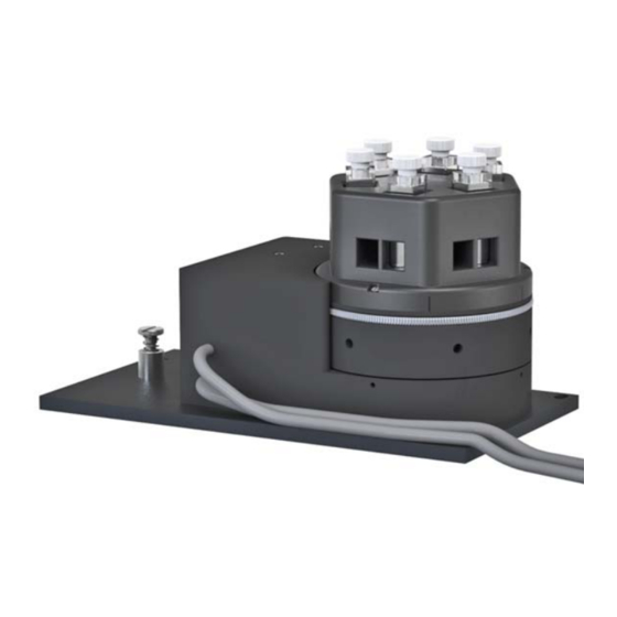
Set Position Set Position Target Current = 1 Set Position: To change the cuvette position, use the up and down arrows to choose the desired Target position and press . The controller will move the cuvette holder to the selected cuvette position, reflected by the value of Current. When the cuvette holder is powered on, the device homes to a starting point before seeking the targeted cuvette position. To manually home the device, push and hold the button for three seconds. This will home the cuvette holder before moving the device to the targeted position. 3. FEATURES OF THE TURRET 6 A. GENERAL DESCRIPTION The Turret 6 has a rotating, temperature‐controlled, cuvette tower which holds up to six cuvettes. The center of the tower is hollow, permitting light to pass into the entrance hole, through the tower, through a cuvette and exit the opposite side from the entrance. A plastic cover encloses the cuvette tower, providing thermal insulation. A floor is attached to the bottom of the cuvette tower, and the rotating body of the holder contains a Peltier element sandwiched between this floor and a brass heat exchanger. Water is put through the heat exchanger to draw off heat generated when the temperate is lowered. Figure 1. Turret 6 A miniature stepping motor is placed under each cuvette to drive rotating magnet and these six motors rotate with the Turret body. Dry gas may be directed next to the cuvette windows, both on the inside and the outside surfaces, to minimize condensation when working below the dew point 8 ... -
Page 9: Cuvette Holder
Figure 2. Back of the Turret 6 Two wires exit the stepping motor housing, one conducts the drive currents for the stepping motor and Peltier unit. The other conducts the more sensible sensor lines. The two brass 1/8‐inch hose barbs for water provide access to the heat exchanger. A 1/8‐inch stainless hose barb is used for the dry gas. The hoses to these connections and the power and sensor cable must be brought out of the sample compartment by a means that does not interfere with the spectroscopic measurement. Access for these utilities may need to be light tight. CAUTION: Accidently attaching a water line to the dry gas barb will severely damage the instrument! Attach the lines with care. B. CUVETTE HOLDER The Turret 6 holds standard 10 x 10 mm cuvettes with outside dimensions of 12.5 x 12.5 mm. A metal clip is used to push each cuvette into one of the corners of its individual space for reproducible positioning and to favor temperature transfer. Walls of the Turret body are relieved to prevent scratching of the optical surfaces of the cuvette. Cuvettes should be 45 mm or taller, otherwise they will be difficult to recover from the cuvette holders. C. CUVETTE Z‐HEIGHT The “z height” of a cuvette is the distance between the bottom surface of the cuvette and the designed position for the optical center line, where the incident beam of light strikes the cuvette. Turret The z height for cuvettes in the is 15 mm. 9 ... -
Page 10: Cooling Water For The Peltier
The Peltier element (or “thermoelectric cooler”) is a heat pump. When cooling, it transfers heat from the Turret body to a heat exchanger; when heating, electrical polarity is reversed and it transfers heat from the heat exchanger to the tower. When cooling, it is particularly important to transfer this heat away from the Peltier. This is accomplished with flowing water through the heat exchanger. A source of water (or other cooling fluid) must be connected to the ⅛‐inch hose barbs on the back of the Turret 6. If you purchase the BATH 10 from us, you will get an inexpensive submersible aquarium pump, the appropriate fittings for connecting tubing, and a plastic bucket. Connect the pump to the Turret 6, place it in the bucket with water, and run a return tube to the bucket. A more robust pump is available as the BATH 100 for a higher price, although the larger pump has a higher Wattage and tends to heat the water when used for extended periods of time. You may also provide the cooling water from another source, such as a refrigerated cooling bath or even a tap for brief use. You will need a flow of 100 ‐ 300 ml/minute. This flow should require a pressure of about 3 ‐ 5 psi (0.2 ‐ 0.3 bar). Do not exceed an input water pressure of 25 psi (1.7 bar), as damage may occur inside the Turret 6. The heat exchanger and hose barbs are brass, and the tubing inside the Turret 6 is vinyl. Be sure that any circulating fluid used, other than water, will not corrode these materials. The temperature of the heat exchanger in the Turret 6 is monitored using a thermistor. If the temperature exceeds 60 °C, then temperature control is shut down to prevent damage to the Peltier element and the warning, “check coolant flow,” displayed on the TC 1 temperature controller. This will happen if the circulating fluid gets too warm and/or is restricted in flow. The heat exchanger temperature may be accessed by computer through the RS 232 or USB connections on the back of the TC 1 Temperature Controller (see External computer control below). Temperature increases will be faster when room temperature water is used in the circulator. Temperature decreases will be faster when ice water is used. Only water should be circulated using the BATH 10. When using a refrigerated bath, circulating pre‐cooled fluids (such as 30% methanol or diluted ethylene glycol) at below 0 °C will permit measurements below the specified temperature range. 10 ... -
Page 11: Dry Gas To Minimize Condensation
F. DRY GAS TO MINIMIZE CONDENSATION Dry gas flows into the Turret 6 via the stainless 1/8‐inch hose barb on the rear side. The gas passes through small channels in the base of the Turret body, to partially equilibrate in temperature, before passing up through small holes on both the inside and outside cuvette surfaces. A flow of dry gas to prevent condensation is necessary any time the Turret 6 is controlled below the dew point temperature present on the inside of the sample compartment of the spectrometer. For ambient air, this would typically be about 5 °C. G. EXTERNAL TEMPERATURE PROBE A ¼‐inch phone jack labeled “Probe” can be found on the back panel of TC 1 Temperature Controller. This jack will accept the plug on a standard Series 400 or Series 500 thermistor probe. When a probe is plugged into the jack, the probe temperature is presented on the display of the TC 1. Place the probe in a sample to measure the actual temperature of the sample, which will lag in time from the temperature of the cuvette tower. We do not sell the probe, but there are many Series 400 and 500 probes on the market. Quantum Northwest’s preferred probe is the YSI 423 available from Cole Parmer. The YSI 423 is reasonably resistant to immersion and responds rapidly to temperature changes. Also, the fine, coiled wires of the YSI 423 conduct very little ambient heat to the thermistor at the end. Excellent Series 500 probes can be obtained with diameters less than a mm, providing access to small volumes. A disadvantage of these probes is that they are not pre‐calibrated. H. EXTERNAL COMPUTER CONTROL All functions may be accessed either through a Serial (RS 232) or a USB located on the back of TC 1 Temperature Controller. You may write your own program or purchase our application program T‐ App. T‐App will plot temperatures of the probe, cuvette tower or even the Peltier element heat exchanger vs time. It will also permit you to set up temperature ramps. If you wish to do your own programming, please see the Appendix for communication instructions and the set of text commands that may be used and responses to the commands. 4. ERROR CODES When errors occur, the line 1 of the display presents an error code. Line 3 of the display identifies the error and line 4 of the display presents possible solutions. The most common events that cause errors to be displayed are loose cables or inadequate coolant flow. For errors not easily solved, please contact us through our website, www.qnw.com. E5– cell out of range warnings: loose cable, sensor failure The temperature controller is not receiving a reasonable response from the sensor on the cuvette ... -
Page 12: E6 - Cell Out Of Range
E6 – cell out of range warnings: loose cable, check cable The temperature controller is not receiving reasonable responses from either the cell tower or heat exchanger sensors. Since it is very unlikely for both to fail, probably a cable is loose. E7 – heat exchanger error warnings: loose cable, sensor failure The temperature controller is not receiving a reasonable response from the sensor on the heat exchanger. Either the sensor has failed or a cable is not making a good connection. E8 – inadequate coolant warnings: inadequate coolant, water temperature The sensor on the heat exchanger is reading a temperature above 60 °C. Temperature control has been shut down to prevent damage to the Peltier element. Either the water was too warm or the rate of flow was inadequate to draw sufficient heat from the heat exchanger. 12 ... -
Page 13: Turret 6 Specifications
5. Turret 6 SPECIFICATIONS temperature range ‐20 to +110 °C temperature precision ±0.05 °C cuvette size (outside dimensions) 12.5 x 12.5 mm minimum cuvette height 30 mm magnetic stirring speed 0 to 1700 rpm cuvette z height 8.5 or 15 mm (specified when ordering) optical port dimensions (mask) 10 mm high x 8 mm wide 13 ... - Page 14 TC 1/t2 – for the t2, single temperature controller TC 1/t2x2 – for the t2x2, dual temperature controller for sample and reference TC 1/Turret 6 – for the Turret 6, 6‐position turret The version number and the ID (see below) are shown briefly on the display when the temperature controller is turned on. All functions of the temperature controller can be managed from a computer, using the command set described below. If you purchased your unit as a component of a spectrometer from certain manufacturers, this feature may be implemented through traditional RS232 serial connectors on the computer or the spectrometer and on the controller. In this case they will be connected by a standard 15‐pin serial extension cable (male connector on one end and female on the other). No driver installation should be needed. Otherwise the serial linkage will be established through a USB connection between the computer and the controller. In this case the controller includes electronics which convert the USB connection to a serial communications port. However, for the port to be available to programs on the computer it will be necessary to load driver software. It is important that the driver software be loaded before connecting a USB cable between the controller and the computer. Contact Quantum Northwest for further information. Quantum Northwest can provide a control program written specifically for control of all functions of the temperature controller. Ask for program T‐App. In programming for the TC 1 controller, one must adhere to the conventional notation: 8/N/1. Baud: 19200 Data Bits: 8 Parity: None Stop Bit: ...
- Page 15 [F1 ID ?] What is the ID number of the sample holder being controlled? ..[F1 ID 14] Sample holder is a t2 or other single cuvette sample holder. Assigned Identities: ID = 00 – specialty sample holder (see command class 14) 14 ‐ t2 24 ‐ t2x2 34 – reserved for turret or linear multi‐sample holder 2. Controller Firmware Version [F1 VN ?] What is the version number of the controller firmware? ..[F1 VN 1.00] The controller is operating firmware version number 1.00. ...
- Page 16 [F1 MT ?] What is the maximum target temperature allowed? ..[F1 MT 110] The maximum target temperature allowed is 110 ºC. [F1 LT ?] What is the lowest target temperature allowed? ..[F1 LT -30] The lowest target temperature allowed is ‐30 ºC. 6. Instrument Status [F1 IS ?] What is the current instrument status? ...
- Page 17 9. Probe Status and Temperature [F1 PS ?] Is there an external temperature probe connected? ..[F1 PR +] A probe is connected. ..[F1 PR -] No probe is connected. [F1 PS +] Enable probe status to be sent automatically when a probe is installed or removed. This is the default. [F1 PS -] Disable automatic sending of probe status. [F1 PT ?] What is the current probe temperature? [F1 PT +3] Periodically report the probe temperature every 3 seconds. ..[F1 PT 22.3] The current probe temperature is 22.3 degrees. ..[F1 PT NA] Probe temperature is not available. [F1 PT -] Stop periodic probe temperature reports. ...
- Page 18 2. set the ramp rate, 3. set a new target temperature (command class 5). The target temperature may be above or below the current temperature; as soon as it is set, the ramp will begin, up or down, to that new target. After reaching the target, the controller will hold at that temperature. At any time a new ramp rate and target temperature can be set to start a new ramp. Once you are done, set the ramp rate to 0. Otherwise, setting a new target temperature later will initiate a ramp to that target temperature. Notes: The minimum settable ramp rate is 0.01 °C/minute. For higher ramp settings, the observed rate may be lower than that calculated from RT and RS or it may be nonlinear over part of the temperature range because the maximum possible rate of heating or cooling is limited (and dependent on the ramp direction as well as on the temperature). When the ramping process is completed the controller will send a response of the form [F1 TT #] as a notification of the end of the ramp. This response can be blocked at any time by previously sending the command [F1 TT ‐] (see command class 5). 11. Heat Exchanger Temperature [F1 HL ?] What is the high temperature limit for the heat exchanger? ..[F1 HT 60] ...
- Page 19 [F2 PL 4] Device locate: move to position 4 and reply when done. (Device should be initialized prior to using this command for the first time.) ..[F2 DL 4] Device is now in position 4. [F2 DD 400] Set speed to 400 (acceptable range 100 – 900, with a default of 500). 13. Reference Cuvette These commands will have an effect only for systems with two independently‐controlled sample holders. [R1 ...] To control and monitor the temperature and status of the reference cuvette using a Dual ...
- Page 20 [R1 TT R-] Stop reporting manual changes for the reference target temperature. [R1 RR R-] Stop reporting manual changes for the reference ramp 20 ...
Need help?
Do you have a question about the Turret 6 and is the answer not in the manual?
Questions and answers