Table of Contents
Advertisement
Quick Links
turret 6/FO
6‐Position Temperature‐Controlled Cuvette Turret for
Fiber Optic Spectroscopy
Manual & Product Overview
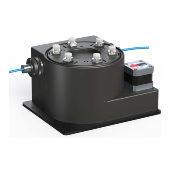
turret 6
Cuvette Holder
TC 1 Temperature
Controller
22910 East Appleway Avenue, Suite 4, Liberty Lake, WA 99019‐8606
Tel: (509) 624‐9290 • Fax: (509) 624‐9488 • E‐mail: quantum@qnw.com • Web: www.qnw.com
Advertisement
Table of Contents

Subscribe to Our Youtube Channel
Related Manuals for Quantum turret 6/FO


Summary of Contents for Quantum turret 6/FO
- Page 1 turret 6/FO 6‐Position Temperature‐Controlled Cuvette Turret for Fiber Optic Spectroscopy Manual & Product Overview turret 6 Cuvette Holder TC 1 Temperature Controller 22910 East Appleway Avenue, Suite 4, Liberty Lake, WA 99019‐8606 Tel: (509) 624‐9290 • Fax: (509) 624‐9488 • E‐mail: quantum@qnw.com • Web: www.qnw.com ...
-
Page 2: Table Of Contents
TABLE OF CONTENTS 1. Getting Started ............................ 3 A. Your Shipment Will Contain: ...................... 3 B. System Setup .......................... 4 C. Lens System Installation ......................... 4 D. Software Installation ........................ 7 E. System Operation ........................... 7 F. Using the Menu Button ........................ 8 2. Features of the turret 6 ........................ 10 A. General Description........................ 10 B. Cuvettes ............................ 11 C. Cuvette z‐Height ........................... 11 D. Cooling Water for the Peltier ....................... 11 E. Dry Gas Purging ........................... 12 F. External Temperature Probe ...................... 12 G. External Computer Control ...................... 12 H. Description of Lens Systems ...................... 12 3. Error Codes ............................ 14 4. Specifications Summary ........................ 15 Appendix 1. Temperature Specifications for the turret 6 .............. 16 Appendix 2. Serial Communications for the TC 1 Temperature Controller .......... 19 2 ... -
Page 3: Getting Started
1. GETTING STARTED Thank you for purchasing a Quantum Northwest turret 6/FO! We want you to enjoy many years of faithful service from your instrument. If you have any questions, feel free to contact us directly through our web site: www.qnw.com. A copy of this manual can be found on the site under the SUPPORT tab. A. Your Shipment Will Contain: turret 6 package turret 6 Temperature‐Controlled Cuvette Holder 2. TC 1 Temperature Controller 3. BATH 10 Submersible Pump and Bucket 4. power cable 5. USB cable turret 6 accessory kit (slits, wrench, blanks, and 6 magnetic stir bars) 7. vinyl tubing to connect water and gas Depending on Your Order, Your Shipment May Contain: Lens Systems 1. two t6‐QCL Collimating Lens for absorbance measurements 2. t6‐QIL/ex Imaging Lens for Excitation 3. t6‐QIL/em Imaging Lens for Emitted Light 4. t6‐QMP Mirror Plug 5. Plastic cap for covering unused ports ... -
Page 4: System Setup
B. System Setup 1. Place the turret 6 on a table. For stability you may wish to use screws to attach the turret 6, using the holes in the edge of the base. 2. Plug the power cable into the back of the TC 1 Temperature Controller and into a wall socket. (The TC 1 will accept AC voltages from 85 to 264 at 50 or 60 Hz.) 3. Supply circulating water to the Peltier unit. If you choose to use the BATH 10, then attach 1/8‐inch ID tubing from the submersible pump to either one of the water hose barbs on the turret 6. Attach another piece of tubing from the turret 6 back to the bucket. Direction of flow is not important. Put water in the bucket. Plug the pump’s circular DIN connector into the 12 Volt outlet on the back of the TC 1 labeled “IO.” Briefly turn on the TC 1 and check to be sure that water is flowing back into the bucket. Check for leaks. 4. If you plan to work at low temperatures, connect a source of dry gas (typically nitrogen) to release on the cuvette windows. Attach a length of tubing with 1/16‐inch inside diameter, to the small hose barb on the base of the turret 6. (A 1/8 to 1/16‐inch barbed reducer fitting is included with the turret 6, to prevent any difficulty connecting to this unusually small size tubing.) Set the dry gas flow rate to about 50 cc/min. has two electrical cables, one for drive currents and the other for 5. The turret 6 sensitive sensor signals. Connect them to the back of the TC 1 Temperature Controller on the 15‐pin connectors labeled “Sample” and “Reference”. 6. - Page 5 Figure 1. Absorbance configuration with collimating lenses on each side of the cuvette As shown in Figure 1, to set the turret 6 up for absorbance measurements insert collimating lens (QCL/t6) at positions 1 and 3 and screw into place. Put a black plastic cap from the turret 6 accessory kit in position 2. The collimating optics produce a 5 mm diameter beam that passes through the cuvette centered at 8.5 mm above the outside bottom surface. Attach fiber optics as describe below. Typically, light is passed from position 1 through the optical slit and cuvette and collected at position 3. If the slit is not being used, direction is not important. Figure 2. Fluorescence configuration with excitation and emission through imaging lenses and a mirror to reflect the incident light back on itself 5 ...
- Page 6 As shown in Figure 2, to set the turret 6 up for fluorescence measurements insert the imaging lens for excitation (t6‐QIL/ex) into position 1. This lens accepts the light from a fiber using a numerical aperture of 0.22 and focuses an image of the end of the fiber into the center of the cuvette using a magnification of 2.7. Insert the imaging lens for emission (t6‐QIL/em) in position 2. This lens images the center of the cuvette onto the end of the collection fiber using a magnification of 1.0. To enhance collection efficiency, a spherical mirror (60 mm radius of curvature) may be placed in position 3 to reflect the excitation source back on itself. Figure 3 ‐ Components of a lens assembly 1. Use the 5/64‐inch hex screwdriver from the turret 6 accessory kit to loosen the set screw (Figure 3). 2. Remove the silver sleeve with a black end piece from the lens assembly. Set it aside. 3. Screw the empty optical assembly all the way into the appropriate position in the turret 6. 4. Look for the location of the set screw. If it is in a difficult position to reach, remove the three fiber steering screws, rotate the end of the optical assembly until the set screw is accessible, and reattach the alignment assembly so the screw is more available. The steering screws compress an O‐ring, permitting fine alignment of the end of the fiber relative to the lens. Figure 4 ‐ Attaching the fiber optic to the SMA connector 6 ...
-
Page 7: Software Installation
5. Now, unscrew the silver sleeve from the black end piece revealing the SMA connector (Figure 4). 6. Slide the silver sleeve over the end of the fiber optic connector and cable, leaving the threaded end toward the end of the cable. 7. Attach the fiber optic cable to the SMA connector. 8. Holding the black end piece, screw the silver sleeve back into place. 9. Insert the SMA connector and silver sleeve into the hole in the optical assembly. For a first adjustment, insert the assembly until the alignment groove is even with the face of the lens assembly. Later, you can optimize the signal intensity by sliding the SMA connector and silver sleeve in deeper. D. Software Installation NOTE: IF YOU PURCHASED THE T‐App PROGRAM, DO NOT PLUG IN THE USB CABLE UNTIL THE SOFTWARE IS LOADED! IF YOU DO, WINDOWS MAY AUTOMATICALLY INSTALL AN INCORRECT DRIVER THAT WILL BE DIFFICULT TO REMOVE. 1. If you purchased the T‐App program for external control of the turret 6, insert the CD into the drive. If the installation does not start automatically, locate the SETUP.exe file in the root directory and run it. The installation process starts with a small black window that is shown during installation of the drivers needed to control the turret 6 through a USB connection. This window will then be replaced by the software installation window. Follow the onscreen prompts to complete the installation. 2. Connect the turret 6 to your computer using the USB cable provided. The New Hardware installation process will begin automatically and take a few moments to finish. E. System Operation 1. Use liquid samples in standard 1 x 1‐cm square cuvettes and place the cuvettes in the turret 6. ... -
Page 8: Using The Menu Button
Menu Button Start 5. The controller display begins on the page. Use the left or right arrows on the Menu Set Position Button to cycle through the five pages of options. On the page use the top and bottom arrows to choose a position, say position 5. Press set and the turret will rotate to Start Set this position and the menu will return to the page. To set a temperature, go to the Temperature page and use the up and down arrows to set a target temperature, say 37.0 SET °C. Press to initiate temperature control. The temperature will rise and stabilize. The Set Stirrer menu will then advance to the page. Use the up and down arrows to set a speed, SET say 1200 rpm, and press to start the stirrer. Start SET 6. When temperature control is running and the page is being displayed, press to turn off temperature control. 7. After measurements are completed, turn off power on the back of the TC 1 controller and turn off the water source. ... - Page 9 Set Position Position = 5 Current Position = 1 Set Position: To rotate the turret 6, use the up and down arrows to choose the new position and Display press . The controller will return to the page. Set Temperature Target = 37.0 °C Current= 20.0 °C Set Temperature: SET To set the Target temperature, use the up and down arrows. Press to retain this new Target and initiate temperature control. Set Stirring Stir Speed = 1200rpm Current = 0rpm Set Stirring: ...
-
Page 10: Features Of The Turret 6
2. FEATURES OF THE turret 6 A. General Description The turret 6 has a rotating, temperature‐controlled, metal cuvette tower which holds up to six cuvettes. An insulating cover of urethane plastic encloses the cuvette tower, providing thermal insulation. A floor is attached to the bottom of the tower, and the rotating body of the holder contains a Peltier element sandwiched between this floor and a brass heat exchanger. Water flows through the heat exchanger to draw off heat generated when the temperate of the cuvette tower is lowered. Figure 5. turret 6 with a section cut away to show the optic access to one of the cuvettes A miniature stepping motor resides under each cuvette to drive rotating magnet. Dry gas enters a 1/16‐inch hose barb on the front of the instrument and is carried through a manifold in the floor of the turret to small holes on the bottom of the 18 cuvette windows. This flow of gas will keep the windows free of condensation when working below the dew point temperature. The rotating body is mounted on a large precision bearing and rotated via gears, using the external Vexta stepping motor (not visible in this view). Two wires exit below the Vexta stepping motor. One conducts the drive currents for the stepping motor and Peltier unit. The other conducts the sensor lines. The two brass 1/8‐inch hose barbs for water provide access to the heat exchanger. A 1/16‐inch brass hose barb is used for the dry gas. CAUTION: Accidently attaching a water line to the dry gas barb will severely damage the instrument! Attach the lines with care. 10 ... -
Page 11: Cuvettes
B. Cuvettes The turret 6 holds standard 10 x 10 mm cuvettes with outside dimensions of 12.5 x 12.5 mm. A metal clip is used to push each cuvette into one of the corners of its individual space for reproducible positioning and to favor temperature transfer. Walls of the turret body are relieved to prevent scratching of the optical surfaces of the cuvette. Cuvettes should be 45 mm or taller, otherwise they will be difficult to recover from the cuvette holders. C. Cuvette z‐Height The “z height” of a cuvette is the distance between the bottom surface of the cuvette and the designed position for the optical center line, where the incident beam of light strikes the cuvette. turret The z height for cuvettes in the is 15 mm. Figure 6. The z height of a typical microcuvette D. Cooling Water for the Peltier The Peltier element (or “thermoelectric cooler”) is a heat pump. When cooling, it transfers heat from the turret body to a heat exchanger; when heating, electrical polarity is reversed and it transfers heat from the heat exchanger to the tower. When cooling, it is particularly important to transfer this heat away from the Peltier. This is accomplished with flowing water through the heat exchanger. A source of water (or other cooling fluid) must be connected to the ⅛‐inch hose barbs on the front of the turret 6. This can be done with the BATH 10, which is provide with the turret 6. The BATH 10 consists of a submersible aquarium pump, the appropriate fittings for connecting tubing, and a plastic bucket. Connect the pump to the turret 6, place it in the bucket with water, and run a return tube to the bucket. You may also provide the cooling water from another source, such as a refrigerated cooling bath or even a tap for brief use. You will need a flow rate of 100 ‐ 300 ml/minute. This flow should require a pressure of about 3 ‐ 5 psi (0.2 ‐ 0.3 bar). Do not exceed an input water pressure of 25 psi (1.7 bar), as damage may occur ... -
Page 12: Dry Gas Purging
Temperature increases will be faster when room temperature water is used in the circulator. Temperature decreases will be faster when ice water is used. Only water should be circulated using the BATH 10. When using a refrigerated bath, circulating pre‐cooled fluids (such as 30% methanol or diluted ethylene glycol) at below 0 °C will permit measurements below the specified temperature range. E. Dry Gas Purging Dry gas flows into the turret 6 via the 1/16‐inch brass hose barb on the rear side. The gas passes through small channels in the base of the turret body, to partially equilibrate in temperature, before passing up through small holes on both the inside and outside cuvette surfaces. A flow of dry gas to prevent condensation is necessary any time the turret 6 is controlled below the dew point temperature present on the inside of the sample compartment of the spectrometer. For ambient air, this would typically be about 5 °C. F. External Temperature Probe A ¼‐inch phone jack labeled “Probe” can be found on the back panel of TC 1 Temperature Controller. This jack will accept the plug on a standard Series 400 or Series 500 thermistor probe. When a probe is plugged into the jack, the probe temperature is presented on the display of the TC 1. Place the probe in a sample to measure the actual temperature of the sample, which will lag in time from the temperature of the cuvette tower. We do not sell the probe, but there are many Series 400 and 500 probes on the market. Quantum Northwest’s preferred probe is the YSI 423 available from Cole Parmer. The YSI 423 is reasonably resistant to immersion and responds rapidly to temperature changes. Also, the fine, coiled wires of the YSI 423 conduct very little ambient heat to the thermistor at the end. Excellent Series 500 probes can be obtained with diameters less than a mm, providing access to small volumes. A disadvantage of these probes is that they are not pre‐calibrated. G. External Computer Control All functions may be accessed either through a Serial (RS 232) or a USB located on the back of TC 1 Temperature Controller. You may write your own program or purchase our application program T‐ App. T‐App will plot temperatures of the probe, cuvette tower or even the Peltier element heat exchanger vs time. It will also permit you to set up temperature ramps. If you wish to do your own programming, please see the Appendix for communication instructions and the set of text commands that may be used and responses to the commands. H. Description of Lens Systems The t6‐QCL collimating lens is a 6 mm diameter, 18 mm focal length, fused silica lens that collects light from the source fiber at a numerical aperture of 0.22 and focuses a 5 mm diameter collimated ... - Page 13 beam through the cuvette at a z height of 15 mm. A second t6‐QCL reverses the process and focuses the collimated light onto a collection fiber. There are two kinds of imaging lens systems. Each contains a pair 12.5 mm diameter, 30 mm focal length, plano‐convex, fused silica lenses with their flat sides outward. The excitation lens (t6‐QIL/ex) focuses an image of the end of the source fiber into the middle of the cuvette with a magnification of 2.7. The emission lens (t6‐QIL/em) focuses a small region of the illuminated volume in the center of the cuvette onto the end of the emission collection fiber using a magnification of 1.0. The magnification of the excitation lens represents a compromise required to back the lens away from the cuvette to permit the rotation of the turret. If high fluorescence sensitivity is required, we recommend a more direct coupling of the source with the cuvette, bypassing the excitation fiber. Figure 7. Broadband anti‐reflection (AR) coating used on the standard fused silica lenses. Wavelength 13 ...
-
Page 14: Error Codes
3. ERROR CODES When errors occur, the line 1 of the display presents an error code. Line 3 of the display identifies the error and line 4 of the display presents possible solutions. The most common events that cause errors to be displayed are loose cables or inadequate coolant flow. For errors not easily solved, please contact us through our website, www.qnw.com. E5– cell out of range warnings: loose cable, sensor failure The temperature controller is not receiving a reasonable response from the sensor on the cuvette tower. Either the sensor has failed or a cable is not making a good connection. E6 – cell out of range warnings: loose cable, check cable The temperature controller is not receiving reasonable responses from either the cell tower or heat exchanger sensors. Since it is very unlikely for both to fail, probably a cable is loose. E7 – heat exchanger error warnings: loose cable, sensor failure The temperature controller is not receiving a reasonable response from the sensor on the heat exchanger. Either the sensor has failed or a cable is not making a good connection. E8 – inadequate coolant warnings: inadequate coolant, water temperature The sensor on the heat exchanger is reading a temperature above 60 °C. Temperature control has been shut down to prevent damage to the Peltier element. Either the water was too warm or the rate of flow was inadequate to draw sufficient heat from the heat exchanger. 14 ... -
Page 15: Specifications Summary
4. SPECIFICATIONS SUMMARY temperature range ‐20 to +110 °C temperature precision ±0.02 °C cuvette size (outside dimensions) 12.5 x 12.5 mm minimum cuvette height 30 mm cuvette z height 15 mm optical port dimensions 12 mm high x 10 mm wide magnetic stirring speed 1‐2500 rpm 15 ... -
Page 16: Appendix 1. Temperature Specifications For The Turret 6
APPENDIX 1. TEMPERATURE SPECIFICATIONS FOR THE TURRET 6 Enoch W. Small and Louis J. Libertini 26 July 2013 Temperature Range: ‐15 °C to + 80 °C The TC 1 Temperature Controller can set temperatures between ‐40 °C and 110 °C. Under normal conditions, as used inside a spectrophotometer, the turret 6 will achieve temperatures in the range of ‐15 °C and 80 °C using room temperature water (~22 °C). Somewhat lower temperatures can be obtained by the use of iced water. Temperatures above 80 can usually be attained by using warm water (recommended). In some cases higher temperatures may require operation without coolant flow, but special procedures are required. An input connection for purging with dry gas is provided. Temperature Precision: ± 0.02 °C Temperature precision is the average deviation from the set temperature of temperature readings returned from the temperature‐controlled turret 6 for set temperatures between ‐15 °C and + 110 °C. Thus, it is a measure of the ability of the cuvette holder to hold a constant temperature. The precision of the temperature actually held in the solution should be even better than the precision for the cuvette holder. Unfortunately, we have no current means of measuring it. Table 1. Average deviation from the set temperature vs set temperature for 50 points. Set temperature ‐15 0.0 20.0 40.0 60.0 80.0 100 110 Average deviation 0.0046 0.064 ... - Page 17 Figure 1. An NIST‐traceable RTD thermometer (accuracy ±0.03 °C from ‐99.9 °C to +99.9 °C) was inserted in the body of the cuvette holder and the temperature readings (y axis) compared to the value set by the TC 1 temperature controller (x axis). Data points shown as red squares are results were obtained with the temperature decreasing; the blue diamonds indicate results obtained with the temperature decreasing. Temperature Reproducibility: better than ± 0.15 °C over the range of 0 °C to 80 °C Temperature reproducibility is a measure of the ability of the temperature to return to an original value (See Figure 1.). It accounts for differences depending on the direction of temperature change and differences from day to day. Reproducibility is measured using a NIST‐traceable RTD temperature probe inserted in the metal block of the cuvette holder. Example of Temperature Performance time (min) Figure 2. turret 6 cuvette holder temperature and sample temperature (red, measured with a thermistor probe connected to the t2) as the target temperature setting was progressed through 20.0 °C, 50.0 °C, 0.0 °C, ‐15.0 °C, 80.0 °C and 20.0 °C degrees . 17 ...
- Page 18 Typical Temperature Equilibration Data A Turret was equilibrated at one temperature and then the target temperature was changed to a higher or lower value. Table 2. Time required for cuvette holder temperature changes. Three time are shown: the time required to get within 1 °C, the time to get within the lock on temperature of ±0.05 °C from the target and the final time indicating that the TC 1 indicates the temperature is stable. Temperature range (°C) 20 to 80 80 to 110 80 to 20 20 to ‐15 Circulating water T (°C/min) 21 none 21 Iced Minutes to get within 1 °C (min) 13 38 9.3 15 Minutes to lock on temperature (min) 16 42 13.3 20 Minutes to lock on indicator light (min) 18 54 18 25 18 ...
- Page 19 USB cable between the controller and the computer. Contact Quantum Northwest for further information. Quantum Northwest can provide a control program written specifically for control of all functions of the temperature controller. Ask for program T-App. In programming for the TC 1 controller, one must adhere to the conventional notation: 8/N/1.
- Page 20 Assigned Identities: ID = 00 – specialty sample holder (see command class 14) 14 ‐ t2 24 ‐ t2x2 34 – reserved for turret or linear multi‐sample holder 2. Controller Firmware Version [F1 VN ?] What is the version number of the controller firmware? ..[F1 VN 1.00] The controller is operating firmware version number 1.00. ...
- Page 21 6. Instrument Status [F1 IS ?] What is the current instrument status? ..[F1 IS 0-+S] Response is four parameters: number of unreported errors is 0 (0 to 9) stirrer is off (+ is on, ‐ is off) temperature control is on (+ is on, ‐ is off) ...
- Page 22 ..[F1 PR +] A probe is connected. ..[F1 PR -] No probe is connected. [F1 PS +] Enable probe status to be sent automatically when a probe is installed or removed. This is the default. [F1 PS -] Disable automatic sending of probe status. [F1 PT ?] What is the current probe temperature? [F1 PT +3] Periodically report the probe temperature every 3 seconds. ..[F1 PT 22.3] The current probe temperature is 22.3 degrees. ..[F1 PT NA] Probe temperature is not available. [F1 PT -] Stop periodic probe temperature reports. [F1 PA S 0.5] Set the increment for automatic reporting of the probe temperature ...
- Page 23 After reaching the target, the controller will hold at that temperature. At any time a new ramp rate and target temperature can be set to start a new ramp. Once you are done, set the ramp rate to 0. Otherwise, setting a new target temperature later will initiate a ramp to that target temperature. Notes: The minimum settable ramp rate is 0.01 °C/minute. For higher ramp settings, the observed rate may be lower than that calculated from RT and RS or it may be nonlinear over part of the temperature range because the maximum possible rate of heating or cooling is limited (and dependent on the ramp direction as well as on the temperature). When the ramping process is completed the controller will send a response of the form [F1 TT #] as a notification of the end of the ramp. This response can be blocked at any time by previously sending the command [F1 TT ‐] (see command class 5). 11. Heat Exchanger Temperature [F1 HL ?] What is the high temperature limit for the heat exchanger? ..[F1 HT 60] The heat exchanger high temperature limit is 60 ºC. [F1 HT ?] ...
- Page 24 [F2 DD 400] Set speed to 400 (acceptable range 100 – 500, with a default of 500). 13. Reference Cuvette These commands will have an effect only for systems with two independently‐controlled sample holders. [R1 ...] To control and monitor the temperature and status of the reference cuvette using a Dual Temperature Controller, use any commands in classes 3‐8, 10 and 11, substituting R1 for F1. There are no corresponding [R1 …] commands for command classes 1, 2, 9 and 12. If you wish to ramp the temperature of the reference and sample cuvettes together, please note the linking command, [F1 TL +], in command class 10. ...
Need help?
Do you have a question about the turret 6/FO and is the answer not in the manual?
Questions and answers