Sign In
Upload
Manuals
Brands
Teseq Manuals
Test Equipment
NSG 3040A-IEC
User Manuals: Teseq NSG 3040A-IEC Generator
Manuals and User Guides for Teseq NSG 3040A-IEC Generator. We have
1
Teseq NSG 3040A-IEC Generator manual available for free PDF download: Operation Manual
Teseq NSG 3040A-IEC Operation Manual (157 pages)
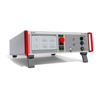
The ultra-compact simulator and its system modules
Brand:
Teseq
| Category:
Test Equipment
| Size: 11 MB
Table of Contents
Table of Contents
3
1 General
7
Purpose
8
Warranty Terms
9
Product Return Procedure
10
Recycling and Disposal
10
Rohs Directive 2011/65/EU (Rohs 2)
10
WEEE Directive 2012/19/EU
10
Dismantling Information
10
Parts Which Can be Recycled
10
Parts Which Cannot be Recycled
10
2 Safety Information
11
General
11
Connection to the Mains and PE
11
Disconnection from the Mains
11
Intended Use of the Equipment
11
Responsibility of the Operator
12
General Hazard
12
Safety Label on the Device
13
Prohibition of Unauthorized Conversions and Modifications
13
Specific Accessories Required for Safety Reason
13
Procedure in Case of Hazard
13
Temperatures at the Surface
13
3 Storage, Transport, Unpacking and Delivery Information
14
General
14
Storage and Transport
14
Unpacking
14
Lifting and Carrying Instructions
14
Scope of Delivery
15
Accessories
16
Options
16
4 Installation Put in Service
17
Safety Instructions for Installation and Initial Installation
17
Qualifications of the Staff
17
Installation
17
Installation of the NSG 3000A System
18
Installation Site
18
Voltage Free Switching
18
Grounding and Power Connection
18
Mains Switch and Fuse
19
Connecting the NSG 3040A / NSG 3060A System to the Ground Reference
19
Safety Circuit, Warning Lamps
20
Safety Circuit
21
Warning Lamp
21
EUT Power Supply and Power Switch
22
Notes on Protective Devices Which Need to Install the Operator
22
System Configuration
24
Power on the NSG 30X0A Generator
24
Software Number for Iec.control Software License
28
Software Update
29
Software Update New Version
29
Software Update Install Sysos
32
Export Actual Settings
34
Import the Settings
36
Manual Firmware Update
38
5 Design and Functions
40
Front View NSG 3040A and NSG 3060A
40
Rear View
42
Parameter Setting
44
Test Setting and Run Window
45
Set and Test Window
46
6 Menu
48
Test Phenomenon Menu to Start a Test
48
Menu for Settings
49
Manager
50
Information
50
EUT Setup
51
EUT Setup / TEST
52
EUT Setup / SUPPLY
52
Setup
54
Setup / System Menu
55
Setup / Date and Time Menu
55
Setup / Signals Menu
55
Setup / Display
56
Setup / Remote
56
Setup / Application / Process & Sync
57
Setup / Equipment / Devices & Modules
58
Setup / Equipment / External Couplers
59
Setup / Equipment / Transformers
60
Variable Voltage Transformers Adjustment Procedure
61
Adjustment Procedure for Variable Transformers
62
Adjustment Procedure for Tapped Transformers with Analogue DC Control Voltage
65
7 Test Equipment NSG 3040A and NSG 3060A Series
66
Nsg 3040A
66
Nsg 3060A
67
8 Technical Data
68
EFT Electrical Fast Transients Burst as Per IEC 61000-4-4
68
SURGE Immunity Requirements as Per IEC 61000-4-5
69
Technical Data Surge Module for NSG 3040A Series
69
Technical Data Surge Module for NSG 3060A Series
70
Pulsed Magnetic Field as Per IEC 61000-4-9
71
Power Fail Generator for DIPS, Interruption and Voltage Variation as Per IEC 61000-4-11
72
Power Magnetic Field as Per IEC 61000-4-8
73
Ring Wave Generator as Per IEC 61000-4-12
74
Telecom Surge Generator as Per IEC 61000-4-5 (T-Surge Module)
75
EUT Supply Specifications
76
General Specifications
76
Environmental Conditions
76
9 Maintenance Setup and Service
77
General
77
Maintenance and Cleaning
77
Test Setup
77
Insulating- or External Transformer for EUT Power Supply
77
Calibration and Verification
78
Factory Calibration
78
Guideline to Determine the Calibration Period of AMETEK CTS Instrumentation
78
Calibration of Accessories Made by Passive Components Only
78
Periodically In-House Verification
78
10 Delivery Groups
79
Basic Equipment
79
Accessories and Options
79
11 EFT Burst as Per IEC 61000-4-4
81
Operation
81
Burst Menu Options from Test Setting
82
Quick Start
83
Standard Test Routines
84
User Test Routines
85
STEP Routines
86
Burst Settings and Limits
87
Configuration
87
Max Burst Impulses / S
89
Burst Generation
90
Test Voltage with Burst as Per IEC 61000-4-4
90
Coupling/Decoupling Network
91
Coupling/Decoupling Network for Ac/DC Power Lines
91
Capacitive Coupling Clamp
91
Burst Test Setup
92
Test Setup with Capacitive Coupling Clamp
93
12 Surge Immunity as Per IEC 61000-4-5
94
Operation
94
Quick Start
95
Standard Test Routine
96
User Test Routines
98
STEP Routines
99
Surge Pulse Settings
101
Configuration
101
HV-COM Capacitance (18 Μf Capacitor)
103
Surge Pulse Application
104
Phase Synchronization in 3-Phase System
104
Surge Pulse Application
105
Coupling/Decoupling Network
105
Coupling to AC/DC Power Supply Lines
105
Coupling to I / O Lines
106
Test Setup
106
13 Magnetic Field Test as Per IEC 61000-4-9
107
Pulsed Magnetic Field Operation
107
Quick Start
109
Standard Test Routine
110
User Test Routines
111
14 Voltage Dips and Interruptions & Voltage Variation as Per IEC 61000-4-11
112
Test Setup for DIPS and Interruption Tests
112
Operation
114
Quick Start
115
Standard Test Routines
116
User Test Routines
117
Voltage Variation
118
The Power Fail Test
119
Test Routines Termination
119
Operating
119
Overcurrent
120
Voltage Drop over the PFS Switch
121
The Power Fail Test
122
Voltage Interruptions
122
Voltage Dips, Voltage Variations
123
The Power Fail Verification
124
Test Setup and Accessories
125
Transformer Type TVT 1-250-16
125
Variable Transformer Variable Transformer VAR 3005A-S16
127
15 Power Frequency Magnetic Field as Per IEC 61000-4-8
129
Operation
129
Quick Start
129
Required Device Setting to Perform a Power Frequency Magnetic Field Test
130
Test Setup for Power Frequency Magnetic Field Test
131
Test Setup with MFT 30 for H-Fields up to 30 A/M
131
Test Setup with MFT 100 for H-Fields up to 1.000 A/M
132
16 Telecom Surge Immunity as Per IEC 61000-4-5
133
Operation
133
Generator Network for Telecom Surge
134
Quick Start
135
Standard Test Routine
136
STEP Test Routines
137
Telecom Surge Pulse Settings
138
Configuration
138
17 Ring Wave Immunity as Per IEC 61000-4-12
139
Operation
139
Quick Start
140
Standard Test Routine
141
User Test Routines
143
STEP Routines
144
Ring Wave Pulse Settings
145
Configuration
145
Ring Wave Pulse Application
147
Phase Synchronization in 3-Phase System
147
Ring Wave Pulse Application
148
Coupling/Decoupling Network
148
Coupling to AC/DC Power Supply Lines
148
Coupling to I / O Lines
149
Test Setup
150
18 Appendix
151
Declaration of CE-Conformity
151
CE-Conformity NSG 3040A Series
151
CE-Conformity NSG 3060A Series
152
CE-Conformity Tapped Voltage Transformer TVT 1-250-16
153
CE-Conformity Tapped Voltage Transformer TVT 1-250-16.1
154
CE-Conformity CCI (Capacitive Coupling Clamp)
155
NSG 3040A Series General Block Diagram
156
NSG 3060A Series General Diagram
157
Advertisement
Advertisement
Related Products
Teseq NSG 3040A-EFT-CWS
Teseq NSG 3040A-EFT
Teseq NSG 3040A-CWS
Teseq NSG 3040A-DDV
Teseq NSG 3060A-IEC
Teseq NSG 3060A-FULL
Teseq NSG 3060A-EFT-CWS-RWG
Teseq NSG 3060A-EFT-CWS-TS
Teseq NSG 3060A-CWS-DDV
Teseq NSG 3060A-CWS-TS
Teseq Categories
Amplifier
Test Equipment
Switch
Portable Generator
Antenna
More Teseq Manuals
Login
Sign In
OR
Sign in with Facebook
Sign in with Google
Upload manual
Upload from disk
Upload from URL