Table of Contents
Troubleshooting

Related Manuals for SOFTLINK WB169-430-V


Summary of Contents for SOFTLINK WB169-430-V
- Page 1 WIRELESS COMMUNICATION SYSTEM Wireless M-Bus WB169-430-V Revision 1.0 SOFTLINK s.r.o., Tomkova 409, 278 01 Kralupy nad Vltavou, Czech Republic Phone.: +420 315707111, e-mail: sales@softlink.cz, www.softlink.cz...
-
Page 2: Table Of Contents
..... . . Structure of Wireless M-BUS message header of the WB169-430-V module .... - Page 3 ......... View of WB169-430-V module information message received by WMBUSAN4 analyzer .
-
Page 4: Introduction
(AMR) in form of Wireless M-Bus radio-messages in 169 MHz frequency band (”INFO” messages). The WB169-430-V module can by used for remote reading up to 20 watermeters placed in its radio-reach (that is up to hundreds meters). Each watermeter transmits the messages with a short fixed period (e.g. iPERL every 15 seconds). -
Page 5: Hardware Features And Power Supplying
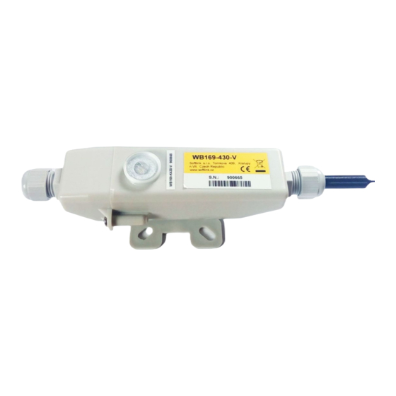
The module is equipped with the special circular aperture (”peephole”) for magnetic fixing of the optical converter. The module can be also configured remotely, with using of reverse channel of bi-directional communication. External appearance of the WB169-430-V module is shown in the figure 1. Figure 1: View of the WB169-430-V module WB169-430-V... -
Page 6: Technical Parameters Overview
Technical parameters overview Overview of WB169-430-V module technical parameters is shown in the Table1 below. Table 1: Overview of WB169-430-V module technical parameters RF subsystem parameters Frequency band * 169.40625 to 169.46875 Modulation * 2-GFSK, 4-GFSK Bandwidth * 12.5 or 50... -
Page 7: Configuration Of The Wb169-430-V Module
Setting of WB169-430-V module parameters by configuration cable In following part of the document there is a description of these parameters of the WB169-430-V module, that can be displayed and examined from PC connected to the module by configuration cable. Some of the parameters can be changed by configuration commands entered... - Page 8 : Set test on modem, 1 - TX carrier, 2 - TX PN9, time is in second, default 10 : Get modem state : Get modem info si2cap : Set or get xtal capacity correction si2xtal : Set or get xtal frequence cfreq2 : Set xtal from analyzer WB169-430-V...
-
Page 9: Commands For Writing Of Configuration And Reset
”mon#”. If operating configuration was ” changed so that it no longer matches to the saved set, the module will report prompt in the format ”cfg#”. WB169-430-V... -
Page 10: Commands Of
433 MHz modem internal registers (diagnostics) si1xtal 169 MHz modem frequency constant setting (factory setting) si1cap 169 MHz modem crystal correction (factory setting) cfreq1 169 MHz modem frequency constant correction (factory setting) Manufacturer strongly recommends not to use these commands during common operation. WB169-430-V... - Page 11 (regardless of the number of messages received from this meter), is filled. The result is a table of all water meters, from which at least one message was captured in the receiving window. The opening time of the receive window is set by the command parameter [time]. WB169-430-V...
- Page 12 - value ”5” for transmitting power 27 dBm (500 mW) An example of checking, setting and re-checking of transmitting power: cfg#power2 MBUS power : 3 (20 dBm) cfg#power2 5 MBUS power changed from 3 to 5 (27 dbm) cfg#power2 MBUS power : 5 (27 dBm) cfg# WB169-430-V...
-
Page 13: Commands For Setting Of Watermeter Reading
The ”Set Meter ID” variable serves for setting of list of watermeters, that is intended to be read by the WB169- 430-V module. Each record to the list could be created by using of ”sid [index] [value]” command, where meter ID (serial number) is linked with meter index (0 - 19). WB169-430-V... - Page 14 0 76738781 WMBUS ID[0] changed from : 0 to : 76738781 cfg# Current list of read watermeters is stated in the list of all configuration parameters. The list can be also displayed by using of ”sid” command without parameters: WB169-430-V...
- Page 15 WMBUS message by a pair of auxiliary codes DIF=02 and VIF=5B, where the individual codes mean: - DIF=02 means that the data in 16 bit integer format - VIF=5B means variable of ”Flow Temperature” type in whole C This is obviously the temperature of the water flowing through the watermeter. WB169-430-V...
- Page 16 [19] - Burst - 0, Leak - 0, Baterry - 0, Back flow - 0 cfg# The example shows a situation where statuses are read from four watermeters, the first two being of a different type than the second two. WB169-430-V...
-
Page 17: Commands Of " Utils" Group For Setting Of Module Basic Functions
Current setting of Time Zone displays in the configuration summary as follows: Timezone : 1 Current setting of RTC can be displayed by entering of ”time” or ”date” command (without parameter). Example: cfg#time RTC time : 15:30:17 2019-01-30 systime 1548858617 : 2019-01-30, 15:30:17+01 cfg# WB169-430-V... - Page 18 Medium”. This combination must be unambiguous that ” ” ” ” means there cannot exist two M-Bus devices worldwide. The WB169-430-V module has fixed values of M-BUS ID” ” Manufacturer” address components, that are displayed in the list of configuration parameters and cannot be ”...
- Page 19 By using of ”send” command the message can be transmitted immediately ( out od turn”). that can be ” used for example for checking of radio signal availability during the system installation. An example of immediate sending of Wireless M-Bus message by ”send” command: WB169-430-V...
-
Page 20: Displaying Of Other Operational Entries In The List Of Parameters
SW Version software version by manufacturer SW Revision software revision by manufacturer Manufacturer MBUS Manufacturer code All the parameters contain information about device identification, series and hardware/software version and are intended only for manufacturer’s use. WB169-430-V... -
Page 21: Wb169-430-V Module Configuration Table
”Medium” parameter is an international code of measured energy, water or other medium according to the M- Bus coding system. The value of the parameter is editable for the WB169-430-V, the default value is 07 (”Water”). More detailed description of the variable and possibilities of its setting are explained in details in section 3.1.7... - Page 22 ” The ”Sensus ID” is a list of Sensus iPERL watermeters, that are intended to be read by the WB169-430-V mod- ule. It contains 5 editable fields (index 1 - 5), where watermeter IDs (serial numbers) can be preset. Any received messages.
-
Page 23: Configuration Forms Of Wb169-430-V Module In Softlink Configurator" Application
Figure 3: Configuration forms of WB169-430-V module in SOFTLINK Configurator” application ” In the figure there is a description of procedure of entering of meters into the reading list in Sensus iPERL” ” mode (bordered by violet colour) and view of analogous setting for WMBUS”... -
Page 24: Remote Setting Of Module Parameters Through Reverse Channel
” channel”. Reverse channel can be used for setting of some module parameters from remote server. The WB169-430-V module is permanently working in bidirectional communication mode N2 and can receive Wireless M-Bus Request” messages from superior server. On the base of these messages the module can ”... -
Page 25: Overview Of Module Configuration Parameters
3.3.1 Overview of module configuration parameters Overview of configuration parameters that can be used for user settings of the WB169-430-V module is shown in the Table below. The parameters are presented in the same order as they appear in the List of all configuration parameters (see paragraph 3.1.1). -
Page 26: Structure Of Module Data Messages
”INFO” field). Structure of Wireless M-BUS message header of the WB169-430-V module is described in the Table 3. Table 3: Structure of Wireless M-BUS message header of the WB169-430-V module... -
Page 27: Alarm Message
32, 48, 64...etc. Bytes). Rounding of the message is performed by inserting of required number of ”2F” blocks. Decoded encrypted message of the WB169-430-V module with two control segments at the beginning and several other ”2F” blocks at the end is shown in the Figure 6. This way the length of message data block is rounded to 64 Byte. -
Page 28: Setting Messages
”configuration stored”). In the figure there is an example of decoded alarm message of the WB169-430-V module about the module reset with reset code ”0” ( Cold start”): As evident from the example, ”CI” bit in the message header is set to ”74”... -
Page 29: Table Of Variables In Setting Messages Of Wb169-430-V Module
Acknowledgment” message, which its superior communication gateway transmits to the central system. ” Request” message is always received by the WB169-430-V module in a dedicated time window of 500 ms after ” a regular ”User Data” (INFO) information message has been transmitted. During this time window, the module has the receiver switched on and is able to receive a possible Request”... -
Page 30: Structure Of Message With The Content Of " Sid" Table
Using the Radar” setting message it is possible to remotely find out which watermeters are in the radio range ” of given WB169-430-V module, or obtain a list of read watermeters of the module. Using the Water meter ID” ”... -
Page 31: Operational Conditions
Operational conditions This section of the document describes basic recommendations for transportation, storing, installation and operation of WB169-430-V radio modules. General Operation Risks The radio modules are electronic devices power-supplied by internal batteries. The modules read counters or registers of the connected consumption meters. -
Page 32: The Condition Of Modules On Delivery
(municipal) authority. WB169-430-V module installation WB169-430-V radio modules are enclosed in plastic casings with an IP65 degree of protection equipped with mounts for mounting on the wall, pipe or any other construction element. Battery switch, configuration connector as well as antenna connectors are placed on the module’s printed circuit board, so that it is necessary to open the casing... -
Page 33: Set Of Wb169-430-V Module Components With Rod Antenna
Figure 10: Set of WB169-430-V module components with rod antenna In the figure there is displayed the detail of WB169-430-V module printed circuit board with configuration connector marked by red colour, 169 MHz antenna connector marked by blue colour, 433 MHz antenna connector marked by light-blue colour and battery switch marked by yellow colour. - Page 34 The radio-signal conditions can be estimated empirically on the base of previous experience, or examined by measuring of the signal strength by the reference transmitter/receiver. WB169-430-V...
-
Page 35: Module And Meter Replacement
Put the module parts back together by mounting of the cap on the module base. After the dismantling mark the module as dismantled” and fill in the relevant documentation, prescribed for this ” situation by the internal rules. If possible, arrange deactivation of the module in the database of remote reading system immediately. WB169-430-V... -
Page 36: Functional Check Of The Module
(RSSI = Received Signal Strength Indicator) If the Radar” table is displayed in a sufficiently long time since the WB169-430-V module was putting into operation ” (or since its rebooting), the table should contain reports from meters and sensors connected to the module, including the evaluation of the receiving quality. -
Page 37: Troubleshooting
Troubleshooting Possible causes of module failures If during operation of WB169-430-V module some anomaly, malfunctions or other troubles are recognized, the possible causes of the failures can be classified by following categories: 5.1.1 Power supplying failures The module is supplied by electrical power from the long-life internal battery. -
Page 38: Failures Of Communication With Watermeters
To identify a reason of device failure or any anomaly in its operation follow this procedure: 1. No data are available from any watermeter read by the WB169-430-V module. In this case it is recommended to check functionality of the module subsystems in following order: check correctness of setting of the module in the central system database;... -
Page 39: Additional Information
ID and index in the table of read watermeters in the WB169-430-V module configu- ration; check functionality of receiving of messages from watermeters as described in paragraph 5.1.4...
Need help?
Do you have a question about the WB169-430-V and is the answer not in the manual?
Questions and answers