
Related Manuals for TELEDYNE OLDHAM SIMTRONICS iTRANS 2


Summary of Contents for TELEDYNE OLDHAM SIMTRONICS iTRANS 2
- Page 1 USER MANUAL iTRANS 2 FIXED POINT SINGLE OR DUAL GAS MONITOR WITH DUAL ANALOG OUTPUTS 77036429-EN-Revision 7.0...
- Page 2 User Manuals in other languages are available on Website https://teledynegasandflamedetection.com Copyright March 2021 by TELEDYNE OLDHAM SIMTRONICS S.A.S. All rights reserved. No reproduction of all or part of this document, in any form, is permitted without the written consent of TELEDYNE OLDHAM SIMTRONICS S.A.S.
- Page 3 2 FIXED POINT SINGLE OR DUAL GAS MONITOR WITH DUAL ANALOG OUTPUTS USER MANUAL Warnings and Cautionary Statements CAUTION: Failure to perform certain procedures or note certain conditions may impair the performance of the monitor. For maximum safety and performance, please read and follow the procedures and conditions outlined below.
- Page 4 6 months. Further, TELEDYNE OLDHAM SIMTRONICS recommends prudent testing and/or includes calibration after a gas alarm. All calibration service to sensors should be recorded and accessible.
-
Page 5: Table Of Contents
2 FIXED POINT SINGLE OR DUAL GAS MONITOR WITH DUAL ANALOG OUTPUTS USER MANUAL Table of Contents Overview ................... 1 Overview of the Gas Monitor............1 Specifications ...................... 1 Agency Approvals .................... 3 Hardware Overview ............... 5 Main Electronics Unit (Housing) ..............5 Sensor ........................ - Page 6 2 FIXED POINT SINGLE OR DUAL GAS MONITOR WITH DUAL ANALOG OUTPUTS USER MANUAL Introduction ......................35 Sample Gas Reading via ModBus Network ..........36 ModBus Register List ..................36 ModBus Resources .................... 39 Termination ......................39 Maintenance ................... 41 Introduction ......................
-
Page 7: Overview
2 FIXED POINT SINGLE OR DUAL GAS MONITOR WITH DUAL ANALOG OUTPUTS USER MANUAL Overview Overview of the Gas Monitor fixed gas monitor is an independent monitor capable of displaying one or two gas concentrations as well as sensor or instrument specific diagnostics. - Page 8 2 FIXED POINT SINGLE OR DUAL GAS MONITOR WITH DUAL ANALOG OUTPUTS USER MANUAL Item Description Input Voltage 12-28 VDC operating range (24 VDC typical) 150 mA@24 VDC (single gas) Toxic Gas/Oxygen 200 mA@24 VDC (single gas + HART) 250 mA@24 VDC, 0.8 A peak (single gas)
-
Page 9: Agency Approvals
2 FIXED POINT SINGLE OR DUAL GAS MONITOR WITH DUAL ANALOG OUTPUTS USER MANUAL Sensor Range/Resolution Combustible Gases 0 -100% LELin 1%increments Hydrogen 0 - 999 ppm in 1 ppmincrements Oxygen 0 - 30.0% by volin 0.1%increments Ammonia 0 - 500 ppmin 1 ppmincrements... - Page 10 • CSA Std C22.2 No.30-M1986-Explosion-Proof Enclosures for Use in Class I Hazardous Locations • CSA Std C22.2 No.142-M1987-Process Control Equipment • CSA Std C22.2 No. 152-M1984-Combustible Gas Detection Instruments (iTrans 2 with catalytic sensors only) • CSA Std C22.2 No. 213-M1987-Non-incendive Electrical Equipment for Use in Class I,...
-
Page 11: Hardware Overview
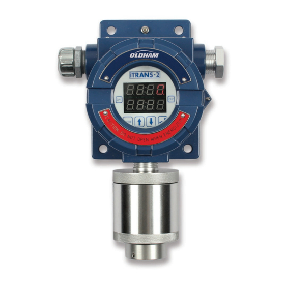
2 FIXED POINT SINGLE OR DUAL GAS MONITOR WITH DUAL ANALOG OUTPUTS USER MANUAL Hardware Overview Main Electronics Unit (Housing) body is a cast aluminum housing that contains the electronics of the gas monitor. Details of a single-gas housing are shown in Figure 2-1. -
Page 12: Sensor
2 FIXED POINT SINGLE OR DUAL GAS MONITOR WITH DUAL ANALOG OUTPUTS USER MANUAL Sensor Item Descriptions Aluminum, Anodized, Explosion-proof: Class I, Divisions 1 and 2, Groups B, C, D and Ex d IICT6 Gb (China) and Ex d IIB + H... -
Page 13: Electronics Modules
2 FIXED POINT SINGLE OR DUAL GAS MONITOR WITH DUAL ANALOG OUTPUTS USER MANUAL Figure 2-3. For applications that require non-intrusive manipulation, two magnetically-activated reed switches are used to accomplish programming without removing the cover. A magnetic wand is positioned over the appropriate reed switch (above the glass face plate) without the wand physically touching the reed switches. - Page 14 2 FIXED POINT SINGLE OR DUAL GAS MONITOR WITH DUAL ANALOG OUTPUTS USER MANUAL Figure 2-4 Electronics Module for (Main Unit) Figure 2-5 Electronics Board for Remote Sensor 77036429-EN Revision 7.0...
-
Page 15: Installation
2 FIXED POINT SINGLE OR DUAL GAS MONITOR WITH DUAL ANALOG OUTPUTS USER MANUAL Installation Introduction can be mounted in one of two ways. The unit can be wall-mounted using the wall mounting holes in the enclosure, or it can be mounted onto a column using U-bolts. Each of these options is discussed in this chapter. - Page 16 2 FIXED POINT SINGLE OR DUAL GAS MONITOR WITH DUAL ANALOG OUTPUTS USER MANUAL Figure 3-1 Mounting the Gas Monitor on a Wall Figure 3-2 Mounting the Gas Monitor on a Column Using U-Bolts 77036429-EN Revision 7.0...
-
Page 17: System Wiring
2 FIXED POINT SINGLE OR DUAL GAS MONITOR WITH DUAL ANALOG OUTPUTS USER MANUAL System Wiring Introduction This chapter outlines the steps required for wiring the gas monitor. These steps include the following: • Wiring Preparation • Sensor Wiring •... -
Page 18: Alarm Relay Wiring (J1, J5, And J6)
2 FIXED POINT SINGLE OR DUAL GAS MONITOR WITH DUAL ANALOG OUTPUTS USER MANUAL IMPORTANT: Use of this product in areas where it may be subject to large amounts of electromagnetic interference may affect the reliable operation of this device and should be avoided. -
Page 19: Power And Output Wiring (J1)
2 FIXED POINT SINGLE OR DUAL GAS MONITOR WITH DUAL ANALOG OUTPUTS USER MANUAL Power and Output Wiring (J1) Connect the power and signal wires to the appropriate wiring terminals as follows. • 24 V:Connect 24 VDC (12-28 VDC) supply power •... - Page 20 2 FIXED POINT SINGLE OR DUAL GAS MONITOR WITH DUAL ANALOG OUTPUTS USER MANUAL Figure 4-3 Sensor Connector J3 on the NOTE: For dual-sensor configurations, place both of the same colored wires in the appropriate terminal block and firmly tighten.
- Page 21 2 FIXED POINT SINGLE OR DUAL GAS MONITOR WITH DUAL ANALOG OUTPUTS USER MANUAL Figure 4-5 Wiring Diagram for a Remote Sensor (Stand Alone) NOTE: When the remote sensor is at distances of 200 meters or further, and the sensor is not communicating, the jumper J1 may need to be moved to terminals 1-2.
- Page 22 2 FIXED POINT SINGLE OR DUAL GAS MONITOR WITH DUAL ANALOG OUTPUTS USER MANUAL Figure 4-7 Wiring Remote Sensors Back to Figure 4-8 Wiring Dual Remote Sensors 77036429-EN Revision 7.0...
-
Page 23: Digital Modbus Rtu Interface Wiring (J1)
2 FIXED POINT SINGLE OR DUAL GAS MONITOR WITH DUAL ANALOG OUTPUTS USER MANUAL Digital ModBus RTU Interface Wiring (J1) 4.6.1 ModBus Interface Wiring Overview To interface the to a digital controller, PLC, or HMI, connect the power and ground to the appropriate terminals mentioned above. - Page 24 2 FIXED POINT SINGLE OR DUAL GAS MONITOR WITH DUAL ANALOG OUTPUTS USER MANUAL Figure 4-11 Setting the ModBus Address (Example Address of 240 Decimal) 4.6.3 Setting the ModBus Address for Stand-Alone Sensors NOTE: This section is only necessary if you are connecting a sensor directly to a ModBus controller, PLC, or digital system.
-
Page 25: Wiring Conclusion
2 FIXED POINT SINGLE OR DUAL GAS MONITOR WITH DUAL ANALOG OUTPUTS USER MANUAL Figure 4-13 Setting the ModBus Address for a Stand-Alone Sensor NOTE: If adding a second sensor to an existing module, set the ModBus address to ↑↑↑↑↓↓↓↓... - Page 26 2 FIXED POINT SINGLE OR DUAL GAS MONITOR WITH DUAL ANALOG OUTPUTS USER MANUAL 77036429-EN Revision 7.0...
-
Page 27: Operation
2 FIXED POINT SINGLE OR DUAL GAS MONITOR WITH DUAL ANALOG OUTPUTS USER MANUAL Operation Initial Start-up Once power is applied (12-28 VDC), the is operational. The LED display powers up, and the system enters a start-up period. During this start-up period, the identifies the sensors that are connected and then enters a three minute warm-up period. -
Page 28: Programming Mode Overview
2 FIXED POINT SINGLE OR DUAL GAS MONITOR WITH DUAL ANALOG OUTPUTS USER MANUAL As gas concentrations increase, the respective channel’s readings will respond accordingly. If low or high alarm levels are exceeded, an alarm indication will appear in the first digit of the display. -
Page 29: Programming Mode - Non-Intrusive Operation
2 FIXED POINT SINGLE OR DUAL GAS MONITOR WITH DUAL ANALOG OUTPUTS USER MANUAL When in the Programming Mode, either via the magnetic wand or keypad operation, the top line of the main display area shows a status bit and three data bits. The bottom line of the display shows the timers (see Figure 5-5). - Page 30 2 FIXED POINT SINGLE OR DUAL GAS MONITOR WITH DUAL ANALOG OUTPUTS USER MANUAL 5.5.2 Sensor Type To enter non-intrusive operation during the Normal Operating Mode, place the magnetic wand over the CH1 designation. The will display the sensor type for channel 1 for 5 seconds then enter in the Zero Menu.
- Page 31 2 FIXED POINT SINGLE OR DUAL GAS MONITOR WITH DUAL ANALOG OUTPUTS USER MANUAL 5.5.4 Calibration Calibration is the next available option. Calibration is designated with a “C” in the status bit. A 10 second timer is displayed on the bottom line of the LED display. To initiate calibration, place the magnetic wand over CH2 during the 10-second countdown.
- Page 32 2 FIXED POINT SINGLE OR DUAL GAS MONITOR WITH DUAL ANALOG OUTPUTS USER MANUAL 5.5.5 Changing Span Gas Concentration The option after calibration is Span Gas Concentration. The span option is designated with a flashing “S” in the status bit with the current span value next to it.
-
Page 33: Programming Mode - Push Button Operation
2 FIXED POINT SINGLE OR DUAL GAS MONITOR WITH DUAL ANALOG OUTPUTS USER MANUAL Programming Mode – Push Button Operation 5.6.1 Introduction In a safe environment where the windowed top of the transmitter can be removed, there are more programming options available. - Page 34 2 FIXED POINT SINGLE OR DUAL GAS MONITOR WITH DUAL ANALOG OUTPUTS USER MANUAL 5.6.3 Set Low Alarm The low alarm setpoint is designated with an “L” displayed in the status bit and current low alarm value displayed next to it.
- Page 35 2 FIXED POINT SINGLE OR DUAL GAS MONITOR WITH DUAL ANALOG OUTPUTS USER MANUAL If you do not press “↵” during the 10-second countdown, the will return to the Normal Operating Mode. If you initiate the 4-20 mA range option, the status bit will start to...
- Page 36 2 FIXED POINT SINGLE OR DUAL GAS MONITOR WITH DUAL ANALOG OUTPUTS USER MANUAL 5.6.8 Set System Time – Day The system’s day of the month setting is designated with a “d” in the status bit and current value next to it. To change the day, press the “↵”...
- Page 37 2 FIXED POINT SINGLE OR DUAL GAS MONITOR WITH DUAL ANALOG OUTPUTS USER MANUAL 5.6.11 Zeroing Zeroing is an option available both through the keypad and non-intrusively. A “0 ” is displayed in the status bit of the display to designate this function. A 10 second timer is displayed on the bottom line of the LED display.
- Page 38 2 FIXED POINT SINGLE OR DUAL GAS MONITOR WITH DUAL ANALOG OUTPUTS USER MANUAL NOTE: Flow rate for calibration is 0.5 liter per minute (LPM) except for NH , ClO , Cl , NO , and HCl which require 1.0 LPM.
- Page 39 2 FIXED POINT SINGLE OR DUAL GAS MONITOR WITH DUAL ANALOG OUTPUTS USER MANUAL 5.6.15 Last alarm – Day The day of last alarm is designated with an “2” in the status Figure 5-289 Day of last alarm bit. The day of last alarm is displayed on the top line of the Display LED display.
- Page 40 2 FIXED POINT SINGLE OR DUAL GAS MONITOR WITH DUAL ANALOG OUTPUTS USER MANUAL 5.6.18 Last calibration – Month The month of last calibration is designated with an “7” in the status bit. The mouth of last calibration is displayed on the top line of the LED display.
-
Page 41: Modbus Interface
Introduction IMPORTANT: The device with public Modbus interface can also be configured to operate with a MX43 controller from TELEDYNE OLDHAM SIMTRONICS. Please follow the procedure given below to enable MX43- compatibility mode on Set the Modbus ID of using dip-switches as shown in... -
Page 42: Sample Gas Reading Via Modbus Network
2 FIXED POINT SINGLE OR DUAL GAS MONITOR WITH DUAL ANALOG OUTPUTS USER MANUAL IMPORTANT: When commissioning master and slave units on a ModBus network, it is critical to ensure that every device on the ModBus network must have a unique address. Otherwise, abnormal behavior of the entire serial bus can occur. - Page 43 2 FIXED POINT SINGLE OR DUAL GAS MONITOR WITH DUAL ANALOG OUTPUTS USER MANUAL Inst Host Addr Range Description Chlorine Dioxide Hydrogen Cyanide Phosphine Hydrogen Carbon Dioxide Nitric Oxide Ammonia Hydrogen Chloride Oxygen Methane Lower Explosive Limit (Combustible Gases)
- Page 44 2 FIXED POINT SINGLE OR DUAL GAS MONITOR WITH DUAL ANALOG OUTPUTS USER MANUAL Inst Host Addr Range Description Dec 25 is represented as $0C19 June 31 is represented as $061F Last Alarm Date (00yy) Holds the last two digits of the year when the instrument was last in alarm. The first two digits are assumed to be “20”.
-
Page 45: Modbus Resources
“public” jumper that can be used to jumper in a 120-Ohm terminating resistor. By default, this jumper is not in place. TELEDYNE OLDHAM SIMTRONICS does not recommend changing the placement of any of the other jumpers on this board. - Page 46 2 FIXED POINT SINGLE OR DUAL GAS MONITOR WITH DUAL ANALOG OUTPUTS USER MANUAL 77036429-EN Revision 7.0...
-
Page 47: Maintenance
Infrared sensor should be calibrated on an annual basis with functional tests every 6 months. Further, TELEDYNE OLDHAM SIMTRONICS recommends prudent testing and/or calibration after a gas alarm. All calibration/service to the sensors should be recorded and accessible. -
Page 48: Sensor Replacement
2 FIXED POINT SINGLE OR DUAL GAS MONITOR WITH DUAL ANALOG OUTPUTS USER MANUAL Sensor Replacement Sensor replacement must be done by qualified personnel. To replace the sensor, shut down power to the unit. Un-thread the sensor-housing cap from the sensor housing. There is a set screw that secures the cap to the housing. -
Page 49: Troubleshooting
2 FIXED POINT SINGLE OR DUAL GAS MONITOR WITH DUAL ANALOG OUTPUTS USER MANUAL Troubleshooting Introduction This chapter provides troubleshooting information for the gas monitor. Diagnosing Common Problems Symptom Problem Solution LED display does not light up. Input voltage is too low Check for presence of input voltage. -
Page 50: Fault Codes
2 FIXED POINT SINGLE OR DUAL GAS MONITOR WITH DUAL ANALOG OUTPUTS USER MANUAL Fault Codes Fault Status 4-20 mA Output Description Display 0.FFF Flashing 1 mA Zeroing error – Recover after calibrating Calibration error – Recover after calibrating or C.FFF... -
Page 51: Warranty
In no event will TELEDYNE OLDHAM SIMTRONICS be liable for any other special, incidental or consequential damages, including loss of profit or loss of use, arising out of the sale, manufacture or use of any products sold hereunder whether such claim is pleaded in contract or in tort, including strict liability in tort. - Page 52 It is expressly agreed by the parties that any technical or other advice given by TELEDYNE OLDHAM SIMTRONICS with respect to the use of the goods or services is given without charge and at buyer’s risk; therefore, TELEDYNE OLDHAM SIMTRONICS assumes no obligation or liability for the advice given or results obtained.
-
Page 53: Appendix Ahart Interface
2 FIXED POINT SINGLE OR DUAL GAS MONITOR WITH DUAL ANALOG OUTPUTS USER MANUAL Appendix A HART Interface Introduction IMPORTANT: This portion of the instruction manual is only applicable if your unit has been shipped HART Enabled. fixed-point gas monitor is designed to provide continuous monitoring of hazardous gases in the workplace. -
Page 54: Hardware Overview
2 FIXED POINT SINGLE OR DUAL GAS MONITOR WITH DUAL ANALOG OUTPUTS USER MANUAL Items Description Digital 4-20mA FSK HART (HCF Compliant ) Signal Outputs Analog 4-20mA (linear analog) Table A - 1 HART Supported Signals Hardware Overview For details please see 2. -
Page 55: Installation
2 FIXED POINT SINGLE OR DUAL GAS MONITOR WITH DUAL ANALOG OUTPUTS USER MANUAL Figure A - 3 Electronics Board for Remote Sensor Unit Installation For details please see 3. System Wiring For details please see 4. IMPORTANT: In 4, the “Power and Output Wiring (J1)” section is replaced with the following section. - Page 56 2 FIXED POINT SINGLE OR DUAL GAS MONITOR WITH DUAL ANALOG OUTPUTS USER MANUAL Figure A - 4 Wiring Diagram of Single Sensor HART Supported Figure A - 5 Wiring Diagram of Dual Sensor HART Supported Connect the power and signal wires to the appropriate wiring terminals as follows.
- Page 57 2 FIXED POINT SINGLE OR DUAL GAS MONITOR WITH DUAL ANALOG OUTPUTS USER MANUAL Figure A - 6 Power and Signal Connector J1 on HART Supported 9.2.1 HART 4-20mA Wiring (CH-1) CH-1 and GND on J1 connector are used as HART 4-20mA interface terminals. The HART 4- 20mA output must be loaded with at least 250 ohms of impendence to properly establish the HART communication.
-
Page 58: Operation
2 FIXED POINT SINGLE OR DUAL GAS MONITOR WITH DUAL ANALOG OUTPUTS USER MANUAL IMPORTANT: In 4, the “Digital ModBus RTU Interface Wiring” section is not applicable for HART supported as ModBus interface is not available on HART supported unit. - Page 59 2 FIXED POINT SINGLE OR DUAL GAS MONITOR WITH DUAL ANALOG OUTPUTS USER MANUAL Normal Mode After the warm-up mode, the enters the normal gas reading mode, During the normal mode, all gas reading related alarms are enabled and the current on the HART 4-...
-
Page 60: Hart Interface
2 FIXED POINT SINGLE OR DUAL GAS MONITOR WITH DUAL ANALOG OUTPUTS USER MANUAL Fault 4-20mA Fault Type Description Code Output 1FFF Failed Sensor 1 mA Smart sensor communication error 2FFF Missing Sensor 1 mA Sensor board communication error Sensor Sensor internal parameters error –... - Page 61 2 FIXED POINT SINGLE OR DUAL GAS MONITOR WITH DUAL ANALOG OUTPUTS USER MANUAL Figure A - 14 EDD Menus List View Figure A - 15 EDD GUI View 77036429-EN Revision 7.0...
-
Page 62: User Commands
2 FIXED POINT SINGLE OR DUAL GAS MONITOR WITH DUAL ANALOG OUTPUTS USER MANUAL Figure A - 16 shows the connection diagram of to a PC. Figure A - 16 PC to HART Interface Wiring Diagram User Commands supports all the standard universal HART commands. This section only provides the details of the device-specific commands. - Page 63 2 FIXED POINT SINGLE OR DUAL GAS MONITOR WITH DUAL ANALOG OUTPUTS USER MANUAL Command 130 – Read Real Time Clock – Response Length: 18 Bytes Byte Number Parsing Parameter Unsigned-8 RTC Minute Channel 1 Unsigned-8 RTC Hour Channel 1...
- Page 64 2 FIXED POINT SINGLE OR DUAL GAS MONITOR WITH DUAL ANALOG OUTPUTS USER MANUAL Command 133 – Read Live Channels Identifier – Response Length: 66 Bytes Byte Number Parsing Parameter Unsigned-8 Sensor Type Code Channel 1 Unsigned-8 Gas Type Code Channel 1...
- Page 65 2 FIXED POINT SINGLE OR DUAL GAS MONITOR WITH DUAL ANALOG OUTPUTS USER MANUAL Write Commands All write commands are dispatched with specific number of data bytes which are written to specified parameters after parsing process. In case of a single sensor the parameters of disconnected sensor are also included in the request data although those can be set at 0.
- Page 66 2 FIXED POINT SINGLE OR DUAL GAS MONITOR WITH DUAL ANALOG OUTPUTS USER MANUAL Operation Commands Operation commands are similar to write commands where specific values are written on specific sensor to get the desired operation done. The details are enlisted in the Table A - 5.
-
Page 67: Appendix B Acronyms And Abbreviations
2 FIXED POINT SINGLE OR DUAL GAS MONITOR WITH DUAL ANALOG OUTPUTS USER MANUAL Appendix B Acronyms and Abbreviations This appendix contains acronyms and abbreviations that are used within this document. Abbr Definition Ampere acrylonitrile butadiene styrene ASCII American Standard Code for Information Interchange... - Page 68 2 FIXED POINT SINGLE OR DUAL GAS MONITOR WITH DUAL ANALOG OUTPUTS USER MANUAL Abbr Definition hydrogen sulfide hydrogen chloride hydrogen cyanide light emitting diode lower explosive limit (combustible gases) least significant bit milliampere millimeter most significant bit normally closed...
-
Page 69: Appendix C Decimal, Binary, And Hex Equivalents
2 FIXED POINT SINGLE OR DUAL GAS MONITOR WITH DUAL ANALOG OUTPUTS USER MANUAL Appendix C Decimal, Binary, And Hex Equivalents This appendix lists the hexadecimal and binary equivalents of decimal numbers. ModBus device addresses are entered in hexadecimal format. This table provides a cross reference if only decimal addresses are known. - Page 70 2 FIXED POINT SINGLE OR DUAL GAS MONITOR WITH DUAL ANALOG OUTPUTS USER MANUAL Binary Binary Binary Binary 00000000 01000000 10000000 11000000 00000001 01000001 10000001 11000001 00000010 01000010 10000010 11000010 00000011 01000011 10000011 11000011 00000100 01000100 10000100 11000100 00000101...
- Page 71 2 FIXED POINT SINGLE OR DUAL GAS MONITOR WITH DUAL ANALOG OUTPUTS USER MANUAL Binary Binary Binary Binary 00100111 01100111 10100111 11100111 00101000 01101000 10101000 11101000 00101001 01101001 10101001 11101001 00101010 01101010 10101010 11101010 00101011 01101011 10101011 11101011 00101100...
- Page 72 2 FIXED POINT SINGLE OR DUAL GAS MONITOR WITH DUAL ANALOG OUTPUTS USER MANUAL 77036429-EN Revision 7.0...
-
Page 73: Appendix D Ordering Matrix
2 FIXED POINT SINGLE OR DUAL GAS MONITOR WITH DUAL ANALOG OUTPUTS USER MANUAL Appendix D Ordering Matrix This appendix provides an ordering matrix for the gas monitor. Base part number iTrans2-ABCDEFG Single or dual on-board or remote toxic, combustible and oxygen sensors with dual 4-20 mA outputs (one per sensor) or ModBus RTU outputs. - Page 74 2 FIXED POINT SINGLE OR DUAL GAS MONITOR WITH DUAL ANALOG OUTPUTS USER MANUAL 9 = Hydrogen Cyanide (HCN) 9 = Hydrogen Cyanide (HCN) A = Oxygen (O A = Oxygen (O B = LEL Catalytic Plug-In (factory Methane...
-
Page 75: Appendix E Factory Default Settings
2 FIXED POINT SINGLE OR DUAL GAS MONITOR WITH DUAL ANALOG OUTPUTS USER MANUAL Appendix E Factory Default Settings This appendix lists factory default settings based on the individual sensor(s) used. Refer to Table E - 1. Default Low... -
Page 76: Appendix Flel Correlation Factors
2 FIXED POINT SINGLE OR DUAL GAS MONITOR WITH DUAL ANALOG OUTPUTS USER MANUAL Appendix F LEL Correlation Factors The following chart outlines LEL correlation factors for combustible catalytic gas sensors installed in iTrans2. Methane Pentane Hydrogen Acetone 2.24 1.03... - Page 77 WITH DUAL ANALOG OUTPUTS USER MANUAL intersection of the methane column (calibration gas) and the pentane row (gas being sampled)…in this case, 2.17. Therefore, the actual %LEL pentane is 23% (10x2.17). Calibration gases available from TELEDYNE OLDHAM SIMTRONICS. 77036429-EN Revision 7.0...
-
Page 78: Appendix G Declarations Of Eu Conformity
2 FIXED POINT SINGLE OR DUAL GAS MONITOR WITH DUAL ANALOG OUTPUTS USER MANUAL Appendix G Declarations of EU conformity 77036429-EN Revision 7.0... - Page 79 2 FIXED POINT SINGLE OR DUAL GAS MONITOR WITH DUAL ANALOG OUTPUTS USER MANUAL 77036429-EN Revision 7.0...
- Page 80 2 FIXED POINT SINGLE OR DUAL GAS MONITOR WITH DUAL ANALOG OUTPUTS USER MANUAL 77036429-EN Revision 7.0...
- Page 81 2 FIXED POINT SINGLE OR DUAL GAS MONITOR WITH DUAL ANALOG OUTPUTS USER MANUAL 77036429-EN Revision 7.0...
- Page 82 2 FIXED POINT SINGLE OR DUAL GAS MONITOR WITH DUAL ANALOG OUTPUTS USER MANUAL 77036429-EN Revision 7.0...
- Page 83 2 FIXED POINT SINGLE OR DUAL GAS MONITOR WITH DUAL ANALOG OUTPUTS USER MANUAL 77036429-EN Revision 7.0...
- Page 84 Z.I. Est – CS 20417 Ruiping Road, Xuhui District TX 77429, 62027 ARRAS Cedex, SHANGHAI FRANCE CHINA Tel.: +1-713-559-9200 Tel.: +33 (0)3 21 60 80 80 Tel.: +86-134-8229-5057 www.teledynegasandflamedetection.com © 2021 TELEDYNE OLDHAM SIMTRONICS. All right reserved. 77036429-EN Revision 7.0 / March 2021...
Need help?
Do you have a question about the iTRANS 2 and is the answer not in the manual?
Questions and answers