Table of Contents
Advertisement
Quick Links
Advertisement
Table of Contents

Related Manuals for TELEDYNE OLDHAM SIMTRONICS CTX 300


Summary of Contents for TELEDYNE OLDHAM SIMTRONICS CTX 300
- Page 1 USER MANUAL CTX 300 ANALOGIC GAS DETECTOR NP300GB-Rev.O.0...
- Page 2 User Manuals in other languages are available on Website https://teledynegasandflamedetection.com Copyright January 2021 by TELEDYNE OLDHAM SIMTRONICS S.A.S. All rights reserved. No reproduction of all or part of this document, in any form, is permitted without the written consent of TELEDYNE OLDHAM SIMTRONICS S.A.S.
-
Page 3: Table Of Contents
CTX/COX 300 toxic or oxygen sensors............19 CSC 300 semiconductor sensors ..............22 UE declaration of conformity ............23 Technical specifications ............... 25 Annex ....................29 Indications for calibrating the CTX 300 SC ..........29 CTX 300 overview ....................30 NP300GB Revision O.0... - Page 4 CTX 300 ANALOGIC GAS DETECTOR USER MANUAL NP300GB Revision O.0...
-
Page 5: General Information
CTX 300 ANALOGIC GAS DETECTOR USER MANUAL General Information User Manual The instructions given in this manual must be read thoroughly before installation and start-up, particularly those concerning the points related to the safety of the end-user. This user manual must be made available to every person involved in the activation, use, maintenance, and repair of the unit. -
Page 6: Safety Instructions
CTX 300 ANALOGIC GAS DETECTOR USER MANUAL European Union (and EEA) only. This symbol indicates that this product must not be discarded with household waste, as per the EEA directive (2002/96/EC) and your own national regulations. This product must be disposed of at a collection point that is reserved for this purpose,... -
Page 7: Introduction
CTX 300 ANALOGIC GAS DETECTOR USER MANUAL Introduction General Information CTX300 gas detectors are designed to measure toxic gases, CO or vapors and oxygen. With robust materials, a specifically-adapted design, appropriate accessories, stainless bolts and a CTX 300 polyamide case (IP54), detectors are designed to withstand the roughest conditions. - Page 8 CTX 300 ANALOGIC GAS DETECTOR USER MANUAL NP300GB Revision O.0...
-
Page 9: Installation And Connection
CTX 300 ANALOGIC GAS DETECTOR USER MANUAL Installation and connection Installing the detectors 3.1.1 Layout While the measuring sensor is always located on the underside of the detector, several factors determine where the detector should be located: • If the gas being measured is lighter than the air, place the detector near the ceiling. - Page 10 3.1.3 Mechanical installation Figure 2: overall dimensions of the CTX 300. Figure 3: drilling diagram for wall mounting (view of the side flatten onto the ceiling). Figure 4: ceiling mounting with a brace. The fixing drawing is identical to this of the wall mount.
-
Page 11: Electrical Connections
Active wires Cable entry 1 x 6-11 mm 1 x 6-11 mm 3.2.2.1 Connection of a 3-wire sensor to an TELEDYNE OLDHAM SIMTRONICS control unit Wire Terminal number (+) V DC power supply: (-) V DC power supply (masse 0 V):... - Page 12 Detector Signal Figure 7: Connection of a 3-wire CTX300 sensor to a non-TELEDYNE OLDHAM SIMTRONICS control unit. (R) Maximal load = 200 Ω. (A) Power supply 15 ≤ Vcc ≤ 32. 18 ≤ Vcc ≤ 30 for CO2 sensor.
- Page 13 Other control unit +24 VDC Detector Signal Figure 8: Connection of a 2-wire 4-20mA sensor to a non-TELEDYNE OLDHAM SIMTRONICS control unit. (A) Power supply 15< VCC<32V. I max = 30 mA. 3.2.3 Operating mode 3.2.3.1 CTX300 with display • Remove the 4 screws (ref. 1).
- Page 14 CTX 300 ANALOGIC GAS DETECTOR USER MANUAL 3.2.3.2 CTX 300 without display • Unscrew the 4 screws (ref. 1). • Remove the cover (rep. 2). • Proceed to wire the sensor according to the terminal location. Figure 12 NP300GB Revision O.0...
-
Page 15: Powering Up And Use
(ref. 1). Figure 13 Figure 14: CTX 300 SC main circuit board. In case of a problem with CTX 300 SC, verify that the maintenance switch (ref. 1), located on the main circuit, is in the (measure) position. 4-20 mA analog output CTX 300 sensors, the 4-20 mA output current is proportional to the gas level. - Page 16 CTX 300 ANALOGIC GAS DETECTOR USER MANUAL NP300GB Revision O.0...
-
Page 17: Maintenance
The adjustment operations in this paragraph are reserved for authorized, trained personnel because they may compromise detection reliability. Gas detectors are safety devices. TELEDYNE OLDHAM SIMTRONICS recommends the regular testing of fixed gas detection installations. This type of test consists of injecting the calibration gas into the detector at a sufficient concentration to activate the pre-set alarms. - Page 18 5.1.2 CTX 300 calibration 5.1.2.1 1st case: CTX 300 with display (excluding O2) • The sensor is operating: the green light (ref. 1) is lit and the display screen shows the measurement level. Figure 16 •...
- Page 19 CTX 300 ANALOGIC GAS DETECTOR USER MANUAL • Adjust the sensitivity by using the sensitivity potentiometer located on the sensor pack (rep. 1). • Stop injecting the calibration gas. • Remove the gas injection pipe, then wait and verify that the signal returns to zero. Repeat procedure if it does not.
- Page 20 CTX 300 calibration for O2 This sensor is an Oxygen type. 5.1.3.1 1st case: CTX 300 O2 with display • See paragraph 1 case: CTX 300 with display, on page 14. Proceed only with adjusting sensitivity (rep. 1) by injection of test gas.
- Page 21 CTX 300 ANALOGIC GAS DETECTOR USER MANUAL 5.1.4 CTX 300 calibration (for Semiconductor) Semiconductor This is a type sensor. • Flip the switch (rep. 1) into the CAL position. Figure 23 • Ensure that the sensor is in clean air, otherwise inject synthetic air into it using the calibration kit and referring to the recommendations below.
-
Page 22: Replacing A Sensor
The user therefore has an obligation to separate the CTX 300 sensor from other waste to ensure that it is recycled safely for the environment. For further details on existing collection sites, contact the local administration or seller of the product. -
Page 23: Spare Parts
Replacement parts must imperatively be guaranteed origin SIMTRONICS . Otherwise, material safety could be jeopardized. CTX/COX 300 toxic or oxygen sensors Description Picture 6147868 CTX 300 tool kit. 6322420 Mounting brace and bolts (CTX 300) ceiling mount. 6323607 Gas collector (s). 6331141 Gas introduction device for explosible gases and other toxic gases. - Page 24 6314192 CTX 300 CO – 100% vol. sensor pack. Pre-calibrated toxic sensor pack 6313627 CTX 300 CO - 100 ppm sensor pack. 6313628 CTX 300 CO - 300 ppm sensor pack. 6313629 CTX 300 CO - 1000 ppm sensor pack.
- Page 25 CTX 300 ANALOGIC GAS DETECTOR USER MANUAL Description Picture 6313675 CTX 300 HF - 10 ppm sensor pack. 6313676 CTX 300 O - 1 ppm sensor pack. 6313677 CTX 300 PH - 1 ppm sensor pack. 6313919 CTX 300 PH - 1000 ppm sensor pack.
-
Page 26: Csc 300 Semiconductor Sensors
CTX 300 ANALOGIC GAS DETECTOR USER MANUAL CSC 300 semiconductor sensors Description Picture 6147868 CTX 300 tool kit. 6322420 Mounting brace and bolts (CTX 300 ceiling mount). 6323607 Gas collector (stainless). 6335919 Calibration kit (humidifier filter + pipe). 6335918 Humidifier filter. -
Page 27: Ue Declaration Of Conformity
CTX 300 ANALOGIC GAS DETECTOR USER MANUAL UE declaration of conformity The following page reproduces the UE declaration of conformity. NP300GB Rev.O.0... - Page 28 CTX 300 ANALOGIC GAS DETECTOR USER MANUAL NP300GB Revision O.0...
-
Page 29: Technical Specifications
Failure : yellow color (on CTX 300 : 3-wire) 2 wires shielded LiYCY Typ– CTX 300 without display unit Link 3 wires shielded LiYCY Typ – CTX 300 with display unit (or semiconductor versions) PG9 cable gland Cable entry (outer diameter 6 to 11 mm) - Page 30 CTX 300 ANALOGIC GAS DETECTOR USER MANUAL 32 ohms max loop for CTX 300 with display unit and for solid states and sensor versions Impedance 128 ohms max loop for CTX 300 without display unit 30.0% -20°C to +50°C 10% to 95% RH +/-1.5%...
- Page 31 CTX 300 ANALOGIC GAS DETECTOR USER MANUAL 10.0 -10°C to +30°C 10% to 95% RH +/-3% 1.00 -20°C to +50°C 10% to 95% RH +/-3% 1.00 -20°C to +50°C 10% to 95% RH +/-3% 1.00 -20°C to +50°C 10% to 95% RH +/-3% 3.00...
- Page 32 CTX 300 ANALOGIC GAS DETECTOR USER MANUAL NP300GB Revision O.0...
-
Page 33: Annex
CTX 300 ANALOGIC GAS DETECTOR USER MANUAL Annex Indications for calibrating the CTX 300 SC CTX 300 This information relates to the semiconductor. Gas types Measurement After sale Test gas range service standard gas 6313545 Methyl Chloride 500 ppm 50 ppm CH... -
Page 34: Ctx 300 Overview
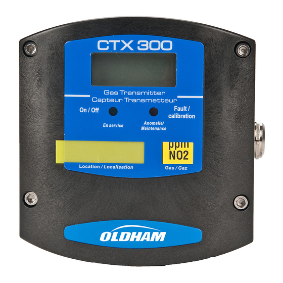
CTX 300 ANALOGIC GAS DETECTOR USER MANUAL CTX 300 overview CTX 300 Figure 27: with sensor pack and display – overview. NP300GB Revision O.0... - Page 35 CTX 300 ANALOGIC GAS DETECTOR USER MANUAL Figure 28: CTX 300 – overview. NP300GB Rev.O.0...
- Page 36 CTX 300 ANALOGIC GAS DETECTOR USER MANUAL Figure 29: CTX 300 semiconductor– overview. NP300GB Revision O.0...
- Page 37 CTX 300 ANALOGIC GAS DETECTOR USER MANUAL NP300GB Rev.O.0...
- Page 38 CTX 300 ANALOGIC GAS DETECTOR USER MANUAL NP300GB Revision O.0...
- Page 39 CTX 300 ANALOGIC GAS DETECTOR USER MANUAL NP300GB Rev.O.0...
- Page 40 No. 51 Jinzang Road, TX 77381, 62027 ARRAS Cedex, Shanghai Free Trade Zone, FRANCE CHINA Tel.: +1-713-559-9200 Tel.: +33 (0)3 21 60 80 80 Tel.: +86-134-8229-5057 www.teledynegasandflamedetection.com © 2021 TELEDYNE OLDHAM SIMTRONICS. All right reserved. NP300GB Revision O.0 / January 2021...
Need help?
Do you have a question about the CTX 300 and is the answer not in the manual?
Questions and answers