
Related Manuals for SharpEye 40

Summary of Contents for SharpEye 40
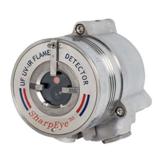
- Page 1 Model 40/40UFL Ultra Fast UV/IR Flame Detector User Guide www.acornfiresecurity.com...
- Page 2 www.acornfiresecurity.com www.acornfiresecurity.com...
- Page 3 Legal Notice The SPECTREX SharpEye Optical Flame Detector described in this document is the property of Rosemount. No part of the hardware, software or documentation may be reproduced, transmitted, transcribed, stored in a retrieval system or translated into any language or computer language, in any form or by any means, without prior written permission of Rosemount.
- Page 4 www.acornfiresecurity.com www.acornfiresecurity.com...
-
Page 5: Table Of Contents
www.acornfiresecurity.com Table of Contents Table of Contents .................... v List of Figures ....................ix List of Tables ....................x About this Guide ..................11 Release History ..................12 Glossary and Abbreviations ..............12 Notifications ..................14 Product Overview ..................15 Model and Types ................... - Page 6 Maintenance ..................50 5.1.1 General Procedures ................. 50 5.1.2 Periodic Procedures ................. 50 5.1.3 Keeping Maintenance Records ............51 Troubleshooting ..................51 Appendix A: Specifications ............... 53 Technical Specifications ................. 53 SharpEye™ Ultra Fast UV/IR Flame Detector User Guide www.acornfiresecurity.com...
- Page 7 www.acornfiresecurity.com Electrical Specifications ................53 A.2.1 Electrical Input Protection ..............54 Outputs ....................54 A.3.1 Electrical Interface ................54 A.3.2 Electrical Outputs ................55 A.3.3 Heated Optics ................. 56 Approvals..................... 57 A.4.1 Hazardous Area Approvals ............... 57 A.4.2 Functional Approvals ............... 57 Mechanical Specifications ...............
- Page 8 40/40UFL Flame Detector ..............79 E.1.1 Safety Relevant Parameters ............. 79 E.1.2 Guidelines for Configuring, Installing, Operating, and Service ....79 Appendix F: End of Line Resistor .............. 81 Technical Support ..................84 viii SharpEye™ Ultra Fast UV/IR Flame Detector User Guide www.acornfiresecurity.com...
-
Page 9: List Of Figures
Figure 4: Detector with Tilt Mount ............... 38 Figure 5: Tilt Mount Assembly ................39 Figure 6: Tilt Mount Assembly (dimensions in mm and inches) ........ 40 Figure 7: Detector with Cover Removed ............... 41 Figure 8: Wiring Terminals ................. 63 Figure 9: Typical Wiring for 4 Wire Controllers (Using Option 1 or 2 Wiring) ..... - Page 10 Table 10: Tools ....................35 Table 11: USA Version ..................39 Table 12: European Version ................39 Table 13: Model 40/40UFL Wiring Options ............42 Table 14: Functions ................... 45 Table 15: Default Function Values ............... 48 Table 16: Results of Successful Flame Simulator Test ..........49 Table 17: Troubleshooting Table .................
-
Page 11: About This Guide
About this Guide About this Guide This guide describes the SharpEye Model 40/40UFL Flame Detector and its features and provides instructions on how to install, operate, and maintain the detector. Note: This user guide should be read carefully by all individuals who have or will have responsibility for using, maintaining, or servicing the product. -
Page 12: Release History
Digital Signal Processing Electromagnetic Compatibility Electromagnetic Interference End of Line Field of View Highway Addressable Remote Transducer – HART communications protocol Immune at Any Distance International Electro-Technical Commission IECEx Explosion SharpEye™ Ultra Fast UV/IR Flame Detector User Guide www.acornfiresecurity.com... - Page 13 www.acornfiresecurity.com About this Guide Abbreviation/Term Meaning Internet Protocol Isopropyl Alcohol Infrared Refers to the 3 IR sensors in the VID Jet Fuel Light Emitting Diode Serial communications protocol using Master-Slave MODBUS messaging Not Applicable N.C. Normally Closed NFPA National Fire Protection Association N.O.
-
Page 14: Notifications
This indicates a situation that could result in minor injury and/or damage to the equipment. Note: This provides supplementary information, emphasizes a point or procedure, or gives a tip to facilitate operation. SharpEye™ Ultra Fast UV/IR Flame Detector User Guide www.acornfiresecurity.com... -
Page 15: Product Overview
Product Overview Product Overview Model 40/40UFL provides a combination of UV and IR sensors, where the IR sensor operates at a wavelength of 2.5–3.0µm. It can detect hydrocarbon-based fuel and gas fires, hydroxyl and hydrogen fires, as well as metal and inorganic fires with ultrafast ability to detect fire or an explosion in less than 20msec. -
Page 16: Model And Types
Required approval The configuration detail is included in the product part number on the product label and takes the form: 40/40UFL-XXXXX, where XXXXX defines the model according to the above requirements. To modify the default or pre-ordered configuration and perform maintenance tasks, please refer to the HART Protocol TM777030, the RS-485 Manual TM 777050 or TM777070. -
Page 17: Table 1: Wiring Options
Wiring option 1 is the default. The mA “Sink” output can be altered to “Source” type, with a link between terminals 1 and 8. No other wiring options can be changed onsite. Product number 40/40UFL-321SC has the following options: • Wiring Option: 3 (Power, Analog Output, RS-485, 0–20mA [Source] with the HART protocol, Fault Relay [N.O.], Alarm Relay [N.O., N.C.]) -
Page 18: Features And Benefits
2.3.1 Sensing Elements The IR sensor in Models 40/40UFL is sensitive to radiation over the range of 2.5– 3.0 microns where the H emission has a unique spectral peak that enables detection of hydrocarbon fires, gas fires, hydroxyl, and hydrogen fires, as well as metal and inorganic fires. -
Page 19: Detection Levels
2.3.3 Heated Optics The SharpEye 40/40 Flame Detector uses heated optics. The heater increases the temperature of the optical surface by 5–8°F / ~3–5°C above the ambient temperature to improve performance in ice, condensation, and snow conditions. -
Page 20: Rs-485 Modbus
Product Overview 2.3.5 RS-485 Modbus For more advanced communications, the 40/40UFL detector has an RS-485 Modbus-compatible output that provides data communication from a network (up to 247 detectors) to a host computer or universal controller for central monitoring. This feature allows for reduced installation costs, easy maintenance, and local or remote diagnostic tools. - Page 21 Ex db eb op is IIC T4 Gb Ex tb op is IIIC T106°C Db (–55°C ≤ Ta ≤ +85°C) The accessories, Tilt Mount P/N 40/40-001, Weather Cover P/N 777163 and P/N 777268, Duct Mount P/N 777670, and Air Shield P/N 777650 are included in the approval.
- Page 22 2.3.6.5 Inmetro (UL) The 40/40UFL Flame Detector is in compliance with the standards ABNT NBR IEC 60079-0, ABNT NBR IEC 60079-1, ABNT NBR IEC 60079-7, ABNT NBR IEC 60079-18, ABNT NBR IEC 60079-31, and INMETRO decree No. 179 as of May 18th, 2010.
-
Page 23: Performance Considerations
Product Overview 2.3.6.6 TR CU/EAC The 40/40UFL Flame Detector is in compliance with the standard TR CU 012/2011 per: 1 Ex db eb op is IIC T4 Gb X Ex tb op is IIIC T96°C Db X (–55°C ≤ Ta ≤ +75°C) 1 Ex db eb op is IIC T4 Gb X Ex tb op is IIIC T106°C Db X... -
Page 24: Table 2: Fuel Sensitivity Ranges
Polypropylene 43/13 Hydrogen 37/11 Methanol 26/8 Methane 26/8 Ethanol 95% 25/7.5 Ammonia 20/6 Paper 16/5 Silane 6/1.8 30”/0.75m high, 10”/0.25m width plume fire 20”/0.5m high, 8”/0.2m width plume fire SharpEye™ Ultra Fast UV/IR Flame Detector User Guide www.acornfiresecurity.com... -
Page 25: Cone Of Vision
Product Overview 2.4.2 Cone of Vision • Horizontal: 100° Figure 1: Horizontal Field of View • Vertical: +50° (down), –40° (up) Figure 2: Vertical Field of View TM40/40UFL Rev. (Al), February 2019 www.acornfiresecurity.com... -
Page 26: False Alarm Prevention
Mercury vapor lamp Grinding metal 3.3/1 Lit cigar Lit cigarette Match, wood, stick including flare up 3.3/1 Notes: IAD = Immune at Any Distance • All sources are chopped from 0–20Hz. • SharpEye™ Ultra Fast UV/IR Flame Detector User Guide www.acornfiresecurity.com... -
Page 27: Visual Indicators
Output Signals Outputs are available according to the default configuration or the wiring options selected for the 40/40UFL detector. Determine the outputs for your model according to Table 5. The detector incorporates several types of output suitable to different control systems: •... -
Page 28: Detector Status
A fault is detected when the power supply is too low or due to a software fault or electrical failure. The detector will NOT detect fire in this condition. In each state, the detector activates different outputs, as specified in Table 7. SharpEye™ Ultra Fast UV/IR Flame Detector User Guide www.acornfiresecurity.com... -
Page 29: Table 7: Output Signals Versus Detector State
www.acornfiresecurity.com Product Overview Table 7: Output Signals Versus Detector State Detector Alarm Auxiliary Fault State Indicator Mode Relay Relay Relay output Normal Green Warning 16mA Alarm Constant 20mA Latched Constant 20mA 20mA BIT Fault Yellow Warning at 16mA BIT Fault Alarm at Constant 20mA... -
Page 30: Auxiliary Relay As End-Of-Line
LED – Yellow flashes (4Hz) • Correcting the fault The fault indications remain until the detector’s power is removed. The fault indications return if the fault is still found when power is restored. SharpEye™ Ultra Fast UV/IR Flame Detector User Guide www.acornfiresecurity.com... -
Page 31: Built-In-Test (Bit)
www.acornfiresecurity.com Product Overview 2.5.3 Built-In-Test (BIT) The detector’s Built-In-Test (BIT) also checks the following: • Electronic circuitry • Sensors • Window cleanliness The detector can be set to perform the BIT automatically. 2.5.3.1 How the BIT Operates • The detector's status remains unchanged if the result of a BIT is the same as the current status (Normal or BIT Fault). -
Page 32: Table 9: Results Of An Unsuccessful Bit
Wiring options 3 and 5: changes to Closed • 0–20mA Wiring options 1, 2, and 3: BIT Fault (2mA) Output Power LED Yellow, Flashing, 4Hz BIT Procedure Performed every 1 minute SharpEye™ Ultra Fast UV/IR Flame Detector User Guide www.acornfiresecurity.com... -
Page 33: Installing The Detector
www.acornfiresecurity.com Product Overview Installing the Detector This chapter provides basic guidelines for installing the detector. It does not attempt to cover all of the standard practices and codes of installation. Rather, it emphasizes specific points of consideration and provides some general rules for qualified personnel. -
Page 34: Aiming The Detector
Model and Types on page 16. Required Tools The detector can be installed using general-purpose common tools and equipment. Table 10 lists the specific tools required to install the detector. SharpEye™ Ultra Fast UV/IR Flame Detector User Guide www.acornfiresecurity.com... -
Page 35: Certification Instructions
www.acornfiresecurity.com Product Overview Table 10: Tools Tool Function Comments Hex key ” Open and close detector cover (for Part of the kit wiring) Hex key ” Mount the detector on the tilt mount Part of the kit Flat screwdriver Connect ground terminal Standard tool Flat screwdriver Connect wires to the terminal blocks... -
Page 36: General Instructions
Follow this guideline for the cable installation: • All cables to the detector must be well shielded in order to comply with EMC requirement (see Electromagnetic Compatibility (EMC) on page 59). SharpEye™ Ultra Fast UV/IR Flame Detector User Guide www.acornfiresecurity.com... -
Page 37: Conduit Installation
www.acornfiresecurity.com Product Overview • Ground the detector to the nearest ground point (not more than 3m from the detector location). • Install the detector with the cable entries placed downwards. 3.6.1 Conduit Installation The conduit used for the cabling must comply with the following: •... -
Page 38: Installing The Tilt Mount
Product Overview Installing the Tilt Mount The tilt mount (P/N 40/40-001) enables the detector to be rotated up to 60º in all directions. Figure 4 shows the detector mounted on the tilt mount. Figure 4: Detector with Tilt Mount SharpEye™... -
Page 39: Tilt Mount Specifications
Product Overview 3.7.1 Tilt Mount Specifications Table 11: USA Version Item Type Location Tilt Mount 40/40-001 Screw ¼" 20 UNC x ¾" Detector – Holding plate Spring Washer No. ¼" Detector - Holding plate Table 12: European Version Item... -
Page 40: Figure 6: Tilt Mount Assembly (Dimensions In Mm And Inches)
The detector is now correctly located, aligned, and ready to be connected to the system. SharpEye™ Ultra Fast UV/IR Flame Detector User Guide www.acornfiresecurity.com... -
Page 41: Connecting The Detector
www.acornfiresecurity.com Product Overview Connecting the Detector This section describes how to connect the electric cabling to the detector (Figure To connect the detector to the electrical cables: Disconnect the power. Remove the back cover of the detector by removing 4 socket head-screws in the cover bolts. -
Page 42: Verifying The Detector Wiring
N.O. 0–20mA 0–20mA 0–20mA Auxiliary C Auxiliary C Out* RS-485+ RS-485+ RS-485+ RS-485+ RS-485+ RS-485- RS-485- RS-485- RS-485- RS-485- RS-485 RS-485 RS-485 RS-485 RS-485 GND Available with the HART protocol. SharpEye™ Ultra Fast UV/IR Flame Detector User Guide www.acornfiresecurity.com... -
Page 43: Configuring Your Detector
RS-485/USB converter, used with the SPECTREX host software, enables you to connect to any available PC or laptop to re-configure settings or perform diagnostics on all 40/40 series flame detectors. Refer to Manual TM777050 for programming instructions when using the USB RS-485 Harness Kit. -
Page 44: Alarm Delay
3.9.2 Address Setup The detector provides up to 247 addresses that can be changed with the RS-485 communication link or the HART protocol. SharpEye™ Ultra Fast UV/IR Flame Detector User Guide www.acornfiresecurity.com... -
Page 45: Function Setup
Yes: Auxiliary relay is used as End-of-Line. No: Auxiliary relay operates in accordance with Functions 2 and 5 (default). Only available in Models 40/40UFI-4XXXX and 5XXXX 3.9.4 Heated Optics The heated optics can be defined as one of the following modes: •... - Page 46 www.acornfiresecurity.com www.acornfiresecurity.com...
-
Page 47: Operating The Detector
www.acornfiresecurity.com Operating the Detector Operating the Detector This chapter describes how to power up and test the detector. It also includes some very important safety checks that you should complete before operating the detector. Powering Up This section describes how to turn on the detector. Follow these instructions carefully to obtain optimal performance from the detector over its life cycle: To power up the detector: Turn on the detector. -
Page 48: Default Functions Settings
In order to change the default function use: • USB RS-485 Harness Kit P/N 794079. Refer to Manual TM777050 for programming instructions when using the USB RS-485 Harness Kit. • HART protocol, refer to Manual TM777030 for instructions. SharpEye™ Ultra Fast UV/IR Flame Detector User Guide www.acornfiresecurity.com... -
Page 49: Testing Procedures
www.acornfiresecurity.com Operating the Detector Testing Procedures This section describes the proof testing procedure for proper operation of the detector. The detector can be tested with SPECTREX Flame Simulator FS-1200. The detector performs internal tests continuously and automatic BIT tests every 15 minutes. -
Page 50: Maintenance And Troubleshooting
Perform the power-up procedure every time power is restored to the system. Follow the instructions described in Powering Up on page 47. 5.1.2.2 Functional Test Procedure Perform a functional test of the detector as described in Internal Detector Tests on page 30. SharpEye™ Ultra Fast UV/IR Flame Detector User Guide www.acornfiresecurity.com... -
Page 51: Keeping Maintenance Records
www.acornfiresecurity.com Operating the Detector 5.1.3 Keeping Maintenance Records Maintenance operations performed on a detector should be recorded in a log book. The record should include the following: • Installation date • Contractor • Serial and tag number • Entries for every maintenance operation performed, including a description of the operation, date, and personnel ID If a unit is sent to SPECTREX or a distributor for service, a copy of the maintenance records should accompany it. - Page 52 www.acornfiresecurity.com www.acornfiresecurity.com...
-
Page 53: Appendix A: Specifications
Specifications Appendix A: Specifications Technical Specifications Spectral Response 40/40UFL UV:0.185–0.260µm IR:2.5–3.0µm Detection Range Fuel ft/m Fuel ft/m (at highest n-Heptane 66/20 Hydrogen 37/11 sensitivity setting Gasoline 66/20 Methane 26/8 for 1ft /0.1m Diesel Fuel 50/15 Methanol 26/8 fire) 50/15 Ethanol 95% 25/7.5... -
Page 54: Sharpeye™ Ultra Fast Uv/Ir Flame Detector User Guide
Option 1: Power, RS-485, Analog Output 0–20mA (Sink), Fault I Relay (N.C.), Alarm Relay, (N.O.) (see Figure 7). • Option 2: Power, RS-485, Analog Output 0–20mA (Source) and HART protocol, Fault Relay (N.O.), Alarm Relay, (N.O.), (N.C.). SharpEye™ Ultra Fast UV/IR Flame Detector User Guide www.acornfiresecurity.com... -
Page 55: Electrical Outputs
www.acornfiresecurity.com Specifications • Option 3: Power, RS-485, Analog Output 0–20mA (Source) and HART protocol, Fault Relay (N.O.), Alarm Relay (N.O., N.C.). • Option 4: Power, RS-485, Analog Output Fault Relay (N.C.), Auxiliary Relay (N.O.), Alarm Relay, (N.O.). • Option 5: Power, RS-485, Analog Output Fault Relay (N.O.), Auxiliary Relay (N.O.), Alarm Relay, (N.O.). -
Page 56: Heated Optics
Auto: Operated only when the change of temperature requires the heating (default) In Auto mode the start heating temperature can be defined between 32–86°F / 0–30°C. The detector stops heating the window when the temperature is 27°F/15°C above the start temperature. SharpEye™ Ultra Fast UV/IR Flame Detector User Guide www.acornfiresecurity.com... -
Page 57: Approvals
www.acornfiresecurity.com Specifications Approvals A.4.1 Hazardous Area Approvals • Class I Div. 1 Groups B, C, and D; Class II/III Div. 1 Groups E, F, and G • ATEX, IECEx Ex II 2G D Ex db eb op is IIC T4 Gb Ex tb op is IIIC T96°C Db (–55°C ≤... -
Page 58: Enclosure
4” x 4.6” x 6.18” / 101.6 x 117 x 157 mm A.5.6 Weight • Stainless Steel: 6.1lb/2.8kg • Aluminum: 2.8lb/1.3kg Environmental Specifications The SharpEye 40/40UFL is designed to withstand harsh environmental conditions. A.6.1 High Temperature • Designed to meet MIL-STD-810C, Method 501.1 Procedure II • Operating temperature: +167°F/+75 °C •... -
Page 59: Salt Fog
www.acornfiresecurity.com Specifications • Relative humidity of up to 95% for the operational temperature range A.6.4 Salt Fog • Designed to meet MIL-STD-810C, Method 509.1, Procedure I • Exposure to a 5% salt solution fog for 48 hours A.6.5 Dust • Designed to meet MIL-STD-810C, Method 510.1, Procedure I •... - Page 60 Specifications shielded and the detector must be grounded. The shield should be grounded at the detector end. SharpEye™ Ultra Fast UV/IR Flame Detector User Guide www.acornfiresecurity.com...
-
Page 61: Appendix B: Wiring Instructions
1.07 3.50 0.81–0.96 0.67 2.20 1.22–1.43 0.43 1.40 1.94–2.28 0.27 0.88 Use Table 23 to select wire gauge for power supply wires. DO NOT connect any circuit or load to detectors’ supply inputs. • Select number of detectors connected in 1 circuit. -
Page 62: Calculation Formula
Calculate the voltage drop in the wire as follows: 2 x 1000 x 1.4Ω x 1 x 0.2A = 5.6V The minimum voltage of the power supply should be 20V + 5.6V = 25.6V SharpEye™ Ultra Fast UV/IR Flame Detector User Guide www.acornfiresecurity.com... -
Page 63: Typical Wiring Configurations
www.acornfiresecurity.com Wiring Instructions Typical Wiring Configurations This section describes examples of typical wiring configurations. Figure 8: Wiring Terminals TM40/40UFL Rev. (Al), February 2019 www.acornfiresecurity.com... -
Page 64: Figure 9: Typical Wiring For 4 Wire Controllers (Using Option 1 Or 2 Wiring)
(N.O.) Output (N.O.) 40/40UFL - Analog Fault Relay Auxiliary Auxiliary Relay 5XXXX (N.O.) Relay (N.O.) Output (N.O.) Figure 9: Typical Wiring for 4 Wire Controllers (Using Option 1 or 2 Wiring) SharpEye™ Ultra Fast UV/IR Flame Detector User Guide www.acornfiresecurity.com... -
Page 65: Figure 10: 0-20Ma Wiring Option 1 (Sink 4-Wire) - Default
www.acornfiresecurity.com Wiring Instructions Figure 10: 0–20mA Wiring Option 1 (Sink 4-Wire) – Default Figure 11: 0–20mA Wiring Option 1 (Converted to Source 3-Wire) TM40/40UFL Rev. (Al), February 2019 www.acornfiresecurity.com... -
Page 66: Figure 12: 0-20Ma Wiring Option 1 (Non-Isolated Sink 3-Wire)
Figure 12: 0–20mA Wiring Option 1 (Non-isolated Sink 3-Wire) Figure 13: 0–20mA Wiring Option 2 and 3 Notes: There are no 0–20mA outputs in wiring options 4 and 5. • Source 3-wire available with the HART Protocol. • SharpEye™ Ultra Fast UV/IR Flame Detector User Guide www.acornfiresecurity.com... -
Page 67: Appendix C: Rs-485 Communication Network
www.acornfiresecurity.com RS-485 Communication Network Appendix C: RS-485 Communication Network RS-485 Overview By using the RS-485 network capability of the UV/IR detector and additional software, it is possible to connect up to 32 detectors in an addressable system with 4 wires only (2 for power and 2 for communication). Using repeaters, the number of detectors can be much larger (32 detectors for each repeater) up to 247 on the same 4 wires. - Page 68 www.acornfiresecurity.com www.acornfiresecurity.com...
-
Page 69: Appendix D: Accessories
This appendix describes the accessories that can help you maximize fire detection with the SharpEye UV/IR flame detector: Flame Simulator FS-1200 The Flame Simulator FS-1200 is designed specifically for use with SharpEye Flame Detectors. The FS-1200 includes a halogen lamp that emits UV and IR energy. This energy is accumulated by a reflector directed towards the detector. -
Page 70: Unpacking
Push the activate button, and then use the laser spot for fine adjustment towards the center of the detector. Keep the simulator aimed at the detector for up to 50 seconds until you trigger an alarm. Wait 20 seconds before repeating the test. SharpEye™ Ultra Fast UV/IR Flame Detector User Guide www.acornfiresecurity.com... -
Page 71: Range
D.1.4 Range Table 25: Sensitivity Ranges Detector Type Detector Sensitivity Setting Maximum Testing (ft/m) Distance (ft/m) 40/40UFL 60/20 23/7 Notes: The minimum distance from the detector is 20”/50cm. • The optional beam collimator is fitted for extended range. • At extreme temperatures, there is a 15% maximum reduction in •... -
Page 72: Battery Replacement
SPECTREX battery pack, P/N 380004. Screw on the locking disc (Item 3). Screw on the back cover (Item 4). Lock the back cover with the locking screw. Note: For more information refer to TM380002. SharpEye™ Ultra Fast UV/IR Flame Detector User Guide www.acornfiresecurity.com... -
Page 73: Technical Specifications
www.acornfiresecurity.com Accessories Technical Specifications D.2.1 General • Temperature Range: –4°F to +122ºF / –20ºC to +50ºC • Vibration Protection: 1g (10–50Hz) D.2.2 Electrical • Power: 14.8V (4 X 3.7V rechargeable lithium-ion battery) • Max. Current: 4A • Battery Capacity: 2.2AH •... -
Page 74: Tilt Mount
IEC 61000-6-3 40dbuv/m (30–230MHz), Like Class B Emission 47dbuv/m (230MHz–1GHz) of EN 55022 Tilt Mount The tilt mount (P/N 40/40-001) provides accurate directional selection for optimum area coverage. Figure 17: Tilt Mount SharpEye™ Ultra Fast UV/IR Flame Detector User Guide www.acornfiresecurity.com... -
Page 75: Duct Mount
Accessories Duct Mount The duct mount (P/N 777670) is suitable for use with the SharpEye 40/40 Series Optical Flame Detector 40/40UFL, for both the aluminum and st.st. enclosure. The duct mount allows flame detection in areas where high temperatures exist or where the detector cannot be installed inside the area. -
Page 76: Weather Cover
Accessories Weather Cover The weather cover (P/N 777163) protects the detector from different weather conditions, such as snow and rain. Figure 19: Weather Cover SharpEye™ Ultra Fast UV/IR Flame Detector User Guide www.acornfiresecurity.com... -
Page 77: Air Shield
Accessories Air Shield The air shield (P/N 777650) is suitable for use with the SharpEye 40/40 Series Optical Flame Detector 40/40UFL, for both the aluminum and st.st. enclosures. Optical flame detectors are often used in highly polluted or dirty areas that force maintenance personnel to access the detector frequently in order to clean its optical window. - Page 78 www.acornfiresecurity.com www.acornfiresecurity.com...
-
Page 79: Appendix E: Sil-2 Features
The setup parameters must be verified (as described in Using the 0–20mA Interface for Alerting on page 79; and in Using the Alarm Relay Contact for Alerting on page 80). The function of the 40/40 Flame Detector (flame detection, function of the 0–20mA interface, and relay functions) must be checked completely. - Page 80 The window of the sensor must be examined at appropriate time intervals for partial contamination. • The HART and the RS-485 interfaces must not be used for the transmission of safety-related data. SharpEye™ Ultra Fast UV/IR Flame Detector User Guide www.acornfiresecurity.com...
-
Page 81: Appendix F: End Of Line Resistor
End of Line Resistor Appendix F: End of Line Resistor The 40/40 series can be equipped with an EOL resistor inside the flameproof 'd' terminal compartment. The EOL resistor can be situated in the rear part which is Ex e or Ex d , depending on the application. - Page 82 www.acornfiresecurity.com www.acornfiresecurity.com...
- Page 83 www.acornfiresecurity.com www.acornfiresecurity.com...
-
Page 84: Technical Support
www.acornfiresecurity.com www.acornfiresecurity.com...
Need help?
Do you have a question about the 40 and is the answer not in the manual?
Questions and answers