Advertisement

This manual should be considered a permanent part of the vehicle
and should remain with the vehicle when it is resold.
This publication includes the latest production information available
before printing. Honda Motor Co., Ltd. reserves the right to make
changes at any time without notice and without incurring any
obligation.
No part of this publication may be reproduced without written
permission.
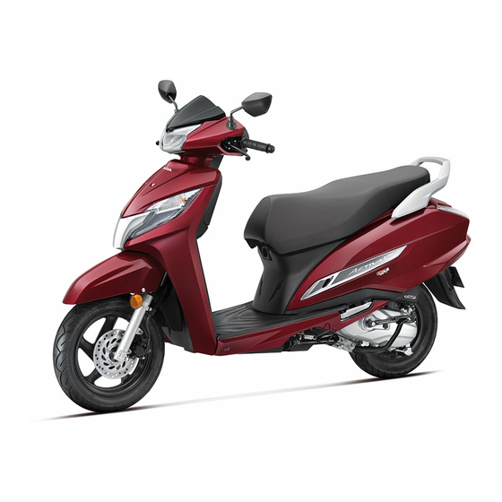
The vehicle pictured in this owner's manual may not match your
actual vehicle.
For any query or assistance, please call Customer care number:
1800 103 3434 (Toll free)
© 2019 Honda Motor Co., Ltd.

Advertisement

Table of Contents
loading

Summary of Contents for Honda ACTIVA 125 2019

  • Page 1 This publication includes the latest production information available before printing. Honda Motor Co., Ltd. reserves the right to make changes at any time without notice and without incurring any obligation.
  • Page 2 Welcome Congratulations on your purchase of a new The following codes in this manual indicate Honda vehicle. Your selection of a Honda the country. makes you part of a worldwide family of The illustrations here in are based on the satisfied customers who appreciate Honda’s...
  • Page 3 A Few Words About Safety DANGER Your safety, and the safety of others, is very important. Operating this vehicle safely is an You WILL be KILLED or SERIOUSLY important responsibility. HURT if you don’t follow instructions. To help you make informed decisions about safety, we have provided operating WARNING procedures and other information on safety...
  • Page 4: Table Of Contents

    Contents Vehicle Safety P. 2 Operation Guide P. 14 Maintenance P. 50 Troubleshooting P. 95 Information P. 109 Specifications P. 120 Warranty Policy P. 123 Index P. 131...
  • Page 5: Vehicle Safety

    Vehicle Safety This section contains important information for safe riding of your vehicle. Please read this section carefully. Safety Guidelines P. 3 ............Image Labels P. 6 ............... Safety Precautions P. 8 ............Riding Precautions P. 9 ............Accessories & Modifications P.
  • Page 6: Safety Guidelines

    Safety Guidelines Safety Guidelines that you and your passenger are both wearing an approved helmet and protective apparel. Follow these guidelines to enhance your safety: Instruct your passenger on holding onto the Perform all routine and regular inspections grab rail or your waist, leaning with you in turns, specified in this manual.
  • Page 7 Safety Guidelines Make Yourself Easy to See Keep Your Honda in Safe Condition Make yourself more visible, especially at night, It’s important to keep your vehicle properly by wearing bright reflective clothing, maintained and in safe riding condition. positioning yourself so other drivers can see...
  • Page 8 Safety Guidelines leaks, check the tightness of critical nuts and WARNING bolts, and check the handlebar, control levers, brakes, and wheels. Ride slowly and cautiously. Running the engine of your vehicle Your vehicle may have suffered damage that is while in an enclosed or even partially not immediately apparent.
  • Page 9: Image Labels

    Image Labels Image Labels Read instructions contained in Owner’s Manual carefully. The following pages describe the label meanings. Some labels warn you of potential Read instructions contained in Shop hazards that could cause serious injury. Others Manual carefully. In the interest of provide important safety information.
  • Page 10 Image Labels BATTERY LABEL DANGER • Keep flame and spark away from the battery. Battery produce explosive gas that can cause explosion. • Wear the eye protection and rubber gloves when handling the battery, or you can get burned or lose your eyesight by the battery electrolyte.
  • Page 11: Safety Precautions

    Safety Precautions Safety Precautions Face shield with unobstructed field of vision or other approved eye protection Ride cautiously and keep your hands on the WARNING handlebar and feet on the floor. Keep passenger’s hands onto the grab rail or Not wearing a helmet increases the your waist, passenger’s feet on the footpegs chance of serious injury or death in a while riding.
  • Page 12: Riding Precautions

    Riding Precautions Riding Precautions ► Repeated braking, such as when descending long, steep slopes can Running-in Period seriously overheat the brakes, reducing their effectiveness. During the first 500 km (300 miles) of running, For full braking effectiveness, operate both follow these guidelines to ensure your vehicle’s the front and rear brakes together.
  • Page 13 Riding Precautions If the brakes get wet, apply the brakes while SCV125 II ID, III ID riding at low speed to help them dry. Parking with the Side Stand or Centre ▌ Stand Parking 1. Stop the engine. Park on a firm, level surface. 2.
  • Page 14 Riding Precautions SCV125 ID 3. Turn the handlebar fully to the left. 4. Turn the ignition switch to the LOCK position Parking with the Centre Stand ▌ P. 31 , remove the key and close the shutter 1. Stop the engine. P.
  • Page 15: Accessories & Modifications

    We strongly advise that you do not add any seriously hurt or killed. accessories that were not specifically designed for your vehicle by Honda or make Follow all instructions in this owner’s modifications to your vehicle from its original manual regarding accessories and design.
  • Page 16: Loading

    Loading Loading WARNING Carrying extra weight affects your vehicle’s Overloading or improper loading can handling, braking and stability. cause a crash and you can be seriously Always ride at a safe speed for the load you hurt or killed. are carrying. Avoid carrying an excessive load and keep Follow all load limits and other loading within specified load limits.
  • Page 17: Operation Guide

    Basic Operation Flow Pre-ride Inspection P. 55 Acceleration P. 41 Carefully inspect your vehicle to make sure that it is safe to ride. Apply throttle gradually. Obey the speed limit. Starting the Engine P. 37 Start and warm the engine. Avoid revving the engine.
  • Page 18 Braking Parking P. 42 P. 10 Park on a firm level surface. Use Close the throttle and apply the the stand, Set the parking brake, front and rear brakes together. lock the steering and close the f The brakelight will indicate that shutter.
  • Page 19 Parts Location Tool kit / Document bag / First aid kit P. 48 Helmet holder Spark plug P. 46 P. 72 Throttle grip P. 91 SCV125 II ID Front brake fluid reservoir P. 78 Front brake lever Ignition Switch P. 30 Luggage hook P.
  • Page 20 Headlight P. 104 Rear brake lock lever Rear brake lever Seat P. 45 Center compartment P. 47 Grab rail Fuel fill cap P. 43 Rear suspension spring preload adjuster P. 94 Air cleaner P. 63 Crankcase breather P. 92 Kickstarter Centre stand Engine oil drain bolt P.
  • Page 21 Instruments SCV125 ID Odometer Total distance ridden Fuel gauge Needle in the red mark, remaining fuel approximately: 1.0 L (0.26 US gal, 0.22 Imp gal) Speedometer This shows riding speed in kilometer per hour (km/h)
  • Page 22 SCV125 II ID, III ID SERVICE DUE indicator P. 24 SEL button Clock (12-hour display) To set the clock P. 23 Speedometer This shows riding speed in kilometer per hour (km/h) Display Check When the ignition switch is turned ON, all the modes and digital segments will show. If any part of these displays do not come on when it should, have your dealer check for problems.
  • Page 23 Instruments (Continued) Fuel gauge Remaining fuel when only 1st (E) segment starts flashing approximately: 1.0 L (0.26 US gal, 0.22 Imp gal) If the fuel gauge indicator flashes in a repeat pattern or turns off: P. 98...
  • Page 24 Odometer [TOTAL] / Tripmeter [TRIP] / Current fuel mileage / Average fuel mileage [AVG] / Available driving distance [RANGE] SEL button selects the odometer, tripmeter, current fuel mileage, average fuel mileage and available driving distance. Current fuel Odometer Tripmeter mileage P.
  • Page 25 Instruments (Continued) • Current fuel mileage: Displays instant fuel mileage. If your speed is less than 5±2 km/h or immediately after ignition switch is turned to ON, “--.-” is displayed. When “--.-” is displayed on other cases, go to your dealer for service. •...
  • Page 26 Clock Setting: Press SEL button until the desired minute is displayed. Turn the ignition switch to the ON position. Minute will advance by one minute, With odometer (TOTAL) displayed, press each time SEL button is pressed. and hold the SEL button until ECO indicator starts flashing.
  • Page 27 First blinking of service due indicator will whenever your vehicle reach specified kilometer. start 250 km before first service (as per Kindly visit your Honda dealer for service due specified distance) of the vehicle. indicator resetting.
  • Page 28 Indicators SCV125 ID If one of these indicators does not come on when it should, have your dealer check for problems. Left turn signal indicator Right turn signal indicator PGM-FI (Programmed Fuel Injection) malfunction indicator lamp (MIL) Comes on briefly when the ignition switch is turned to the ON position.
  • Page 29 Indicators (Continued) SCV125 II ID, III ID Left turn signal indicator ECO indicator P.28 Right turn signal indicator Side stand indicator Comes on when the side stand is lowered. High beam indicator...
  • Page 30 PGM-FI (Programmed Fuel Injection) malfunction indicator lamp (MIL) Comes on briefly when the ignition switch is turned to the ON position. If it comes on while engine is running: P. 97 Idling Stop indicator SCV125 II ID Comes on briefly when the Idling Stop switch is in the IDLING STOP position with the ignition switch turned on.
  • Page 31 Indicators (Continued) ECO indicator To set the desired option, press and hold SEL button until the hour digits start When fuel consumption improves the ECO flashing. indicator will come on. Press and hold SEL button until minute When the scooter comes to a stop, the ECO digits start flashing.
  • Page 32 Switches Fuel lid / seat opener switch Pressing the switch opens the fuel lid and seat. To open the seat: P. 45 To open the fuel lid: P. 43 Engine stop switch / Start button SCV125 ID, III ID Should normally remain in the (Run) Horn button position.
  • Page 33 Switches (Continued) Ignition switch Switches the electrical system on/off, locks the steering, and operates the fuel lid and seat opener switch. Key can be removed when in the OFF or LOCK position. Start button Turns electrical system SCV125 II ID on for starting/riding.
  • Page 34 Steering Lock Locking Turn the handlebar all the way to the left. Lock the steering when parking to help Push the key down, and turn the ignition prevent theft. switch to the LOCK position. A U-shaped wheel lock or similar device is Jiggle the handlebar if the lock is also recommended.
  • Page 35 Switches (Continued) Shutter Close The ignition switch for this vehicle is Remove the ignition key from the ignition equipped with a shutter. After parking the switch. vehicle, close the shutter for theft Align the projection of the shutter key with prevention.
  • Page 36 Rear Brake Lock Unlocking Be sure the rear brake lock is applied while Squeeze the rear brake lever. starting and warming up the engine. u Before riding, make sure that the rear brake lock is fully released so there is no drag on Locking the rear wheel.
  • Page 37 Idling Stop System SCV125 II ID Activation of the Idling Stop System The Idling Stop system becomes ready to Idling Stop system is designed to help stop the engine and Idling Stop indicator reduce the fuel consumption and noise, by comes on when the following requirements idling stop while making a stop such as are satisfied with the Idling Stop switch in...
  • Page 38 Stopping the engine by the Idling Stop System Safety Precaution for the Idling Stop System The engine stops and Idling Stop indicator Do not go away from the vehicle while the changes to flash after you close the throttle Idling Stop indicator is flashing. When you completely and stop the vehicle while the go away from the vehicle, always turn the Idling Stop indicator is on.
  • Page 39 Idling Stop System (Continued) Restarting the Engine Engine Does Not Start Even If the Check that the Idling Stop indicator is Throttle is Opened: P. 101 flashing, and then open the throttle. NOTICE If it is not flashing, you can’t restart the Headlight stays on after the engine is stopped by the engine with the Idling Stop system, even if Idling Stop system.
  • Page 40 Starting the Engine Start your engine using the following NOTICE procedure, regardless of whether the engine • If the engine does not start within 5 seconds, turn the is cold or warm. ignition switch to the OFF position and wait 10 seconds before trying to start the engine again to recover SCV125 II ID, III ID battery voltage.
  • Page 41 Starting the Engine (Continued) Place the vehicle on its centre stand. Turn the ignition switch to the ON position. To Start the Engine with Electric Starter With the throttle closed, press the start button. Squeeze the rear brake lever. Release the start button as soon as the engine starts SCV125 ID The starter motor will only work when...
  • Page 42 If you cannot start the engine: To Start the Engine with Kickstarter Open the throttle slightly (about 3 mm, With the throttle completely closed, without freeplay) while starting the engine. operate the kickstarter starting from the top of the stroke, kick through to the About 3 mm, without freeplay bottom with a rapid, continuous motion.
  • Page 43 Starting the Engine (Continued) If the engine does not start: Using the kickstarter Using the start button Turn off the ignition switch. Open the throttle fully and press the start Open the throttle fully. button for 5 seconds. Crank the engine several times with the Repeat the normal starting procedure.
  • Page 44 Riding Starting the vehicle Acceleration and deceleration. To accelerate: Open the throttle slowly. Push the vehicle forward off the centre To decelerate: Close the throttle. stand. Lock the rear brake lock. Keep throttle closed. Open Close (Accelerate) SCV125 II ID, III ID (Decelerate) Make sure the side stand and centre stand are up.
  • Page 45 Riding (Continued) Braking Close the throttle and apply the front and rear brake levers together. Do not apply the brake lock while riding. It may cause the wheel to lock, reducing control of the vehicle. Rear brake lever Front brake lever...
  • Page 46 Refuelling Do not fill with fuel above the lower edge of FUEL SEAT FUEL the filler neck. Fuel type: Unleaded petrol only Fuel octane number: Your vehicle is designed to use Research Octane Number Ignition key (RON) 90 or higher. Tank capacity: 5.3 litres (1.40 US gal, 1.17 Fuel lid / seat Imp gal)
  • Page 47 Refuelling (Continued) Closing the Fuel Fill Cap Turn the fuel fill cap counterclockwise until it stops and remove the cap. Install and tighten the fuel fill cap firmly by turning it clockwise. Fuel fill cap 5 marks Make sure that the 5 marks on the fuel fill cap and fuel tank are aligned.
  • Page 48 Storage Equipment Seat Open Insert the ignition key and turn it to the Seat FUEL SEAT position. To unlock the shutter and steering lock P. 32 P. 31 Turn the handlebar pointed straight ahead. Press the SEAT side of the fuel lid / seat opener switch.
  • Page 49 Storage Equipment (Continued) Helmet Holders WARNING The helmet holders are located under the Riding with a helmet attached to the seat. holder can interfere with your ability u Use the helmet holder only when parked. to safely operate the vehicle and could lead to a crash in which you can be seriously hurt or killed.
  • Page 50 Front inner box Center compartment Never exceed the maximum weight limit. Never exceed the maximum weight limit. Maximum Weight: 0.5 kg (1 lb) Maximum Weight: 10 kg (22 lb) u Do not store any items that are flammable To open or susceptible to heat damage.
  • Page 51 Storage Equipment (Continued) Tool Kit/ Document Bag/ First Aid Kit Tool kit, document bag and first aid kit is located in the center compartment. Tool kit Document bag First aid kit...
  • Page 52 Luggage Hook Luggage hook The luggage hooks are provided below the handlebar and the seat. u Do not attach large luggage to the hook that would hang out from the vehicle and/ or interfere with the movement of your feet and handle operation.
  • Page 53: Maintenance

    Maintenance Please read “Importance of Maintenance” and “Maintenance Fundamentals” carefully before attempting any maintenance. Refer to “Specifications” for service data. Importance of Maintenance P. 51 Engine Oil P. 74 ......................Maintenance Schedule P. 52 Brakes P. 78 ..........................Maintenance Fundamentals P.
  • Page 54: Importance Of Maintenance

    Importance of Maintenance Importance of Maintenance Maintenance Safety Keeping your vehicle well-maintained is Always read the maintenance instructions before you begin each task, and make sure that absolutely essential to your safety and to protect you have the tools, parts, and skills required. your investment, obtain maximum performance, We cannot warn you of every conceivable avoid breakdowns, and reduce air pollution.
  • Page 55: Maintenance Schedule

    Maintenance work should be performed in new owner. accordance with Honda’s standards and specifications by properly trained and Honda recommends that your dealer should equipped technicians. Your dealer meets all road test your vehicle after each periodic of these requirements. Keep an accurate maintenance is carried out.
  • Page 56 : Intermediate. We recommend service by your dealer, unless you have the necessary tools and are mechanically skilled. : Replace Procedures are provided in an official Honda Shop Manual. : Clean : Technical. In the interest of safety, have your vehicle serviced by your dealer.
  • Page 57 Maintenance Schedule Frequency Pre-ride Annual Regular Refer to × 1,000 km Items Check Check Replace page × 1,000 mile 0.6 P. 55 Months Brake Shoes Wear (ID, III ID) Brake Shoes / Pads Wear (II ID) 79, 83 Brake System Brake Lock Operation –...
  • Page 58: Maintenance Fundamentals

    Maintenance Fundamentals Pre-ride Inspection SCV125 ID, III ID Front and Rear: check shoes wear and To ensure safety, it is your responsibility to freeplay, adjust if necessary. P. 89, 84 perform a pre-ride inspection and make sure Lights and horn - Check that lights, that any problem you find is corrected.
  • Page 59 Maintenance Fundamentals Replacing Parts Battery Always use Honda Genuine Parts or their Your vehicle has a maintenance-free type equivalents to ensure reliability and safety. battery. You do not have to check the battery electrolyte level or add distilled water. Clean the...
  • Page 60 Maintenance Fundamentals What to do in an emergency WARNING If any of the following occur, immediately see your doctor. The battery gives off explosive hydrogen Electrolyte splashes into your eyes: gas during normal operation. ►Wash your eyes repeatedly with cool water for at least 15 minutes.
  • Page 61 3. If the terminals are heavily corroded, clean maintenance-free battery of the same type. and polish the terminals with a wire brush or sandpaper. Wear safety glasses. NOTICE Installing non-Honda electrical accessories can overload the electrical system, discharging the battery and possibly damaging the system.
  • Page 62 Selecting the Engine Oil Blown fuse For recommended engine oil, see “Specifications.” P. 121 If you use non-Honda engine oil, check the label to make sure that the oil satisfies all of the following standards: NOTICE JASO T 903 standard...
  • Page 63 . The API classification specifies the quality and Recommended brake fluid: performance rating of engine oils. Use SJ or Honda DOT 3 or DOT 4 Brake Fluid or higher oils, excluding oils marked as “Energy Conserving” or “Resource Conserving” on the equivalent circular API service symbol.
  • Page 64 Maintenance Fundamentals Crankcase Breather Tyres (Inspecting/Replacing) Checking the Air Pressure Service more frequently when riding in rain, at full throttle, or after the vehicle is washed or Visually inspect your tyres and use an air overturned. Service if the deposit level can be pressure gauge to measure the air pressure at seen in the transparent section of the drain least once a month or any time you think the...
  • Page 65 Maintenance Fundamentals Inspecting for Abnormal Wear WARNING Inspect the tyres for signs of abnormal Riding on tyres that are excessively wear on the contact worn or improperly inflated can cause surface. a crash in which you can be seriously hurt or killed. Follow all instructions in this owner’s Inspecting Tread Depth manual regarding tyre inflation and...
  • Page 66 Maintenance Fundamentals Air Cleaner Do not install a tube inside a tubeless tyre on this vehicle. Excessive heat build-up can This vehicle is equipped with a viscous type air cause the tube to burst. cleaner element. Use only tubeless tyres on this vehicle. Air blow cleaning or any other cleaning can The rims are designed for tubeless tyres, and degrade the viscous element performance and...
  • Page 67: Tool

    Tool The tool kit is stored in the center compartment. P. 48 You can perform some roadside repairs, minor adjustments and parts replacement with the provided tools. Spark plug wrench 12 x 14 mm Open end wrench Standard / Philips Screwdriver...
  • Page 68: Removing & Installing Body Components

    Removing & Installing Body Components Battery 3. Disconnect the negative terminal from the battery. 4. Disconnect the positive terminal from Removal the battery. Make sure the ignition switch is in the OFF 5. Remove the battery taking care not to position.
  • Page 69: Battery Lid

    Removing & Installing Body Components Battery Lid Battery Lid 2. Remove the screws and battery lid. Screw Removal 1. Remove the floor mat. Battery lid Floor mat Installation Install the parts in the reverse order of removal.
  • Page 70: Body Cover

    Removing & Installing Body Components Body Cover Body Cover Bolts Clip Lift-up 1. Open the seat. P. 45 2. Remove the bolts. 3. Remove the clips. P. 68 4. Lift-up the body cover and set the maintenance rod. Installation Clip Install the parts in the reverse order of removal.
  • Page 71: Clip

    Removing & Installing Body Components Clip Clip Removal : 1. Press down on the centre pin to release the lock. 2. Pull the clip out of the hole. Centre Installation : 1. Push the bottom of the centre pin. 2. Insert the clip into the hole. 3.
  • Page 72: Front Centre Cover

    Removing & Installing Body Components Front Centre Cover Removal Front Centre Cover 1. Remove the screws. 2. Remove the front centre cover by Screws releasing the snap fit clips. Front centre cover Installation Install the parts in the reverse order of removal.
  • Page 73: Headlight Case

    Removing & Installing Body Components Headlight Case Removal Headlight Case 1. Pull up the rubber dust covers. 2. Loosen the lock nuts by turning clockwise. Rearview mirrors 3. Loosen the rearview mirrors and remove them by turning them clockwise until they Rubber dust covers will no longer turn.
  • Page 74 Removing & Installing Body Components Headlight Case Installation Headlight case Screw B Install the parts in the reverse order of Rear handle cover removal. To install the rearview mirrors. 1. Install the mirror adapters. 2. Install the rearview mirrors by turning counterclockwise until they will no longer turn.
  • Page 75: Spark Plug

    Spark Plug Checking Spark Plug Spark plug wrench Spark plug cap For the recommended spark plug, see “Specifications.” P. 121 Use only the recommended type of spark plug in the recommended heat range. NOTICE Using a spark plug with an improper heat range can cause engine damage.
  • Page 76 Spark Plug Checking Spark Plug 6. Check the spark plug gap using a wire 9. Tighten the spark plug: type feeler gauge. If the old plug is good: If adjustment is necessary, bend the 1/12 turn after it seats. side electrode carefully. If installing a new plug, tighten it twice to prevent loosening: The gap should be:...
  • Page 77: Engine Oil

    Engine Oil Checking the Engine Oil Oil fill cap/dipstick SCV125 II ID Upper Level Check the engine oil with the Idling Stop switch at IDLING. SCV125 ID, II ID, III ID 1. If the engine is cold, idle the engine for 3 to 5 minutes.
  • Page 78 Engine Oil Adding Engine Oil Adding Engine Oil NOTICE Overfilling with oil or operating with insufficient oil can If the engine oil is below or near the lower cause damage to your engine. Do not mix different level mark, add the recommended engine brands and grades of oil.
  • Page 79 Engine Oil Changing Engine Oil, Cleaning Strainer Screen 2. Turn the ignition switch to the OFF position Sealing washer and wait for 2 to 3 minutes. 3. Place your vehicle on its centre stand on a firm, level surface. 4. Place a drain pan under the drain bolt and oil plug.
  • Page 80 Engine Oil Changing Engine Oil, Cleaning Strainer Screen 11. Install a new sealing washer onto the drain bolt. Tighten the drain bolt. Torque: 24 N·m (2.4 kgf·m, 18 lbf·ft). 12. Fill the crankcase with the recommended oil ( P. 59, 121) and install the oil fill cap/ dipstick.
  • Page 81: Brakes

    Brakes SCV125 II ID Front brake fluid reservoir Checking the Front Brake Fluid 1. Place your vehicle in an upright position on a firm, level surface. 2. Check that the brake fluid reservoir is horizontal and that the fluid level is above the LWR level mark.
  • Page 82 Brakes Inspecting the Front Brake Pads SCV125 II ID Brake pads Inspecting the Front Brake Pads Wear Wear Check the condition of the brake pad wear indicators indicators indicators. The pads need to be replaced if a brake pad is worn to the bottom of the indicator. 1.
  • Page 83 Brakes Inspecting the Rear Brake Lever Freeplay SCV125 II ID Check the brake cable for kinks or signs of wear. If necessary have it replaced by your Inspecting the Rear Brake dealer. Lever Freeplay Lubricate the brake cable with a commercially available cable lubricant to prevent 1.
  • Page 84 Brakes Adjusting the Rear Brake Lever Freeplay 1. Adjust by turning the rear brake adjusting SCV125 II ID nut a half-turn at a time. Adjusting the Rear Brake Lever Freeplay Adjust the freeplay of the brake lever with the front wheel pointed straight ahead. Make sure the cut-out on the adjusting nut is Brake seated on the brake arm pin when adjusting...
  • Page 85 Brakes Adjusting the Rear Brake Lever Freeplay 3. Push the brake arm to confirm that there is After adjustment, confirm the freeplay of the a gap between the rear brake adjusting nut brake lever. and rear brake arm pin. Make sure the brake arm, spring and fastener are in good condition.
  • Page 86 The rear brake is equipped with a brake wear See your dealer for this service. indicator. When the brake service is necessary, see Brake panel your dealer. Use only Honda Genuine Parts Arrow or its equivalent. Reference mark Brake arm...
  • Page 87 Brakes Inspecting the Brake Lever Freeplay SCV125 ID, III ID SCV125 ID, III ID Inspecting the Brake Lever Adjusting the Brake Lever Freeplay Freeplay 1. Place your vehicle on its centre stand on a Adjust the freeplay of the brake levers with firm, level surface.
  • Page 88 Brakes Adjusting the Brake Lever Freeplay 1. Turn No.1 adjusting nut a half-turn at a 2. Without pushing the brake arm, adjust time while firmly pushing the brake arm. No.2 adjusting nut so that the gaps Check the freeplay of the front brake lever between the brake arm and brake arm pin after turning the adjusting nut clockwise for No.1 and No.2 are as follows.
  • Page 89 Brakes Adjusting the Brake Lever Freeplay 3. While pushing the front brake arm, To adjust No.2 adjusting nut, turn the No.2 adjusting nut a half-turn at a time confirm there is a gap between the brake while firmly pushing the brake arm. arm and brake arm pin for No.1 and No.2.
  • Page 90 Brakes Adjusting the Brake Lever Freeplay 4. Apply the brakes several times and check 5. Adjust the freeplay of the rear brake lever for free wheel rotation after the front and by turning the rear brake adjusting nut a rear brake levers are released. half-turn at a time.
  • Page 91 Brakes Adjusting the Brake Lever Freeplay 6. Push the brake arm to confirm that there is 7. Apply the brake several times and check a gap between the rear brake adjusting nut for free wheel rotation after the brake and brake arm pin. lever is released.
  • Page 92 See your dealer for this service. Front Brake panel Arrow When the brake service is necessary, see your dealer. Use only Honda Genuine Parts or its equivalent. Brake Reference mark Rear Brake panel Arrow...
  • Page 93: Side Stand

    Side Stand Checking the Side Stand 1. Place your vehicle on its centre stand on a firm, level surface. SCV125 II ID, III ID 2. Check that the side stand operates smoothly. If the side stand is stiff or Side stand spring squeaky, clean the pivot area and lubricate the pivot bolt and spring hook area with clean grease.
  • Page 94: Throttle

    Throttle Checking the Throttle With the engine off, check that the throttle rotates smoothly from fully closed to fully open in all steering positions and throttle freeplay is correct. If the throttle does not move smoothly, close automatically, or if the cable is damaged, have the vehicle inspected by your dealer.
  • Page 95: Crankcase Breather

    Crankcase Breather Cleaning the Crankcase 1. Place a suitable container to receive deposits. Breather 2. Remove the crankcase breather tube and drain deposits. 3. Reinstall the crankcase breather tube. Crankcase breather tube...
  • Page 96: Other Adjustments

    Other Adjustments Adjusting the Headlight Aim Headlight You can adjust vertical aim of the headlight for proper alignment. To move the headlight, loosen the bolt. Tighten the bolt after adjustment. Obey local laws and regulations. Bolt Down...
  • Page 97: Adjusting The Rear Suspension

    Other Adjustments Adjusting the Rear Suspension Adjusting the Rear Pin spanner Suspension Adjusting the suspension requires a pin spanner, we recommend that you have your vehicle serviced by your dealer Spring Preload 1 2 3 You can adjust the spring preload by the adjuster to suit the load or the road surface.
  • Page 98: Troubleshooting

    Troubleshooting Engine Will Not Start P. 96 Engine Does Not Start Even If the Throttle is ..........Warning Indicators On P. 97 Opened P. 101 ............................ PGM-FI (Programmed Fuel Injection) Tyre Puncture P. 102 ..............Malfunction Indicator Lamp (MIL) P.
  • Page 99: Engine Will Not Start

    Engine Will Not Start Starter Motor Operates But Starter Motor Does Not Engine Does Not Start Operate Check the following items: Check the following items: Check the correct engine starting Check the correct engine starting sequence. sequence. P. 37 P. 37 Check that there is petrol in the fuel tank.
  • Page 100: Warning Indicators On

    Warning Indicators On PGM-FI (Programmed Fuel Injection) Malfunction Indicator Lamp (MIL) If the indicator comes on while riding, you may have a serious problem with the PGM-FI system. Reduce speed and have your vehicle inspected by your dealer as soon as possible.
  • Page 101: Other Warning Indications

    Other Warning Indications Fuel Gauge Failure Indication SCV125 II ID, III ID If the fuel system has an error, the fuel gauge indicators will be displayed as shown in the illustration. If these occur, see your dealer as soon as possible.
  • Page 102: When The Idling Stop System Does Not Operate Properly

    When the Idling Stop System Does Not Operate Properly SCV125 II ID If you did not ride the vehicle after engine starts: Idling Stop Indicator Does Ride the vehicle at speeds of over 10 km/h (6 mph). The Idling Stop system does not Not Come On operate until you ride once.
  • Page 103: Engine Is Not Stopped By The Idling Stop System While The Idling Stop Indicator Is On

    When the Idling Stop System Does Not Operate Properly Engine is Not Stopped by the Idling Stop System While the Idling Stop Indicator is on Engine is Not Stopped by the Idling Stop System While the Idling Stop Indicator is on When the engine is not stopped by the Idling Stop system while the Idling Stop indicator is on, perform the followings.
  • Page 104: Engine Does Not Start Even If The Throttle Is Opened

    When the Idling Stop System Does Not Operate Properly Engine Does Not Start Even If the Throttle is Opened Engine Does Not Start Even If the Idling Stop switch is at IDLING: If the Throttle is Opened While the engine is stopping by the Idling Stop system, if you press the Idling Stop switch to Engine does not start even if the throttle is IDLING, the Idling Stop system will be...
  • Page 105: Tyre Puncture

    Tyre Puncture Repairing a puncture or removing a wheel WARNING requires special tools and technical expertise. We recommend you have this type of service Riding your vehicle with a temporary performed by your dealer. tyre repair can be risky. If the After an emergency repair, always have the temporary repair fails, you can crash tyre inspected/replaced by your dealer.
  • Page 106: Electrical Trouble

    Electrical Trouble Battery Goes Dead Burned-out Light Bulb Charge the battery using a motorcycle Follow the procedure below to replace a battery charger. burned-out light bulb. Remove the battery from the vehicle before Turn the ignition switch to the OFF or LOCK charging.
  • Page 107 Electrical Trouble Burned-out Light Bulb Headlight Bulb Headlight SCV125 ID SCV125 II ID, III ID Rubber dust cover Headlight Bulb 1. Remove the headlight case. P. 70 2. Remove the rubber dust cover. 3. Press the pin down and pull out the bulb without turning it.
  • Page 108 Electrical Trouble Burned-out Light Bulb Position Light Brakelight/Taillight Bulb Bulb Position light Socket 1. Insert the hand from rear side to reach behind the brakelight/taillight assembly. 2. Turn the socket counterclockwise and pull it out. The position light uses several LEDs. 3.
  • Page 109 Electrical Trouble Burned-out Light Bulb Front Turn Signal Bulb Rear Turn Signal Bulb Bulb Socket Bulb Socket 1. Insert the hand from rear side to reach behind the brakelight/taillight assembly. 1. Remove the front centre cover. P. 69 2. Turn the socket counterclockwise and pull 2.
  • Page 110: Blown Fuse

    Electrical Trouble Blown Fuse Blown Fuse 1. Remove the battery lid. P. 66 2. Pull the fuses out one by one with the fuse puller and check for a blown fuse. Before handling fuses, see “Inspecting and Always replace a blown fuse with a spare Replacing Fuses.”...
  • Page 111: Unstable Engine Operation Occurs Intermittently

    Unstable Engine Operation Occurs Intermittently If the fuel pump filter is clogged, unstable engine operation will occur intermittently while riding. Even if this symptom occurs, you can continue to ride your vehicle. If unstable engine operation occurs even if sufficient fuel is available, have your vehicle inspected by your dealer as soon as possible.
  • Page 112: Information

    Information Keys P. 110 ..................Instruments, Controls, & Other Features P. 111 ............Caring for Your Vehicle P. 112 ........Storing Your Vehicle P. 115 ..........Transporting Your Vehicle P. 115 ........You & the Environment P. 116 ........Serial Numbers P.
  • Page 113: Keys

    Keys Keys Ignition key Be sure to record the key number provided with the key number plate. Store the spare key and key number in a safe location. To make a duplicate, take the spare key or the key number to your dealer. If you lose all ignition keys and the key number, Ignition key Key number plate...
  • Page 114: Instruments, Controls, & Other Features

    Instruments, Controls, & Other Features Instruments, Controls, & Odometer Other Features SCV125 ID The display locks at 999,999 when the read-out Ignition Switch exceeds 999,999. Leaving the ignition switch in the ON position SCV125 II ID, III ID with the engine stopped will drain the battery. The display locks at 999,999 when the read-out exceeds 999,999.
  • Page 115: Caring For Your Vehicle

    4. After the vehicle dries, lubricate any moving Frequent cleaning and polishing is important to parts. ensure the life of your Honda. A clean vehicle Make sure that no lubricant spills onto the makes it easier to spot potential problems.
  • Page 116 Caring for Your Vehicle Washing Precautions Do not direct water at the air cleaner: Follow these guidelines when washing: Water in the air cleaner can prevent the Do not use high-pressure washers: engine from starting. High-pressure water cleaners can damage Do not direct water near the headlight: moving parts and electrical parts, The headlight’s inside lens may fog...
  • Page 117 Caring for Your Vehicle Aluminium Components SCV125 II ID Avoid getting petrol, brake fluid, or Aluminium will corrode from contact with dirt, detergents on the instruments, panels or mud, or road salt. Clean aluminium parts headlight. regularly and follow these guidelines to avoid scratches: Exhaust Pipe and Muffler Do not use stiff brushes, steel wool, or...
  • Page 118: Storing Your Vehicle

    Storing Your Vehicle Storing Your Vehicle After removing your vehicle from storage, inspect all maintenance items required by the Maintenance Schedule. If you store your vehicle outdoors, you should consider using a full-body cover. Transporting Your If you won’t be riding for an extended period, Vehicle follow these guidelines: Wash your vehicle and wax all painted...
  • Page 119: You & The Environment

    You & the Environment You & the Environment down a drain or on the ground. Used oil, petrol, and cleaning solvents contain poisons that can hurt refuse workers and contaminate drinking Owning and riding a vehicle can be enjoyable, water, lakes, rivers, and oceans. but you must do your part to protect the environment.
  • Page 120: Serial Numbers

    Serial Numbers Serial Numbers The frame and engine serial numbers uniquely identify your vehicle and are required in order to register your vehicle. They may also be required when ordering replacement parts. You should record these numbers and keep them in a safe place. Frame number Engine number...
  • Page 121: Fuels Containing Alcohol

    Fuels Containing Alcohol Fuels Containing Alcohol The use of petrol containing more than 10% ethanol may: Damage the painting of the fuel tank. Some conventional fuels blended with alcohol Damage the rubber tubes of the fuel line. are available in some locales to help reduce Cause corrosion of the fuel tank.
  • Page 122: Catalytic Converters

    (CO), and oxides of nitrogen (NOx) in the engine. exhaust gasses into safe compounds. A defective catalytic converter contributes to air pollution and can impair your engine’s performance. A replacement unit must be an original Honda part or equivalent.
  • Page 123: Specifications

    Specifications Main Components Displacement 123.97 cm (7.565 cu-in) Overall length 1850 mm (72.8 in) Bore x stroke 50.000 x 63.121 mm (1.9685 × 2.4851 in) Overall width 707 mm (27.8 in) Compression ratio 10:1 Unleaded petrol Overall height 1170 mm (46.1 in) Fuel Recommended: 90 RON or higher Wheelbase...
  • Page 124 Spark plug MR8E-9 (NGK) (0.11 US qt, 0.09 Imp qt) Spark plug gap 0.8 to 0.9 mm (0.03 to 0.04 in) Recommended Honda DOT 3 or DOT 4 SCV125 II ID brake fluid Brake Fluid Idle speed 1700 ± 100 rpm...
  • Page 125 Specifications Bulbs Torque Specifications SCV125 ID 12 V- 35 W Engine oil plug 20 N·m (2.0 kgf·m, 15 lbf·ft) Headlight SCV125 II ID, III ID Engine oil drain bolt 24 N·m (2.4 kgf·m, 18 lbf·ft) Brakelight/Taillight 12 V- 21/5 W Front turn signal 12 V- 10 W x 2 Rear turn signal...
  • Page 126: Warranty Policy

    Warranty Policy (Valid in India only) Honda Motorcycle & Scooter India (Pvt.) Ltd. In all such cases the decision of the respective (HMSI) gives the following warranty in respect manufacturer will be final and binding. vehicle “ACTIVA 125” manufactured by them.
  • Page 127 Warranty Policy Warranty Policy (Valid in India only) (Valid in India Only) This warranty and any claim arising there from Further this warranty is not applicable to: is subject to Gurgaon jurisdiction only. 1. Any “ACTIVA 125” on which any free and No claim for exchange or repair can be paid services has not been carried out, as consider unless the customer:...
  • Page 128 Warranty Policy Warranty Policy (Valid in India only) (Valid in India Only) 5. If there is any damage to the painted not manufactured or recommended for use surface due to industrial pollution or other by HMSI if in the sole judgment of HMSI, extraneous factors.
  • Page 129 Warranty Policy Warranty Policy (Valid in India only) (Valid in India Only) This warranty is entirely written warranty the authorized service center shall take such given by HMSI for “ACTIVA 125” and no corrective measures as may be necessary and other person, including the dealer or its or shall at its sole discretion replace free of charge his agent or employee...
  • Page 130 Warranty Policy Warranty Policy (Valid in India only) (Valid in India Only) 3. Warranty claim for the components under of such examination will be final and binding. Emission warranty will be admitted, for a If, on examination, a warrantable condition is prima facie examination, in the event of not established, the manufacturers will have failure of the vehicle to meet the emission...
  • Page 131 Warranty Policy Warranty Policy (Valid in India only) (Valid in India Only) 8. Any consequential repairs or replacement statutory authorities on account of failure of parts which may be found necessary to to comply with the in use emission establish compliance to in-use emission standards.
  • Page 132 Warranty Policy Warranty Policy (Valid in India only) (Valid in India Only) in use emission standards in spite of h. Produces valid certificate of insurance having maintained and used the vehicle and RTO registration. in accordance with the instructions in 14.
  • Page 133 Warranty Policy Warranty Policy (Valid in India only) (Valid in India Only) A vehicle which has been used for 2. The emission warranty covers only competitions, races, rallies or for the compliance with the emission standard as purpose of establishing records. specified in the sub rule (2) of rule 115 of CMVR.
  • Page 134: Index

    Index Compartment Accessories ............12 Document Bag ...........48, 111 Owner’s Manual ..........111 Tool Kit ..............48 Basic Operation Flow ........14 Crankcase Breather..........92 Battery .............. 56, 65 Brakes Electrical Trouble ..........103 Brake Lever Freeplay ........80, 84 Fluid ............... 78 Engine Pad Wear .............. 79 Number...............117 Shoe Wear .............
  • Page 135 Gasohol ..............118 Load Limits ............13 Loading Guidelines ..........13 Headlight Aim ............93 Maintenance Headlight Dimmer Switch.......29 Fundamentals ............55 Helmet Holders ...........46 Importance ............51 High Beam Indicator ........25, 26 Safety ..............51 Horn Button ............29 Schedule ............... 52 Maximum Weight Limit ......13, 120 Modifications ............12 Idling Stop Indicator .........
  • Page 136 Start Button ........... 29, 30 Starting the Engine ..........37 Recommended Starting the Vehicle ........... 41 Fuel................. 43 Steering Lock ............31 Oil ................59 Storage Equipment ..........45 Refueling ..............43 Storing Your Vehicle ........115 Removal Switches ..............29 Battery ..............65 Battery Lid ............66 Body Cover ............67 Throttle..............

Table of Contents