
Related Manuals for TransAct DR5000


Summary of Contents for TransAct DR5000
- Page 1 DR5000 Reader Installation Guide Document 403-003-001 © 2019. Transact Holdings Inc. All rights reserved.
- Page 2 Table 1: Revision History Bb Document Part Number Rev. Description Date 403-003-001 ECO10518. Initial Release. Pending...
- Page 3 D R 5 0 0 0 R E A D E R N S T A L L A T I O N U I D E This device complies with Part 15 of the FCC Rules. Operation is subject to the following two conditions: (1) this device may not cause harmful interference, and (2) this device must accept any interference received, including interference that may cause undesired operation.
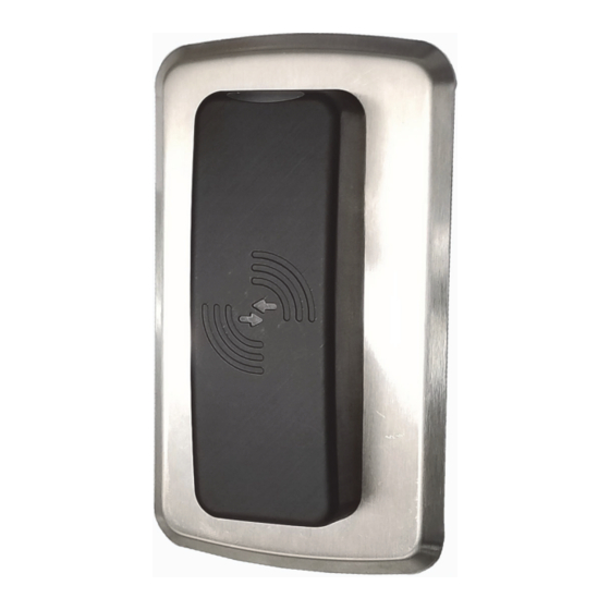
- Page 4 EADER NSTALLATION UIDE DR5000 Readers is designed to work with Transact SA3000 Door Access and third- party Access Control systems that use a Wiegand interface. DR5000 Readers support contactless cards using Near Field Communications (NFC) compatible technology. When a contactless card is within range (1.5 inches or less) from the front of the reader, data on the card is read.
- Page 5 6-20 X .5 PH PHILLIPS SELF DRILLING 044-028-E39 6-32 X 3/4 TRUSS HEAD PHILLIP MACHINE SCREW 044-030-101 M2 STAINLESS STEEL FLAT WASHER 044-059-122 DR5000 WALL MOUNT BRACKET NOTE: A single installation does not use all the hardware included. Figure 1-2 DR5000 Hardware Kit 403-003-001 Rev A...
-
Page 6: Mounting Options
Select mounting-hole size based on chosen fastener for the mounting material. The trim plate is optional and can be ordered separately. The trim plate part number is TRMKT-DR5000. Note: Use appropriate fasteners for the application (#6 x ¾ flathead sheet metal screws are included in hardware kit). - Page 7 3 to pin 4 on terminal block TB2. This identifies the address on the arbitrated bus. Software detects the jumper and responds to the correct poll messages. Plug the terminal block(s) onto the pins of the DR5000 Reader; and the terminal blocks in the proper locations.
- Page 8 D R 5 0 0 0 R E A D E R N S T A L L A T I O N U I D E Secure reader using the tamper resistant security screw (3/32" tamper hex). Hold the top of the reader with one hand and while tightening the screw with the other. Figure 1-4 Figure 1-8 Tamper Resistant Security Screw 403-003-001 Rev A...
-
Page 9: Reader Configuration
The DR5000 Readers have an optical tamper sensor on the back that senses if the reader is removed from the mounting surface or trim plate. This tamper condition is reported on the additional TAMPER output signal (TB2-... -
Page 10: Troubleshooting
If mixing DR5000 and DR4xxx readers in a 2 reader configuration connected to a single Door Controller, one of the readers must always be configured with a jumper. This identifies which reader will answer polls on address 1. -
Page 11: Specifications
D R 5 0 0 0 R E A D E R N S T A L L A T I O N U I D E PECIFICATIONS Physical Size: 1.45"W x 4.0"H x 0.75"D Input Power: 6 - 24VDC 1.4W max Temperature Range: -35 to +66 Celsius Suitable for indoor and outdoor use...
Need help?
Do you have a question about the DR5000 and is the answer not in the manual?
Questions and answers