Advertisement
Quick Links
User Manual
Read this manual before using machine to avoid serious injury and damage
60200PC-WHD
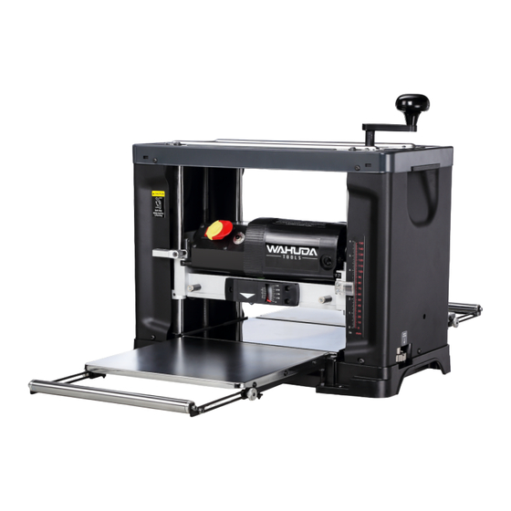
13" 2-Speed Portable Planer
With Spiral Style Cutterhead and -Sided Carbide Inserts
For technical support, email techservices@wahudatools.com or call at 877-568-8879
VER. 05.28.21
Advertisement

Related Manuals for Wahuda 60200PC-WHD

Summary of Contents for Wahuda 60200PC-WHD
- Page 1 User Manual Read this manual before using machine to avoid serious injury and damage 60200PC-WHD 13” 2-Speed Portable Planer With Spiral Style Cutterhead and -Sided Carbide Inserts For technical support, email techservices@wahudatools.com or call at 877-568-8879 VER. 05.28.21...
- Page 2 The drawings, illustrations, photographs, and specifications in this user manual represent your machine at time of print. However, changes may be made to your machine or this manual at any time with no obligation to WAHUDA.
- Page 3 2 - YEAR LIMITED WARRANTY WAHUDA warrants its machinery to be free of defects in workmanship and materials for a period of two (2) years from the date of the original purchase by the original owner. This warranty applies to products sold in United States only.
- Page 4 PRODUCT SPECIFICATIONS 2 Speed Feed - High/ Low 26 FPM / 18 FPM Cutterhead speed RPM 10,000 Motor RPM 23000+/-10% (No Load) Cutterhead diameter 2” Max planer capacity 6" x 13" Max depth of cut @ 6” width 1/8" Max depth of cut @ 13” width 1/16"...
- Page 5 GENERAL SAFETY NOTE: The WARNING! and CAUTION! symbols indicate a potentially hazardous situation which, if not avoided, COULD result in death or serious injury. READ THIS MANUAL completely before assembling and operating this machine. WARNING! TO AVOID serious injury, death, or damage to the machine, please read, understand, and follow, all Safety and Operating Instructions before assembling and operating this machine.
- Page 6 GENERAL SAFETY c ont. ( ) CAUTION! ALWAYS unplug the machine from the electrical receptacle when making adjustments, changing parts or performing any maintenance. AVOID ACCIDENTAL STARTING. Make sure that the power switch is in the “OFF” position before plugging in the power cord to the electrical receptacle. WARNING! AVOID a dangerous working environment.
- Page 7 GENERAL SAFETY c ont. ( ) CAUTION! MAINTAIN your balance. DO NOT extend yourself over the tool. Wear oil resistant rubber soled shoes. Keep floor clear of debris, grease, and wax. MAINTAIN all machines with care. ALWAYS KEEP machine clean and in good working order. KEEP all blades and tool bits sharp.
- Page 8 WARNING! DO NOT handle the plug or planer with wet hands USE only accessories as described in this manual and recommended by WAHUDA. DO NOT pull the planer by the power cord. NEVER allow the power cord to come in contact with sharp edges, hot surfaces, oil or grease.
- Page 9 GROUNDING INSTRUCTIONS WARNING! This machine MUST BE GROUNDED while in use to protect the operator from electric shock. In the event of a malfunction or breakdown, GROUNDING provides the path of least resistance for electric current and reduces the risk of electric shock. The plug MUST be plugged into a matching electrical receptacle that is properly installed and grounded in accordance with ALL local codes and ordinances.
- Page 10 NOTE: Some parts pictured may already be installed on your machine at the factory. Go through the entire manual before contacting WAHUDA. Compare the items to inventory figures and verify that all items are accounted for. If any parts are missing, do not attempt to power on the machine.
- Page 11 IN THE BOX Planer Table Table Extension 4in Dust Port 4ea Star Knob T Torx Handle 2ea long Magnets 2ea Short Magnets 4 to 2 1⁄2 in Adaptor 10 mm combination wrench 8 mm combination wrench 7 mm combination wrench Crank Handle with socket head screw 4 mm allen key m m allen key...
- Page 12 ASSEMBLY WARNING! MAKE CERTAIN THAT THE MACHINE IS DISCONNECTED FROM THE POWER SOURCE. ATTACHING DEPTH ADJUSTMENT CRANK HANDLE Attach the raise/lower adjustment handle to the shaft located on top of the planer and fasten in place with 1 Hex Socket Head screw M5*25, Tighten screw using supplied hex wrench. ATTACHING DUST PORT Facing the rear of the machine, place the outfeed table in the down position.
- Page 13 ASSEMBLY c ont. ( ) TABLE MAGNETS The table magnets keep the tables from falling during transport of the planer. The 2 long table magnets should be attached into the holes on the front of the cutterhead assembly and tightened with the provided nut.
- Page 14 ADJUSTMENTS c ont. ( ) Next, using the metal straight edge in the same 2 locations as above, check to see if the table is coplanar with the wear plate. It should be one continuous flat surface from the outside edge of the table going across the wear plate.
- Page 15 ADJUSTMENTS c ont. ( ) LEVELING INFEED AND OUTFEED PULLOUT EXTENSIONS The table pullout extensions offer the user additional support for longer stock. They must be parallel to, and at the same height as, the table they are attached to. With the infeed table in the down position, loosen the 2 silver knurled extension lock knobs on both sides of the table and pull the extensions to their outward position.
- Page 16 NOTE: Do not get solvent on any painted portion of the machine. WAHUDA spiral cutterheads are machined with a film of oil that may be left over from the process. Removal of this oil residue, if apparent, should be done before you use your new machine.
- Page 17 CLEANING SPIRAL CUTTERHEAD & TIPS (cont.) Separate the tips from the screws and place in separate containers with a bit of mineral spirits or non-chlorinated brake cleaner. Once all are removed, wipe down the bare cutterhead using rags with whichever solvent you chose mentioned above.
- Page 18 OPERATIONS NOTE: This operations section was designed to give instructions on the basic operations of this planer. However, it is in no way comprehensive of every planer operation. It is strongly recommended that you read books, trade magazines, or get formal training to maximize the potential of your planer while minimizing the risks.
- Page 19 OPERATIONS c ont. ( ) 2 - SPEED SELECTOR SWITCH The 26 FPM speed of the 50250PL-WHD planer allows normal speed for production type feed rates. The slower 18 FPM speed allows for a very smooth finish even on figured stock. NOTE: The position of the selector switch may not exactly match the image on the label IMPORTANT NOTE: THE SPEED SELECTOR SWITCH SHOULD ONLY BE SHIFTED FROM ONE SPEED TO ANOTHER WHILE THE MACHINE IS SWITCHED ON (RUNNING) AND NOT PLANING...
- Page 20 OPERATIONS c ont. ( ) POWER SWITCH The planer is turned ON by flipping the switch into the left position and it is turned OFF by flipping the switch to the right. This planer is also equipped with a special lockout toggle switch that prevents unauthorized use.
- Page 21 OPERATIONS c ont. ( ) REPEAT CUT PRESET The Repeat Cut turret style dial indicator, located on the bottom right hand side of the planer, provides a simple way to preset the finished thickness of a workpiece. With the machine powered off, turn the dial indicator to the desired finished thickness.
- Page 22 OPERATIONS c ont. ( ) THICKNESS PLANING Thickness planing sizes the workpiece to a desired thickness, while at the same time creating a smooth and level surface. The thickness of each cut will depend on the type of wood, width of the workpiece, and condition of the lumber (i.e.
- Page 23 OPERATIONS c ont. ( ) GENERAL TIPS AND GUIDELINES Thickness planing always works best when at least one side of the workpiece has a flat surface. If both sides of the workpiece are rough, feed one face of the board through the planer until the entire surface is flat.
- Page 24 MAINTENANCE WARNING! MAKE CERTAIN THAT THE MACHINE IS DISCONNECTED FROM THE POWER SOURCE BEFORE PERFORMING ANY MAINTENANCE PROCEDURES Your planer should provide you with a long time of service provided you take the time to perform the following maintenance operations. CLEANING Sawdust buildup and other debris can cause the tool to plane incorrectly.
- Page 25 MAINTENANCE c ont. ( ) GEAR BOX LUBRICATION The gears in the gear box should be lubricated periodically if necessary. Facing the front of the machine, remove the left side panel. There are 5 screws to remove. Remove the top 2 screws, one in front and one in back, along the top edge of the cover. Remove the 3 socket head screws located around the bottom edge and remove the side panel to expose the gearbox by pulling out on the bottom of the panel.
- Page 26 MAINTENANCE c ont. ( ) BRUSH REPLACEMENT Brush life will vary depending on the load placed on the motor. The brushes should be inspected every 10-15 hours of use. To inspect or replace: Remove the brush holders (A). The other is located in the same position on the rear of the motor assembly.
- Page 27 TROUBLESHOOTING GUIDE...
- Page 28 PARTS...
Need help?
Do you have a question about the 60200PC-WHD and is the answer not in the manual?
Questions and answers