
Subscribe to Our Youtube Channel
Related Manuals for Hoshizaki KM-340MAJ


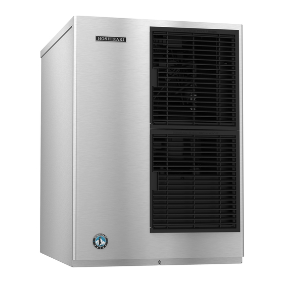
Summary of Contents for Hoshizaki KM-340MAJ
- Page 1 Service Manual Modular Crescent Cuber Models KM-340MAJ, MWJ KM-515MAJ, MWJ, MRJ KM-650MAJ, MWJ, MRJ Number: 73220 hoshizakiamerica.com Issued: 12-18-2017 Revised: 5-13-2021...
- Page 2 Hoshizaki provides this manual primarily to assist qualified service technicians in the service of the appliance. Should the reader have any questions or concerns which have not been satisfactorily addressed, please call, send an e-mail message, or write to the Hoshizaki Technical Support Department for assistance. Phone: 1-800-233-1940; (770) 487-2331 Fax: 1-800-843-1056;...
-
Page 3: Table Of Contents
IMPORTANT This manual should be read carefully before the appliance is serviced. Read the warnings and guidelines contained in this manual carefully as they provide essential information for the continued safe use, service, and maintenance of the appliance. Retain this manual for any further reference that may be necessary. CONTENTS Important Safety Information .................... - Page 4 VI. Preparing the Appliance for Periods of Non-Use ............51 VII. Disposal ......................... 53 VIII. Technical Information ....................54 A. Specification and Performance Data Sheets ............... 54 1. KM-340MAJ ......................54 2. KM-340MWJ ......................55 3. KM-515MAJ ......................56 4. KM-515MWJ ......................57 5.
-
Page 5: Important Safety Information
Important Safety Information Throughout this manual, notices appear to bring your attention to situations which could result in death, serious injury, damage to the appliance, or damage to property. WARNING Indicates a hazardous situation which could result in death or serious injury. - Page 6 WARNING, continued • Children should be properly supervised around this appliance. • Do not climb, stand, or hang on the appliance or allow children or animals to do so. Serious injury could occur or the appliance could be damaged. • Do not use combustible spray or place volatile or flammable substances near the appliance.
-
Page 7: Construction And Water/Refrigeration Circuit Diagram
Water Supply Inlet Spray Tubes Hot Gas Valve Inlet Water Valve Condenser Cleaning Valve Control Switch High-Pressure Splash Guard Switch Check Valve Fan Motor (water) Drier Float Switch Water Pump Control Box Compressor Bin Control and Bracket Model Shown: KM-340MAJ... -
Page 8: Water-Cooled Models (Mwj)
2. Water-Cooled Models (MWJ) Thermostatic Expansion Valve Water Supply Inlet Spray Tubes Hot Gas Valve High-Pressure Switch Inlet Water Valve Water Regulating Valve Condenser Cleaning Valve Control Switch Control Box Splash Guard Check Valve (water) Drier Float Switch Liquid Line Valve Water Pump Compressor Bin Control and Bracket... -
Page 9: Remote Models (Mrj)
3. Remote Models (MRJ) Thermostatic Spray Tubes Expansion Valve Water Supply Inlet Inlet Water Valve Junction Box Evaporator Hot Gas Valve Stainer Cleaning Valve High-Pressure Switch Control Switch Receiver Tank Splash Guard Check Valve (water) Drier Float Switch Liquid Line Valve Water Pump Compressor Control Box... -
Page 10: Water/Refrigeration Circuit Diagram
B. Water/Refrigeration Circuit Diagram 1. Air-Cooled Models (MAJ) Spray Tubes Condenser Inlet Water Valve Drier High-Pressure Evaporator Water Supply Switch Liquid Line Valve (KM-515MAJ and KM-650MAJ) Heat Thermistor Exchanger Suction Line Strainer Water Pump Float Switch Hot Gas Water Valve Tank Discharge Line Compressor... -
Page 11: Water-Cooled Models (Mwj)
2. Water-Cooled Models (MWJ) Water Regulating Valve Condenser Spray Tubes Inlet Water Valve Drier Evaporator Water Supply Liquid Line Valve Heat Thermistor Exchanger High-Pressure Switch Suction Line Strainer Water Pump Float Switch Hot Gas Water Valve Tank Discharge Line Compressor Freeze Pump Out Drain... -
Page 12: Remote Models (Mrj)
3. Remote Models (MRJ) Condenser Headmaster (C.P.R.) Spray Tubes Access Valve Inlet Water Valve Drier Water Supply High-Pressure Receiver Switch Strainer Liquid Line Hot Gas Evaporator Valve Valve Heat Exchanger Thermistor Cleaning Valve Suction Line Water Pump Float Switch Water Tank Discharge Line Compressor... -
Page 13: Sequence Of Operation And Service Diagnosis
II. Sequence of Operation and Service Diagnosis A. Sequence of Operation Flow Chart 1. Operation Flow Chart... -
Page 14: Shutdown Flow Chart
2. Shutdown Flow Chart... -
Page 15: Freeze-Time Correction Chart
3. Freeze-Time Correction Chart... -
Page 16: Service Diagnosis
B. Service Diagnosis WARNING • The appliance should be diagnosed and repaired only by qualified service personnel to reduce the risk of death, electric shock, serious injury, or fire. • Risk of electric shock. Control switch in "OFF" position does not de-energize all loads Use extreme caution and exercise safe electrical practices. - Page 17 1. Sequence and Component Diagnosis 3) Power On: Turn on the power supply, then move the control switch to the "ICE" position. A 5-sec. delay occurs. CB red "POWER OK" LED and CB green "BC CLOSED" LED turn on. If CB yellow "BC OPEN" LED is on (indicating a full bin), check BC. Move ice away from BC actuator paddle.
- Page 18 4) 1-Min. Fill Cycle – LED 4 is on. WV and X11 relay energize. After 1 min., CB checks for a closed FS. If FS is closed, the harvest cycle begins. If harvest cycle begins (Comp, HGV, FMR energized), continue to step 5a. If FS is open, WV remains energized until FS closes (low water safety protection during initial start up and at the end of each harvest).
- Page 19 5b) Harvest Pump Time (Harvest Assist) – LEDs 1, 3, and 2 are on. When the thermistor reaches 48°F (9°C), CB reads 3.9 kΩ from the thermistor and turns harvest termination over to the harvest timer (S4 dip switch 1 & 2 and S5 dip switch 4). When WV de-energizes, LED 4 turns off, X11 relay de-energizes and LED 3 turns on.
- Page 20 a) Freeze Cycle Diagnosis: Confirm Comp, FMR, and PM continue. Confirm that FM and LLV energize. Confirm WRV opens. Next, confirm HGV and X10 relay de-energize. During the first 5 min. of freeze, confirm evaporator is cooling. If not, confirm WV de-energized (not leaking by), HGV de-energized (not bypassing), LLV and FM energize, TXV and HM operate correctly, WRV opens, Comp is efficient, and refrigerant charge is correct.
- Page 21 f) Refrigerant Pressures, HM, and TXV Diagnosis: If evaporator is still not cooling, check refrigerant pressures. See "VIII.A. Specification and Performance Data Sheets." Next, check HM operation. If refrigeration pressures are above HM setpoint and HM is bypassing, replace HM. Check TXV for proper operation. Remove TXV bulb and hold it in your hand, refrigerant low-side pressure should rise, place TXV bulb in ice water, refrigerant low-side pressure should drop.
- Page 22 FM and LLV de-energize. PM stops for 2 sec., then reverses for 10/20 sec. depending on pump-out timer (S4 dip switch 3 & 4) setting. When the pump-out timer terminates, pump-out is complete. The pump-out frequency control (S4 dip switch 5) is factory set, and generally no adjustment is required.
-
Page 23: Freeze-Time Correction Cycle (90 Min.)
C. Freeze-Time Correction Cycle (90 min.) Freeze-Time Correction function is enabled when S4 Dip Switch 7 is in the "ON" position and initiates when the minimum and maximum freeze times have exceeded differential parameters. Freeze-time correction timer and count starts at the beginning of the 2nd freeze cycle after startup from power off condition. - Page 24 2) Freeze-Time Correction Sequence: First occurrence within 36 hr., minimum and maximum freeze times have exceeded differential parameters. CB "POWER OK" LED starts blinking. Freeze-Time Correction Cycle starts. Second occurrence within 36 hr., minimum and maximum freeze times have exceeded differential parameters.
-
Page 25: Control Board Check
D. Control Board Check Before replacing CB that does not show a visible defect and that you suspect is bad, always conduct the following check procedure. This procedure will help you verify your diagnosis. Alarm Reset: If CB is in alarm (beeping), press the "ALARM RESET" button on CB while CB is beeping. -
Page 26: Bin Control Check
E. Bin Control Check 1. Bin Control Check This appliance uses a lever-actuated proximity switch to control the ice level in the storage bin. No adjustment is required. To check BC, follow the steps below. 1) Turn off the power supply. 2) Remove the front panel, then move the control switch to the "OFF"... -
Page 27: Bin Control Cleaning
4) Disconnect BC connector from CB K4 connector, then remove BC from the icemaker. 5) Remove the actuator paddle from the switch mount. See Fig. 2. 6) Wipe down BC with a mixture of 1 part of Hoshizaki "Scale Away" and 25 parts of warm water. Rinse the parts thoroughly with clean water. -
Page 28: Float Switch Check And Cleaning
F. Float Switch Check and Cleaning FS is used to determine that there is sufficient water in the water tank after the 1-min. fill cycle and after each harvest cycle. FS is also used to determine that the appropriate volume of water has been converted into ice before switching out of the freeze cycle. No adjustment is required. -
Page 29: Float Switch Cleaning
6) Wipe down FS housing, shaft, float, and retainer rod with a mixture of 1 part Hoshizaki "Scale Away" and 25 parts warm water. Clean the inside of the rubber boot and hose with cleaning solution. -
Page 30: Thermistor Check
G. Thermistor Check To check thermistor resistance, follow the steps below. 1) Turn off the power supply. 2) Remove the front panel. Move the control switch to the "OFF" position. 3) Remove the control box cover. 4) Remove the thermistor from the refrigerant tubing. 5) Immerse the thermistor sensor portion in a glass containing ice and water for 2 or 3 min. -
Page 31: Diagnostic Tables
I. Diagnostic Tables 1. No Ice Production No Ice Production - Possible Cause 1. Power Supply a) Off, blown fuse, or tripped breaker. b) Not within specifications. 2. Fuse (Control Box) a) Blown. 3. Thermostatic Bin Control a) Tripped with bin filled with ice. See "II.E. - Page 32 2. Freeze-Up Defrost and clean the icemaker prior to diagnosing freeze-up. Fill out a freeze-up checklist. See "II.J. Freeze Up Check List," the Hoshizaki America Technician's Pocket Guide, or contact your local distributor for a copy of the freeze-up checklist.
- Page 33 Freeze-Up - Possible Cause 10. Thermistor a) Loose, disconnected, or defective. See "II.G. Thermistor Check" 11. Thermostatic Expansion Valve a) Defective. 12. Hot Gas Valve a) Closed or restricted. 13. Liquid Line Valve a) Open. Freeze Cycle 1. Evaporator a) Scaled up. b) Damaged.
- Page 34 Low Ice Production - Possible Cause 9. Compressor a) Inefficient or off. 10. Liquid Line Valve a) Erratic or open. 11. Thermostatic Expansion Valve a) Defective. Long Freeze Cycle 1. Evaporator a) Scaled up, dirty. 2. Float Switch a) Scaled up, dirty. See "II.F.
-
Page 35: Freeze-Up Check List
J. Freeze-Up Check List Freeze-Up Check List Please Complete When Diagnosing a Freeze-Up, Refrigerant Leak, or Low Charge Technical Support Fax #: 770-487-3360 Make Copies And Use As Needed Model #___________________________ Serial # ______________________Install Date__________Freeze-Up Date___________ List model and manufacture of bin or dispenser__________________________. Date appliance was last cleaned:__________. -
Page 36: Controls And Adjustments
III. Controls and Adjustments • A Hoshizaki exclusive control board is employed in KM series appliances. • All models are pretested and factory adjusted. • For a control board check procedure, see "II.C. Control Board Check." NOTICE • Fragile, handle very carefully. -
Page 37: Control Board Layout
A. Control Board Layout 1. "J" Control Board "J" Control Board • Bin Control Switch Closed LED (green) • "OUTPUT TEST" Button • S4 Dip Switch • "ALARM RESET" Button (used to test relays on control board) • Bin Control Switch •... -
Page 38: Led Lights And Audible Alarm Safeties
B. LED Lights and Audible Alarm Safeties Beep occurs and red CB "POWER OK" LED turns on when control switch is moved to "ICE" position. Sequence Green LEDs 1 through 4 turn on and sequence from initial startup as listed in the table below. -
Page 39: Settings And Adjustments
Dip switches are factory set. Failure to maintain factory settings may adversely affect performance and warranty coverage. For more information, contact your Hoshizaki Service Center. 1. Default Dip Switch Settings The dip switches are factory-adjusted to the following positionsfor both the 2A7664-01and 2A7664-02 control boards: S4 Dip Switch No. -
Page 40: Harvest Time (S4 Dip Switch 1 & 2)
2. Harvest Time (S4 dip switch 1 & 2) The harvest timer starts counting when the thermistor reaches 48°F (9°C) at the evaporator outlet and the control board reads 3.9 kΩ from the thermistor. The harvest timer is factory set, and generally no adjustment is required. However, a setting longer than the factory setting may be advised in cases where the drain provided at harvest needs to be prolonged for extra cleaning. -
Page 41: Pump-Out Frequency Control (S4 Dip Switch 5)
4. Pump-Out Frequency Control (S4 dip switch 5) The pump-out frequency control is factory set to drain the water tank every 10 cycles. Generally no adjustment is required. However, where water quality is bad and the icemaker needs a pump-out more often, the pump-out frequency can be adjusted. The pump-out frequency control can be set to have a pump-out occur every cycle, or every 10 cycles. -
Page 42: Harvest Pump Time (Harvest Assist)/Freeze-Time Correction (S4 Dip Switch 7)
6. Harvest Pump Time (Harvest Assist)/Freeze-Time Correction (S4 dip switch 7) NOTICE Factory set for proper operation. Do not adjust. Adjustment outside of the factory default setting may result in damage to the appliance. a) Harvest Pump Time (Harvest Assist) Depending on S4 dip switch 7 setting, the pump motor either stays off or is energized during the last seconds of the harvest cycle. -
Page 43: Freeze Timer (S4 Dip Switch 9 & 10)
In this case, see "II.G.3. Low Ice Production" for possible solutions. The freeze timer is factory set and no adjustment is required. Before changing this setting, contact Hoshizaki Technical Support at 1-800-233-1940 for recommendations. -
Page 44: Minimum Harvest Time (S5 Dip Switch 4)
11. Minimum Harvest Time (S5 dip switch 4) NOTICE Factory set for proper operation. Do not adjust. Adjustment outside the factory default setting may result in damage to the appliance. S5 Dip Switch Setting Minimum Harvest Timer No. 4 120 sec. 70 sec. -
Page 45: Refrigeration Circuit And Component Service Information
IV. Refrigeration Circuit and Component Service Information WARNING • This appliance should be diagnosed and repaired only by qualified service personnel to reduce the risk of death, electric shock, serious injury, or fire. • Move the control switch to the "OFF" position and turn off the power supply. Place the disconnect in the "OFF"... - Page 46 2. Brazing WARNING • R-404A itself is not flammable at atmospheric pressure and temperatures up to 176°F (80°C). • R-404A itself is not explosive or poisonous. However, when exposed to high temperatures (open flames), R-404A can be decomposed to form hydrofluoric acid and carbonyl fluoride both of which are hazardous.
- Page 47 Remember to loosen the connection and purge the air from the hose. For the required refrigerant charge, see the rating label inside the icemaker. Hoshizaki recommends only virgin refrigerant or reclaimed refrigerant which meets ARI Standard 700 (latest edition) be used.
-
Page 48: Component Service Information
• The thermistor should be at the 12 o'clock position on the tube. • Smoothly fill the recessed area of the thermistor holder with high thermal conductive type sealant. Hoshizaki America part number 4A0683-01 (Silicone Heat Sink Compound 10-8108 manufactured by GC Electronics), KE-4560 RTV (manufactured by ShinEtsu Silicones), or equivalent are recommended. -
Page 49: Water Regulating Valve Adjustment (Water-Cooled Model)
C. Water Regulating Valve Adjustment (water-cooled model) The water regulating valve is factory set, and generally no adjustment is required. However, when necessary, adjust the water regulator using the following procedure. 1) Prepare a thermometer to check the condenser drain temperature. Attach a pressure gauge to the high-side line of the system. -
Page 50: Maintenance
V. Maintenance The maintenance schedule below is a guideline. More frequent maintenance may be required depending on water quality, the appliance's environment, and local sanitation regulations WARNING • Only qualified service technicians should service the appliance. • To reduce the risk of electric shock, do not touch the control switch or service switch with damp hands •... -
Page 51: Preparing The Appliance For Periods Of Non-Use
VI. Preparing the Appliance for Periods of Non-Use NOTICE • When storing the appliance for an extended time or in sub-freezing temperatures, follow the instructions below to prevent damage. • To prevent damage to the water pump, do not operate the appliance with the control switch in the "WASH"... - Page 52 3. On water-cooled model, remove the water from the water-cooled condenser: 1) Make sure the power supply is off, then remove the front panel and right side panel. 2) Close the condenser water supply line shut-off valve. If connected to a closed loop system, also close the condenser return line shut-off valve.
-
Page 53: Disposal
VII. Disposal The appliance contains refrigerant and must be disposed of in accordance with applicable national, state, and local codes and regulations. Refrigerant must be recovered by properly certified service personnel. -
Page 54: Technical Information
We reserve the right to make changes in specifications and design without prior notice. A. Specification and Performance Data Sheets Pressure data is recorded at 5 min. into freezing cycle. The data not in bold should be used for reference only. 1. KM-340MAJ Specification Sheet AC SUPPLY VOLTAGE 115/60/1 AMPERAGE 9.2 A... -
Page 55: Km-340Mwj
2. KM-340MWJ Specification Sheet AC SUPPLY VOLTAGE 115/60/1 AMPERAGE 7.5 A MINIMUM CIRCUIT AMPACITY 15 A MAXIMUM FUSE SIZE 15 A ELECTRIC & WATER CONSUMPTION 90/70°F 70/50°F ELECTRIC W (kWH/100 lbs.) 690 (4.84) 680 (4.06) WATER gal./24HR (gal./100 lbs.) 62 (18.1) 87 (21.6) WATER COOLED CONDENSER 294 (86) -
Page 56: Km-515Maj
3. KM-515MAJ Specification Sheet AC SUPPLY VOLTAGE 115/60/1 AMPERAGE 10.8 A MINIMUM CIRCUIT AMPACITY 20 A MAXIMUM FUSE SIZE 20 A ELECTRIC & WATER CONSUMPTION 90/70°F 70/50°F ELECTRIC W (kWH/100 lbs.) 990 (5.30) 900 (4.20) WATER gal./24HR (gal./100 lbs.) 72 (16.0) 161 (31.2) ICE PRODUCTION PER CYCLE 10.4 lbs. -
Page 57: Km-515Mwj
4. KM-515MWJ Specification Sheet AC SUPPLY VOLTAGE 115/60/1 AMPERAGE 9.1 A MINIMUM CIRCUIT AMPACITY 20 A MAXIMUM FUSE SIZE 20 A ELECTRIC & WATER CONSUMPTION 90/70°F 70/50°F ELECTRIC W (kWH/100 lbs.) 860 (4.53) 850 (4.13) WATER gal./24HR (gal./100 lbs.) 71 (15.6) 121 (24.4) WATER COOLED CONDENSER 367 (80) -
Page 58: Km-515Mrj With Urc-5F
5. KM-515MRJ with URC-5F Specification Sheet AC SUPPLY VOLTAGE 115/60/1 AMPERAGE 12.8 A MINIMUM CIRCUIT AMPACITY 20 A MAXIMUM FUSE SIZE 20 A ELECTRIC & WATER CONSUMPTION 90/70°F 70/50°F ELECTRIC W (kWH/100 lbs.) 960 (5.10) 900 (4.28) WATER gal./24HR (gal./100 lbs.) 93 (20.5) 196 (39.0) ICE PRODUCTION PER CYCLE... -
Page 59: Km-650Maj
6. KM-650MAJ Specification Sheet AC SUPPLY VOLTAGE 115/60/1 AMPERAGE 14.8 A MINIMUM CIRCUIT AMPACITY 20 A MAXIMUM FUSE SIZE 20 A ELECTRIC & WATER CONSUMPTION 90/70°F 70/50°F ELECTRIC W (kWH/100 lbs.) 1270 (5.41) 1200 (4.57) WATER gal./24HR (gal./100 lbs.) 80 (14.2) 197 (31.2) ICE PRODUCTION PER CYCLE 10.8 lbs. -
Page 60: Km-650Mwj
7. KM-650MWJ Specification Sheet AC SUPPLY VOLTAGE 115/60/1 AMPERAGE 12.6 A MINIMUM CIRCUIT AMPACITY 20 A MAXIMUM FUSE SIZE 20 A ELECTRIC & WATER CONSUMPTION 90/70°F 70/50°F ELECTRIC W (kWH/100 lbs.) 1160 (4.40) 1150 (4.25) WATER gal./24HR (gal./100 lbs.) 96 (15.1) 203 (31.4) WATER COOLED CONDENSER 921 (145) -
Page 61: Km-650Mrj With Urc-5F
8. KM-650MRJ with URC-5F Specification Sheet AC SUPPLY VOLTAGE 115/60/1 AMPERAGE 16.1 A MINIMUM CIRCUIT AMPACITY 20 A MAXIMUM FUSE SIZE 20 A ELECTRIC & WATER CONSUMPTION 90/70°F 70/50°F ELECTRIC W (kWH/100 lbs.) 1230 (5.25) 1150 (4.36) WATER gal./24HR (gal./100 lbs.) 85 (15.0) 191 (30.3) ICE PRODUCTION PER CYCLE... -
Page 62: Wiring Diagrams
B. Wiring Diagrams 1. KM-340M_J... -
Page 63: Km-515M_J And Km-650M_J
2. KM-515M_J and KM-650M_J...
Need help?
Do you have a question about the KM-340MAJ and is the answer not in the manual?
Questions and answers