Chapters
Table of Contents

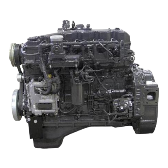
Related Manuals for New Holland 667TA/EEG


Summary of Contents for New Holland 667TA/EEG
- Page 1 ENGINE REPAIR MANUAL 667TA/EEG 667TA/EEC 667TA/EBF 667TA/EED 667TA/EBJ 667TA/EDJ Issued 11-2006 Book/Form Number 87519804 NA Copyright © 2006. CNH America LLC. All Rights Reserved. Printed in U.S.A. • Bur Source Code No. unknown...
- Page 2 All data given in this publication is subject to production variations. Dimensions and weights are only approximate. Illustrations do not necessarily show products in standard condition. For exact information about any particular product, please consult your Dealer Revision History Issue Issue Date Applicable Machine Remarks 667TA/EEG 667TA/EEC 667TA/EBF First Edition 11-2006 87519804 NA 667TA/EED 667TA/EBJ 667TA/EDJ...
-
Page 3: Table Of Contents
ENGINE REPAIR MANUAL ENGINE REPAIR MANUAL TABLE OF CONTENTS CHAPTER 1 DIAGNOSTICS TABLE OF CONTENTS ............. . . 1-1 CNH- EST DIAGNOSTIC TOOL . - Page 4 SECTION 1 - ENGINE REPAIR MANUAL NOTES Issued 11-06 Bur 87519804 NA...
- Page 5 ENGINE REPAIR MANUAL CHAPTER 1 667TA TIER III DIAGNOSTICS Issued 11-2006 Book/Form Number 87519804 NA Copyright © 2006. CNH America LLC. All Rights Reserved. Printed in U.S.A. • Bur Source Code No. unknown...
- Page 6 For exact information about any particular product, please consult your Dealer Revision History Issue Issue Date Applicable Machines Remarks 667TA/EEG 667TA/EEC 667TA/EBF First Edition 11-2006 87519804 NA 667TA/EED 667TA/EBJ 667TA/EDJ 1-II Issued 11-06 Bur...
-
Page 7: Diagnostics
ENGINE REPAIR MANUAL CHAPTER 1 DIAGNOSTICS TABLE OF CONTENTS CNH- EST DIAGNOSTIC TOOL ............. 1-3 TROUBLESHOOTING . - Page 8 ENGINE REPAIR MANUAL CHAPTER 1 - DIAGNOSTICS NOTES Issued 11-06 Bur 87519804 NA...
-
Page 9: Cnh- Est Diagnostic Tool
ENGINE REPAIR MANUAL CHAPTER 1 - DIAGNOSTICS CNH- EST DIAGNOSTIC TOOL BS06K009 Figure 1-1 The EST system allows diagnoses on machines by detecting the operating parameters of electronic control components (control units, sensors etc.) and check flow rates, pressures and temperatures. It is also capable of reading fault codes on the engine. -
Page 10: Troubleshooting
ENGINE REPAIR MANUAL CHAPTER 1 - DIAGNOSTICS TROUBLESHOOTING ENGINE WON’T START Perform the checks described in the Batteries fully charged. Electrical section of the Shop manual. Connections to battery terminals are tight Inspect, clean, tighten or replace and clean. connections. Perform the checks described in the Starter motor working properly. -
Page 11: Engine Overheats
ENGINE REPAIR MANUAL CHAPTER 1 - DIAGNOSTICS ENGINE OVERHEATS Check for leaks, repair leaks and refill to Coolant level correct. proper level. Fan working properly. Replace. Drive belts in serviceable. Replace. Check for leaks, bad bearing, overhaul or Water Pump in working properly. replace. -
Page 12: Engine Lacks Power And Runs Erratically
ENGINE REPAIR MANUAL CHAPTER 1 - DIAGNOSTICS ENGINE LACKS POWER AND RUNS ERRATICALLY Air filter plugged. Clean the filter and replace if necessary. Fuel filters in plugged. Replace. Fuel system working properly. Check and make if necessary repair. Take off the hoses and injection pump, The fuel system shows impurities and or clean and dry thoroughly, then if necessary traces of water. -
Page 13: Engine Exhaust Smoke Black Or Dark Grey
ENGINE REPAIR MANUAL CHAPTER 1 - DIAGNOSTICS ENGINE EXHAUST SMOKE BLACK OR DARK GREY Air filter plugged. Clean the filter and replace if necessary. Check using the Electronic Service Tool Electronic fuel system working properly. (EST) and repair or replace if necessary. Fresh clean diesel fuel in tank. -
Page 14: Engine Knocks Irregularly
ENGINE REPAIR MANUAL CHAPTER 1 - DIAGNOSTICS ENGINE KNOCKS IRREGULARLY Check the following items: Journal play and out-of -roundness, bolt torque for main Knock detected in the crankshaft. journal caps and engine flywheel, oil pressure. Replace the defective parts or overhaul the engine. -
Page 15: Engine Stops
ENGINE REPAIR MANUAL CHAPTER 1 - DIAGNOSTICS ENGINE STOPS Fuel tank filled. Refuel and drain if necessary. Fuel filters plugged. Replace. Check the circuit and make necessary Fuel system in working properly. adjustments or repairs. Valve timing correct. Make necessary adjustments. EXCESSIVE OR INSUFFICIENT OIL PRESSURE Oil pressure control valve working properly. - Page 16 ENGINE REPAIR MANUAL CHAPTER 1 - DIAGNOSTICS NOTES 1-10 Issued 11-06 Bur 87519804 NA...
-
Page 17: 667Ta Engine Overhaul
ENGINE REPAIR MANUAL CHAPTER 2 667TA TIER III 667TA ENGINE OVERHAUL Issued 11-2006 Book/Form Number 87519804 NA Copyright © 2006. CNH America LLC. All Rights Reserved. Printed in U.S.A. • Bur Source Code No. unknown... - Page 18 For exact information about any particular product, please consult your Dealer Revision History Issue Issue Date Applicable Machines Remarks 667TA/EEG 667TA/EEC 667TA/EBF First Edition 11-2006 87519804 NA 667TA/EED 667TA/EBJ 667TA/EDJ 2-II Issued 11-06 Bur...
-
Page 19: Table Of Contents
Cylinder Head Engines: 667TA/EEG - 667TA/EEC ........ - Page 20 ENGINE REPAIR MANUAL CHAPTER 2 - 667TA ENGINE OVERHAUL Idle Speed Control ..............2-38 Overheating Protection .
- Page 21 ENGINE REPAIR MANUAL CHAPTER 2 - 667TA ENGINE OVERHAUL Installing the Tappets and Camshaft ............2-86 CRANKSHAFT .
- Page 22 ENGINE REPAIR MANUAL CHAPTER 2 - 667TA ENGINE OVERHAUL NOTES Issued 11-06 Bur 87519804 NA...
-
Page 23: Engines
ENGINE REPAIR MANUAL CHAPTER 2 - 667TA ENGINE OVERHAUL ENGINES BS06K011 Figure 2-3 BS06K010 Figure 2-1 ENGINES 667TA/EED - 667TAEBF ENGINES: 667TA/EEG - 667TA/EEC BS06K012 Figure 2-2 Figure 2-4 BS06K628 ENGINES 667TA/EED - 667TAEBD ENGINE 667TA/EDJ 87519804 NA Issued 11-06 Bur... -
Page 24: Coding Of Source Engines
ENGINE REPAIR MANUAL CHAPTER 2 - 667TA ENGINE OVERHAUL CODING OF SOURCE ENGINES ENGINE MODEL BREAKDOWN DISCRIPTION Engine Calibration (Power) (D) J= 97 kW (130 H.P.) (E) G= 137 kW (183.7 H.P.) (E) D= 145 kW (194.4 H.P.) (E) C= 148 kW (198.5 H.P.) (B) F= 157 kW (210.5 H.P.) (B) D= 169kW (226.6 H.P.) Compression Ratio... -
Page 25: General Engine Features
ENGINE REPAIR MANUAL CHAPTER 2 - 667TA ENGINE OVERHAUL GENERAL ENGINE FEATURES BS06K013 Figure 2-5 667TA REF. ENGINE TYPE 4- Stroke diesel engine Cycle T.A.A. (Turbo charged, Air to Air cooling) Direct Injection 6 in-line Number of cylinders 104 mm (4.1 inches) Bore 132 mm (5.2 inches) Stroke... - Page 26 ENGINE REPAIR MANUAL CHAPTER 2 - 667TA ENGINE OVERHAUL BS06K014 Figure 2-6 667TA REF. ENGINE TYPE Forced by means of gear pump. Oil psi control valve. Lubrication. 1.2 bar (17.4 psi) Oil pressure with hot engine: at idle rpm. 3.8 bar (55.1 psi) Oil pressure with hot engine: at peak rpm.
-
Page 27: Crank Gear Components And Cylinder Assembly
ENGINE REPAIR MANUAL CHAPTER 2 - 667TA ENGINE OVERHAUL CRANK GEAR COMPONENTS AND CYLINDER ASSEMBLY BS06K015 Figure 2-7 667TA REF. ENGINE TYPE Cylinder liners. 104.000 to 104.024 mm. (4.0945 to 4.0954 in.) Supplied as spares Pistons: Measurement dimension. 49.5 mm. (1.948813 in.) Outer diameter. - Page 28 ENGINE REPAIR MANUAL CHAPTER 2 - 667TA ENGINE OVERHAUL BS06K016 Figure 2-8 667TA REF. ENGINE TYPE 0.30 to 0.40 mm. (0.0118 to 0.0157 in.) Piston ring gaps in cylinder liner. 0.60 to 0.80 mm. (0.0236 to 0.0315 in.) 0.30 to 0.55 mm. (0.0118 to 0.0217 in.) Connecting rod small-end bearing seat.
- Page 29 ENGINE REPAIR MANUAL CHAPTER 2 - 667TA ENGINE OVERHAUL BS06K017 Figure 2-9 667TA REF. ENGINE TYPE Half bearing- journals. Numbers 1, 7 0.044 to 0.106 mm. (0.0017 to 0.0042 in.) Numbers 2, 3, 4, 5, 6 0.041 to 0.103 mm. (0.0016 to 0.0041 in.) Half bearing - crank pins.
-
Page 30: Valve Gear - Cylinder Assembly
ENGINE REPAIR MANUAL CHAPTER 2 - 667TA ENGINE OVERHAUL VALVE GEAR - CYLINDER ASSEMBLY Figure 2-10 BS06K018 667TA REF. ENGINE TYPE Valve guide seats on cylinder head. Ø1= 7.042 to 7.062 mm. (0.2772 to 0.2780 in.) Ø4= 6.970 to 6.999 mm. (0.2744 to 0.2756 in.) Valves - Intake. - Page 31 ENGINE REPAIR MANUAL CHAPTER 2 - 667TA ENGINE OVERHAUL 18 22 BS06K019 Figure 2-11 667TA REF. ENGINE TYPE Valve spring height: Free spring. 47.750 mm. (1.8799 in.) Under load of: 339.8 N ± 19 N (76.4 lbf ± 4.3 lbf). H1= 35.330 mm.
-
Page 32: Torque Specifications
ENGINE REPAIR MANUAL CHAPTER 2 - 667TA ENGINE OVERHAUL TORQUE SPECIFICATIONS PART ............................TORQUE - Nm (lb.-ft.) Cylinder head fastening bolt. 1st phase. Bolts M12x1.75x70 ..................45 to 55 Nm (33.2 to 40.6 lb.-ft.) Bolts M12x1.75x140 ..................35 to 45 Nm (25.8 to 33.2 lb.-ft.) Bolts M12x1.75x180 (pre lubricate with oil) .......... - Page 33 ENGINE REPAIR MANUAL CHAPTER 2 - 667TA ENGINE OVERHAUL Fuel filter bracket M12 bolt........................69 to 85 Nm (50.9 to 62.7 lb.-ft.) M8 bolt........................20 to 28 Nm (14.8 to 20.7 lb.-ft.) Flywheel casing M10 bolt........................75 to 95 Nm (55.3 to 70.1 lb.-ft.) M12 bolt........................
-
Page 34: Special Tools
ENGINE REPAIR MANUAL CHAPTER 2 - 667TA ENGINE OVERHAUL SPECIAL TOOLS 380000158........1-6 Nm dyanametric (torque) screw driver for calibrating injector solenoid valve. connector check nut (Common Rail). 380000665....................Tool for removing the crankshaft front seal. 380000663....................Tool for removing the crankshaft rear seal. 380000671..........................Injector extracting tool. -
Page 35: 667Ta Engines
ENGINE REPAIR MANUAL CHAPTER 2 - 667TA ENGINE OVERHAUL 667TA ENGINES BS06K020 Figure 2-13 1. TURBOCHARGER 5. WATER PUMP 9. FUEL FILTER 2. AUTOMATIC BELT TENSIONER 6. DAMPER FLYWHEEL 10. HIGH PRESSURE PUMP 3. ALTERNATOR 7. OIL PAN (SUMP) 11. COMMON RAIL 4. -
Page 36: Description Of Main Engine Components
ENGINE REPAIR MANUAL CHAPTER 2 - 667TA ENGINE OVERHAUL DESCRIPTION OF MAIN ENGINE COMPONENTS ENGINE BLOCK BS06K021 Figure 2-14 3. SEATS FOR CAMSHAFT BEARINGS AND 1. CYLINDER BORE 5. MAIN BEARING HOUSINGS 7. WATER/OIL COOLER TAPPETS 2. WATER PUMP 4. OIL PUMP 6. -
Page 37: Crankshaft
ENGINE REPAIR MANUAL CHAPTER 2 - 667TA ENGINE OVERHAUL CRANKSHAFT BS06K022 Figure 2-15 1. OIL PUMP DRIVE GEAR 2. CRANKSHAFT 3. TIMING DRIVE GEAR 4. FLYWHEEL ATTACHMENT HUB The crankshaft is made of steel and rests on seven CRANKSHAFT OIL SEALS induction hardened bearing journals. -
Page 38: Connecting Rods
ENGINE REPAIR MANUAL CHAPTER 2 - 667TA ENGINE OVERHAUL CONNECTING RODS Figure 2-16 BS06K023 T h e c o n n e c t i n g r o d s a r e fo r g e d s t e e l , T h e Each connecting rod is marked: •... -
Page 39: Pistons
ENGINE REPAIR MANUAL CHAPTER 2 - 667TA ENGINE OVERHAUL PISTONS BS06K024 Figure 2-17 The piston crown features a high turbulence The following reference data is engraved into the combustion chamber. The underside of the piston piston crown: crown is cooled by engine oil delivered by a spray 1. -
Page 40: Egr Exhaust Gas Recirculation System
ENGINE REPAIR MANUAL CHAPTER 2 - 667TA ENGINE OVERHAUL CAMSHAFT Figure 2-18 BS06K025 BS06K026 Figure 2-19 A. INTAKE VALVE LOBE B. EXHAUST VALVE LOBE C. EGR LOBE The cam shaft is installed on 7 journals in the engine The exhaust gas recirculation system (EGR), lowers block. -
Page 41: Valve Control
ENGINE REPAIR MANUAL CHAPTER 2 - 667TA ENGINE OVERHAUL VALVE CONTROL BS06K027 Figure 2-20 1. ROCKER ARM 3. PUSH ROD 5. SPRING SEAT 7. CAMSHAFT 9. VALVE BRIDGE 2. ADJUSTER SCREW 4. VALVE SPRING RETAINER (KEEPERS) 6. SPRING 8. TAPPET 10. -
Page 42: Cylinder Head Engines: 667Ta/Ebf - 667Ta/Ebd - 667Ta/Eed
ENGINE REPAIR MANUAL CHAPTER 2 - 667TA ENGINE OVERHAUL CYLINDER HEAD ENGINES: 667TA/EBF - 667TA/EBD - 667TA/EED BS06K028 Figure 2-21 CYLINDER HEAD FOR ENGINES 667TA/EBF - 667TA/EBD - 667TA/EED 1. EXHAUST MANIFOLD 3. THERMOSTAT 5. GRID HEATER 2. INJECTOR 4. VALVE SEAT 6. -
Page 43: Cylinder Head Engines: 667Ta/Eeg - 667Ta/Eec
ENGINE REPAIR MANUAL CHAPTER 2 - 667TA ENGINE OVERHAUL CYLINDER HEAD ENGINES: 667TA/EEG - 667TA/EEC BS06K029 Figure 2-22 1. EXHAUST MANIFOLD 3. THERMOSTAT 5. SUPPORT WITH WIRING HARNESS 7. INTAKE MANIFOLD 2. INJECTOR 4. VALVE SEAT 6. GRID HEATER T h e c a s t i r o n c y l i n d e r h e a d i s m a c h i n e d t o... -
Page 44: Cylinder Head Engine: 667Ta/Edj
ENGINE REPAIR MANUAL CHAPTER 2 - 667TA ENGINE OVERHAUL CYLINDER HEAD ENGINE: 667TA/EDJ BS06K136 Figure 2-23 1. EXHAUST MANIFOLD 3. THERMOSTAT 5. SUPPORT WITH WIRING HARNESS 7. INTAKE MANIFOLD 2. INJECTOR 4. VALVE SEAT 6. GRID HEATER T h e c a s t i r o n c y l i n d e r h e a d i s m a c h i n e d t o The cylinder head is also fitted for the following accommodate the following parts: components to be inserted on to the head. -
Page 45: Valves And Valve Seats
ENGINE REPAIR MANUAL CHAPTER 2 - 667TA ENGINE OVERHAUL VALVES AND VALVE SEATS Figure 2-24 BS06K030 1. INTAKE VALVE 3. INTAKE SIDE 2. EXHAUST VALVE 4. EXHAUST SIDE Valve seats have the following angles: Exhaust valves- 45° BS06K032 Figure 2-26 Intake valves- 60°... -
Page 46: Engine Head Machining
Equal position of fastening bolt holes (2) allows it to be installed in any position. BS06K036 Figure 2-31 ENGINES: 667TA/EBF - 667TAEED BS06K035 Figure 2-29 ENGINES: 667TA/EEG - 667TA/EEC BS06K629 Figure 2-32 ENGINE: 667TA/EDJ 2-28 Issued 11-06 Bur 87519804 NA... -
Page 47: Accessory Equipment Drive
ENGINE REPAIR MANUAL CHAPTER 2 - 667TA ENGINE OVERHAUL ACCESSORY EQUIPMENT DRIVE BS06K038 Figure 2-33 1. AUTOMATIC BELT TENSIONER 2. ALTERNATOR 3. POLY-V-BELT 4. WATER PUMP 5. CRANKSHAFT A Poly-V-belt (3) transmits the rotation of the crankshaft (5) to water pump (4) and to the alternator (2). -
Page 48: Engine Lubrication
4. OIL / WATER COOLER A. OIL PAN: 667TA/EED - 667TA/EBD C. PRESSURIZED OIL PATH B. OIL PAN:667TA/EEG -667TA/EEC -667TA/EBF - 667TA/EED - 667TA/EDJ D. GRAVITY OIL RETURN PATH Pressur ized lubr ication is with the fo llowing components: Gerotor oil pump (5) housed in the front of the engine block, driven by the spur tooth gear force fitted on the crankshaft;... -
Page 49: Oil Cooler
1. HEAT EXCHANGER BODY 3. WATER / OIL COOLER 5. OIL RETURN TO FILTER* 7. OIL FILTER 2. INNER GASKET 4. GASKET (BETWEEN COOLER AND ENGINE BLOCK) 6. OIL FLOW FROM FILTER* * Only engines: 667TA/EEG - 667TA/EEC. BY-PASS VALVE OIL PRESSURE CONTROL VALVE BS06K042 Figure 2-37 A. -
Page 50: Oil Pump
ENGINE REPAIR MANUAL CHAPTER 2 - 667TA ENGINE OVERHAUL OIL PUMP OIL PAN (SUMP) ENGINES: 667TA/EEG- 667TA/EEC- 667TA/EBF- 667TA/EED- 667TA/EDJ Figure 2-40 BS06K045 OIL PAN GASKET INSTALLATION BS06K043 Figure 2-38 OIL PUMP Figure 2-41 BS06K046 STEEL OIL PAN (SUMP) BS06K044 Figure 2-39 1.-Crankshaft with oil pump drive gear... -
Page 51: Oil Pan (Sump) Engines: 667Ta/Eed
ENGINE REPAIR MANUAL CHAPTER 2 - 667TA ENGINE OVERHAUL OIL PAN (SUMP) ENGINES: 667TA/EED- 667TA/EBD BS06K047 Figure 2-42 CAST IRON OIL PAN (SUMP) The cast iron oil pan (sump) is fastened to the engine block by bolts with interposed flat washers and a thin gasket. -
Page 52: Engine Oil Vapor Recirculation
ENGINE REPAIR MANUAL CHAPTER 2 - 667TA ENGINE OVERHAUL ENGINE OIL VAPOR RECIRCULATION BS06K048 Figure 2-43 1. PRE-SEPARATOR 3. BLOW-BY FILTER A. OIL CONDENSATE 2. RECIRCULATION TO INTAKE 4. RETURN TO ENGINE B. OIL VAPORS BLOW-BY RECIRCULATION In blow-by filter (3) a portion of the vapors partially condense and return to the oil pan (sump) through The rocker cover has a blow-by pre-separator (1), line (4), while the remaining is recirculated to the... -
Page 53: Engine Cooling
ENGINE REPAIR MANUAL CHAPTER 2 - 667TA ENGINE OVERHAUL ENGINE COOLING Figure 2-44 BS06K049 1. OIL COOLER 3. THERMOSTAT B. WATER RECIRCULATING IN ENGINE 2. WATER PUMP A. WATER FROM THERMOSTAT OUTLET C. WATER TO PUMP INLET • Thermostat, used to regulate coolant flow. The engine cooling system is a closed circuit circulation type and is made up of the following components:... -
Page 54: Water Pump
A. STROKE STARTS AT 96° C (204° F) ≥ 7.5MM (.30 IN). WATER PUMP Thermostat opening for engines: 667TA/EEG, EEC, EBF, EED, EBD= 79 to 83° C (174 to 181° F). 667TA/EDJ= 83 to 98° C (181 to 208° F). -
Page 55: High Pressure Electronic Injection System (Common Rail)
ENGINE REPAIR MANUAL CHAPTER 2 - 667TA ENGINE OVERHAUL HIGH PRESSURE ELECTRONIC INJECTION SYSTEM (COMMON RAIL) BS06K053 Figure 2-48 1. HARNESS TO INJECTORS 5. CRANKSHAFT SENSOR 9. CAMSHAFT SENSOR 2. ELECTRO- INJECTOR 6. EDC7UC31 CONTROL UNIT 10. FUEL PRESSURE SENSOR 3. -
Page 56: Edc7Uc31 -Electronic Control Unit Operation
ENGINE REPAIR MANUAL CHAPTER 2 - 667TA ENGINE OVERHAUL EDC7UC31 -ELECTRONIC CONTROL MAXIMUM ENGINE SPEED LIMITING UNIT OPERATION Depending on the application, the control unit memory can contain appropriate engine speed limits. ENGINE PREHEATING ELEMENT CONTROL When the engine speed surpasses these limits, the control unit activates power reduction by controlling Pre-post heating is activated when even just one of tur n on time of the electro-injectors. -
Page 57: Recover Strategies
ENGINE REPAIR MANUAL CHAPTER 2 - 667TA ENGINE OVERHAUL RECOVER STRATEGIES • Control of fuel leaks. In the case of fuel supply problems, the system controls the engine with suitable constant power values obtained with a low number of rev and high torque values in order to inject the maximum quantity of fuel. -
Page 58: Fuel Supply System
ENGINE REPAIR MANUAL CHAPTER 2 - 667TA ENGINE OVERHAUL FUEL SUPPLY SYSTEM BS06K054 Figure 2-49 7. LOW PRESSURE GEAR TYPE 1. ELECTRO-INJECTOR 4. PRE-FILTER B. LOW PRESSURE CHARGE PUMP 5. COMMON RAIL PRESSURE RELIEF 2. COMMON RAIL 8. HIGH PRESSURE PUMP C. -
Page 59: Fuel Supply System Diagram
ENGINE REPAIR MANUAL CHAPTER 2 - 667TA ENGINE OVERHAUL FUEL SUPPLY SYSTEM DIAGRAM BS06K055 Figure 2-50 17. MECHANICAL ROTOR PUMP 1. HIGH PRESSURE PUMP 9. EDC7UC31 CONTROL UNIT HEAT EXCHANGER BY-PASS CHECK VALVE 2. LOW PRESSURE REGULATOR VALVE 18. ROTOR PUMP PRESSURE 10. -
Page 60: Fuel Filter
ENGINE REPAIR MANUAL CHAPTER 2 - 667TA ENGINE OVERHAUL FUEL FILTER BS06K056 Figure 2-51 1. FUEL FILTER BRACKET A. OUTLET CONNECTION TO HIGH PRESSURE PUMP 2. FUEL HEATER CONNECTOR B. COMMON RAIL, CYLINDER HEAD INJECTORS DISCHARGE LINE INLET CONNECTION 3. ELECTRIC FUEL HEATER C. -
Page 61: Mechanical Supply Pump- Normal Operating Condition
ENGINE REPAIR MANUAL CHAPTER 2 - 667TA ENGINE OVERHAUL MECHANICAL SUPPLY PUMP- NORMAL OPERATING CONDITION BS06K057 Figure 2-52 1. PRESSURE SAFETY VALVE A. FUEL INLET FROM TANK 2. PRIMING BY-PASS VALVE IN CLOSED POSITION B. FUEL OUTLET TO FILTER The charge gear pump, installed on the rear of the The feed pump is driven by the high pressure pump high pressure pump, draws fuel from the tank shaft. -
Page 62: Fuel System Bleeding
ENGINE REPAIR MANUAL CHAPTER 2 - 667TA ENGINE OVERHAUL FUEL SYSTEM BLEEDING BS06K059 Figure 2-54 1. PRESSURE SAFETY VALVE A. FUEL INLET FROM TANK 2. PRIMING BY-PASS VALVE IN CLOSED POSITION B. FUEL OUTLET TO FILTER The by-pass valve (2) opens when, the engine is When activating the hand pump the by-pass valve (2) turned off. -
Page 63: High Pressure Pump Type Cp3.3
ENGINE REPAIR MANUAL CHAPTER 2 - 667TA ENGINE OVERHAUL HIGH PRESSURE PUMP TYPE CP3.3 BS06K060 Figure 2-55 HIGH PRESSURE PUMP 1. FUEL OUTLET CONNECTION TO RAIL 2. HIGH PRESSURE PUMP 3. HIGH PRESSURE REGULATOR 4. FUEL INLET CONNECTION FROM FILTER 5. - Page 64 ENGINE REPAIR MANUAL CHAPTER 2 - 667TA ENGINE OVERHAUL BS06K061 Figure 2-56 EXPLODED VIEW OF HIGH PRESSURE PUMP 4. INDIVIDUAL HIGH PRESSURE PUMP 7. HIGH PRESSURE PUMP FUEL 1. MECHANICAL GEAR CHARGE FEED PUMP PLUNGER (1 OF 3) INLET FROM FILTER 8.
-
Page 65: High Pressure Pump Inside Structure
ENGINE REPAIR MANUAL CHAPTER 2 - 667TA ENGINE OVERHAUL HIGH PRESSURE PUMP INSIDE STRUCTURE BS06K161 Figure 2-59 BS06K160 Figure 2-57 BS06K159 Figure 2-60 BS06K158 Figure 2-58 1. CYLINDER 5. PISTON 2. THREE LOBE ELEMENT 6. PUMP SHAFT 3. CAP INTAKE VALVE 7. -
Page 66: Operating Principal
ENGINE REPAIR MANUAL CHAPTER 2 - 667TA ENGINE OVERHAUL OPERATING PRINCIPAL BS06K063 Figure 2-61 BS06K160 Figure 2-62 7. HIGH PRESSURE 1. OUTLET FOR RAIL DELIVERY LINE 3. HIGH PRESSURE PLUNGER 5. PLUNGER SUPPLY PASSAGE REGULATOR 6. PRESSURE REGULATOR 2. RAIL DELIVERY VALVE 4. -
Page 67: Theory Of Operation
ENGINE REPAIR MANUAL CHAPTER 2 - 667TA ENGINE OVERHAUL Figure 2-64 BS06K065 BS06K064 Figure 2-63 1. FUEL EXHAUST FLUE 1. INLET TO HIGH PRESSURE PLUNGERS 2. FUEL EXHAUST FLOWING FROM PUMP WITH 2. PUMP LUBRICATION PASSAGES CONNECTOR TO HIGH PRESSURE LINE FOR 3. -
Page 68: Common Rail
ENGINE REPAIR MANUAL CHAPTER 2 - 667TA ENGINE OVERHAUL When the pumping element chamber pressure The pump is lubricated and cooled by the fuel. becomes less than the supply pressure, the intake The pump replacement time on the engine is highly valve is again opened and the cycle is repeated. -
Page 69: Common Rail Pressure Relief Valve
ENGINE REPAIR MANUAL CHAPTER 2 - 667TA ENGINE OVERHAUL COMMON RAIL PRESSURE RELIEF VALVE BS06K067 Figure 2-66 COMMON RAIL PRESSURE RELIEF VALVE 1. DIRECT TANK DISCHARGE 3. BODY 5. SMALL PISTON 2. STOP 4. SPRING 6. SEAT ON RAIL A. NORMALLY, THE TAPERED PISTON (5) END STAYS CLOSED THE DISCHARGE IS DIVERTED TO THE FUEL TANK. -
Page 70: Electro-Injector
ENGINE REPAIR MANUAL CHAPTER 2 - 667TA ENGINE OVERHAUL ELECTRO-INJECTOR BS06K069 Figure 2-68 BS06K068 Figure 2-67 INJECTION START INJECTOR IN REST POSITION When coil (4) is energized, it makes ball shutter (6) move upwards. The control volume (9) fuel flows 1. -
Page 71: Electro-Injector
1. JET Pressures Injectors Engines Minimal operating pressure Nominal operating pressure CRIN 1 not available 667TA/EEG - 667TA/EEC not available not available CRIN 2 DLLA 137 PV 3 667TA/EBF - 667TA/EBD 250 bar (3626 psi.) 1600 bar (23206 psi.) CRIN 2... -
Page 72: Pressure Limiter For Fuel Return
ENGINE REPAIR MANUAL CHAPTER 2 - 667TA ENGINE OVERHAUL PRESSURE LIMITER FOR FUEL RETURN Figure 2-70 BS06K071 A. TO FUEL TANK B. FROM INJECTORS The pressure limiter for the fuel return is housed on the rear of the cylinder head, and adjusts the pressure of the fuel returning from injectors at a pressure of 1.3 to 2.0 bars (18.9 to 29 psi.). -
Page 73: Location Of The Main Electrical Components
ENGINE REPAIR MANUAL CHAPTER 2 - 667TA ENGINE OVERHAUL LOCATION OF THE MAIN ELECTRICAL COMPONENTS BS06K072 Figure 2-71 1. COOLANT TEMPERATURE SENSOR 7. SOLENOID VALVE FOR PRESSURE REGULATOR 2. ELECTRO-INJECTOR 8. FUEL TEMPERATURE SENSOR 3. FUEL RAIL PRESSURE SENSOR 9. EDC7UC31 ELECTRONIC CONTROL UNIT 4. -
Page 74: Edc7Uc31 Electronic Control Unit
ENGINE REPAIR MANUAL CHAPTER 2 - 667TA ENGINE OVERHAUL EDC7UC31 ELECTRONIC CONTROL UNIT BS06K073 Figure 2-72 EDC7UC31 ELECTRONIC CONTROL UNIT A. CONNECTOR TO INJECTORS B. CONNECTOR FOR POWER INPUT AND FUNCTIONS PROVIDED FOR IN THE APPLICATION C. CONNECTOR TO SENSORS 2-56 Issued 11-06 Bur 87519804 NA... -
Page 75: Cabling Connector Pinout On Engine
ENGINE REPAIR MANUAL CHAPTER 2 - 667TA ENGINE OVERHAUL CABLING CONNECTOR PINOUT ON ENGINE BS06K074 Figure 2-73 CONNECTOR / CABLING DIAGRAM A. CONNECTOR A (INJECTORS) EDC7UC31 ECU (POWER) 5. CAMSHAFT SENSOR B. CONNECTOR B NOT SHOWN (SEE NOTE BELOW) 6. OIL PRESSURE AND TEMPERATURE SENSOR C. -
Page 76: Connector (A) Injectors Pinout Diagram
ENGINE REPAIR MANUAL CHAPTER 2 - 667TA ENGINE OVERHAUL CONNECTOR (A) INJECTORS PINOUT DIAGRAM CONNECTOR (C) SENSORS PINOUT DIAGRAM EDC7UC31 EDC7UC31 FUNCTION FUNCTION ECU PIN ECU PIN Cylinder 5 injector Not Used Cylinder 6 injector Not Used Cylinder 4 injector Not Used Cylinder 1 injector Not Used... -
Page 77: Crankshaft Sensor
ENGINE REPAIR MANUAL CHAPTER 2 - 667TA ENGINE OVERHAUL CRANKSHAFT SENSOR BS06K075 Figure 2-74 CRANKSHAFT SENSOR The crankshaft sensor is an inductive sensor located The crankshaft sensor is connected to the at the front left hand side of the engine. The EDC -7 control unit on pins 19C - 23C. -
Page 78: Boost Temperature - Pressure Sensor
ENGINE REPAIR MANUAL CHAPTER 2 - 667TA ENGINE OVERHAUL BOOST TEMPERATURE - PRESSURE SENSOR This component incorporates a temperature sensor and a pressure sensor all in one unit. I n s t a l l e d o n t h e i n t a ke m a n i fo l d , t h e s e n s o r measures the temperature and boost pressure, which serves to make an accurate calculation of the quantity of fuel to be injected in each cycle. -
Page 79: Common Rail Fuel Pressure Sensor
ENGINE REPAIR MANUAL CHAPTER 2 - 667TA ENGINE OVERHAUL COMMON RAIL FUEL PRESSURE SENSOR BS06K079 Figure 2-78 COMMON RAIL FUEL PRESSURE SENSOR CONNECTOR Reference Description EDC7UC31 control unit pin Ground Signal Power supply The fuel rail pressure sensor is installed on one end This sensor is connected to the EDC7UC31 control of the common rail, this sensor measures the internal unit on pins 12C - 14C - 13C. -
Page 80: Electro-Injectors
ENGINE REPAIR MANUAL CHAPTER 2 - 667TA ENGINE OVERHAUL ELECTRO-INJECTORS BS06K080 Figure 2-79 INJECTOR WIRE HARNESS LAYOUT BS06K081 Figure 2-80 INJECTOR WIRE HARNESS The electro-injectors are a normally Closed (N.C.) The impedance of the coil of each injector is 0.56 - solenoid valve. -
Page 81: Intake Air Pre-Post Resistance Heater And Relay
ENGINE REPAIR MANUAL CHAPTER 2 - 667TA ENGINE OVERHAUL INTAKE AIR PRE-POST RESISTANCE HEATER AND RELAY BS06K083 Figure 2-82 GRID PLATE HEATER CONTROL RELAY The control relay is connected to the EDC7UC31 control unit B connector. Figure 2-81 BS06K082 T h e r e l ay i s t r i p p e d w i t h w a t e r a n d o r f u e l temperature below 5°... -
Page 82: Coolant Temperature Sensor
ENGINE REPAIR MANUAL CHAPTER 2 - 667TA ENGINE OVERHAUL COOLANT TEMPERATURE SENSOR BS06K209 Figure 2-83 COOLANT TEMPERATURE SENSOR The coolant temperature sensor is a variable r e s i s t a n c e s e n s o r a b l e t o r e a d t h e c o o l a n t temperature in order to provide the EDC7UC31 control unit with an indication of the temperature status of the engine. -
Page 83: Fuel Temperature Sensor
ENGINE REPAIR MANUAL CHAPTER 2 - 667TA ENGINE OVERHAUL FUEL TEMPERATURE SENSOR This sensor detects the fuel temperature so the EDC7UC31 control unit can precisely inject the fuel required. The fuel temperature sensor is connected to the EDC7UC31 control unit on pins 35C - 18C. T h e s e n s o r i m p e d a n c e a t 2 0 °... -
Page 84: High Pressure Pump - Pressure Regulator
ENGINE REPAIR MANUAL CHAPTER 2 - 667TA ENGINE OVERHAUL HIGH PRESSURE PUMP - PRESSURE REGULATOR BS06K212 Figure 2-86 Delivery pressure to the common rail is modulated A. PRESSURE REGULATOR between 250 and 1600 bar (3626 and 23206 psi) by The quantity of fuel supplied to the high pressure the EDC7UC31 control unit by controlling the high pump is controlled by the supply pressure regulator pressure regulator solenoid valve. -
Page 85: Checking The Fuel System
ENGINE REPAIR MANUAL CHAPTER 2 - 667TA ENGINE OVERHAUL CHECKING THE FUEL SYSTEM LOW PRESSURE SUPPLY TEST BS06K214 Figure 2-87 DIAGRAM OF SET UP OF COMPONENTS FOR SPECIFIC TEST 1. FUEL TANK 6. HIGH PRESSURE PUMP 11. M1 PRESSURE GAUGE 0-15 BAR FUEL FILTER INLET 2. -
Page 86: Low -Pressure Pump
ENGINE REPAIR MANUAL CHAPTER 2 - 667TA ENGINE OVERHAUL LOW -PRESSURE PUMP BS06K216 Figure 2-89 The function of the gear pump is to supply the high After starting the engine, check the pressure at 1500 pressure pump. It is driven by the shaft of the high rpm. -
Page 87: Test On The Pressure Relief Valve On The Common Rail
ENGINE REPAIR MANUAL CHAPTER 2 - 667TA ENGINE OVERHAUL TEST ON THE PRESSURE RELIEF VALVE ON THE COMMON RAIL BS06K217 Figure 2-90 The pressure relief valve is installed on the end of the If the valve seeps diesel without a fault code, then common rail, its function is to protect the systems replace the valve. -
Page 88: Test On Fuel Backflow From The Return
ENGINE REPAIR MANUAL CHAPTER 2 - 667TA ENGINE OVERHAUL TEST ON FUEL BACKFLOW FROM THE RETURN Figure 2-92 BS06K219 BS06K218 Figure 2-91 1. INJECTOR DUCT LOCKING NUT Tests on fuel backflow from the return establishes When the EDC7UC31 control unit warning light the operating status of the injectors. - Page 89 ENGINE REPAIR MANUAL CHAPTER 2 - 667TA ENGINE OVERHAUL BS06K220 Figure 2-93 Proceed with the injector fuel backflow tests as The defective injector is the one when plugged follows: causes a significant reduction in recirculated fuel. • Remove the duct (1) from the cylinder head. NOTE: When changing an injector it is necessary to •...
-
Page 90: Engine Overhaul On The Bench
ENGINE REPAIR MANUAL CHAPTER 2 - 667TA ENGINE OVERHAUL ENGINE OVERHAUL ON THE BENCH IMPORTANT: Push clamp (1), as shown in figure B to disconnect the low pressure fuel lines (2, 3, 4) from corresponding connections. After DISASSEMBLING THE ENGINE disconnecting the line, reset the clamp (1) in locking STEP 1 position figure A to prevent distortion to the clamp. - Page 91 ENGINE REPAIR MANUAL CHAPTER 2 - 667TA ENGINE OVERHAUL STEP 6 Figure 2-98 BS06K225 9. FUEL HEATER- TEMPERATURE 1. INJECTOR CONNECTIONS 5. CRANKSHAFT SPEED SENSOR SENSOR 2. ENGINE COOLANT TEMPERATURE SENSOR 6. INJECTOR 10. HIGH PRESSURE REGULATOR 7. BOOST TEMPERATURE-PRESSURE 3.
- Page 92 ENGINE REPAIR MANUAL CHAPTER 2 - 667TA ENGINE OVERHAUL STEP 8 STEP 10 BS06K229 Figure 2-102 BS06K227 Figure 2-100 Loosen tappet adjusting nuts (1) and unscrew the Disconnect line (2) from fuel return pressure limiter adjusters. (1) as shown in step 3 page 2-72. Remove the bolts (2), remove the rocker assembly Remove the nut, loosen the retainer collar and (3), consisting of bracket (6), rockers (4), shafts (5)
- Page 93 ENGINE REPAIR MANUAL CHAPTER 2 - 667TA ENGINE OVERHAUL STEP 12 STEP 14 BS06K231 Figure 2-104 BS06K233 Figure 2-106 Remove shroud (5), if present from turbocharger (1). Remove bolts (1) and disconnect intake manifold and Disconnect oil line (3) from heat exchanger oil filter heater air shroud (2).
- Page 94 ENGINE REPAIR MANUAL CHAPTER 2 - 667TA ENGINE OVERHAUL STEP 17 STEP 19 BS06K236 Figure 2-109 BS06K238 Figure 2-111 Release the drive belt tensioner (2) and remove the Remove the bolts and disconnect the EDC7UC31 belt (3) from the pulleys. Then remove the belt control unit (1), including the heat exchanger.
- Page 95 ENGINE REPAIR MANUAL CHAPTER 2 - 667TA ENGINE OVERHAUL STEP 22 STEP 24 BS06K241 Figure 2-114 BS06K243 Figure 2-116 Remove the bolts (3) and take off the damping Place Special Tool 380000665 (4) to the front of the flywheel (2) and the pulley (1). crankshaft (2).
- Page 96 ENGINE REPAIR MANUAL CHAPTER 2 - 667TA ENGINE OVERHAUL STEP 26 STEP 29 BS06K245 Figure 2-118 BS06K248 Figure 2-121 Remove the bolts and take off the front cover (1). Screw two pins (2) of adequate length into the crankshaft holes (3). IMPORTANT: Note the installation position of the bolts because they are different lengths.
- Page 97 BS06K252 Figure 2-125 NOTE: Only on engines 667TA/EED- /EBD. BS06K250 Figure 2-123 NOTE: Only on engines 667TA/EEG- /EEC- /EBF- Remove bolts and oil pan (sump) (1). /EED- /EDJ. STEP 34 Remove the bolts, plate (2) and oil pan (sump) (1).
- Page 98 ENGINE REPAIR MANUAL CHAPTER 2 - 667TA ENGINE OVERHAUL STEP 36 STEP 38 BS06K255 Figure 2-128 BS06K257 Figure 2-130 Remove bolts and take off timing gear case (1). Remove bolts (1) and take off the main bearing journals(2). IMPORTANT: Note the installation position of the bolts because they are different lengths.
- Page 99 ENGINE REPAIR MANUAL CHAPTER 2 - 667TA ENGINE OVERHAUL STEP 40 STEP 42 BS06K261 Figure 2-134 Remove bolts and take off camshaft (2), retaining BS06K259 Figure 2-132 plate (1). Remove crankshaft (2) from crankcase by means of a suitable tool (1) and a hoist. IMPORTANT: Note plate (1) mounting position.
-
Page 100: Checks And Specifications On Engine Crankcase
ENGINE REPAIR MANUAL CHAPTER 2 - 667TA ENGINE OVERHAUL CHECKS AND SPECIFICATIONS ON ENGINE CRANKCASE CHECKS AND MEASUREMENTS STEP 46 STEP 45 BS06K265 Figure 2-138 Measurements must be taken for each cylinder, at three different heights (1,2,3) of the bore and on two BS06K264 Figure 2-137 planes perpendicular to each other. -
Page 101: Checking The Eccentric Lift And Bearing Surface
ENGINE REPAIR MANUAL CHAPTER 2 - 667TA ENGINE OVERHAUL CHECKING THE ECCENTRIC LIFT AND BEARING BEARINGS SURFACE STEP 48 STEP 47 Figure 2-140 BS06K267 The camshaft bearings (2) must be force-fitted into BS06K266 Figure 2-139 their respective seats. Check camshaft with a micrometer (1) the bearing surface (2) measurement must not have greater than The inner surfaces must show no traces of seizing or 0.04 mm (0.0016 in.) of wear otherwise replace... -
Page 102: Checking The Crankcase Cylinder Head Mating Surface
ENGINE REPAIR MANUAL CHAPTER 2 - 667TA ENGINE OVERHAUL STEP 49 CHECKING THE CRANKCASE CYLINDER HEAD MATING SURFACE STEP 50 BS06K270 Figure 2-143 Verify that the crankcase cylinder head mating surface does not show any warping. This check can be accomplished by taking out dowels (4), with a straight edge (2) and a thickness gauge (3). -
Page 103: Camshaft Timing
ENGINE REPAIR MANUAL CHAPTER 2 - 667TA ENGINE OVERHAUL CAMSHAFT TIMING STEP 51 BS06K271 Figure 2-144 MAIN FEATURES OF CAMSHAFT The shaft support journals and lobe surfaces must be perfectly smooth. If they show signs of seizing and scoring, replace the camshaft and respective bearings. -
Page 104: Installing The Tappets And Camshaft
ENGINE REPAIR MANUAL CHAPTER 2 - 667TA ENGINE OVERHAUL INSTALLING THE TAPPETS AND CAMSHAFT STEP 55 STEP 53 BS06K276 Figure 2-149 Place camshaft (1), retaining plate (2) with the slotted hole facing the engine block upper side and the Figure 2-147 BS06K274 stamping facing the operator, then tighten bolts to the Lubricate tappets (1) and install them into their... -
Page 105: Crankshaft
ENGINE REPAIR MANUAL CHAPTER 2 - 667TA ENGINE OVERHAUL CRANKSHAFT If any signs of seizing, scoring or out-of-roundness are found on the jour nals and crankpins it is necessary to resurface the journals by machining. MEASURING THE JOURNALS AND CRANKPINS Prior to resurfacing the journals (2), measure the STEP 58 journals with a micrometer (1) to determine the... - Page 106 ENGINE REPAIR MANUAL CHAPTER 2 - 667TA ENGINE OVERHAUL BS06K281 Figure 2-154 MAIN TOLERANCES OF THE CRANKSHAFT TOLERANCES CONCERING TOLERANCE-RELATED-FEATURE GRAPHIC SYMBOL Roundness SHAPE Cylindrical Parallelism ORIENTATION Perpendicularity Straightness POSITION Concentricity or Coaxially Circular Oscillation OSCILLATION Total Oscillation Taper BS06K282 Figure 2-155 1.
-
Page 107: Replacing The Oil Pump Drive Gears
ENGINE REPAIR MANUAL CHAPTER 2 - 667TA ENGINE OVERHAUL REPLACING THE OIL PUMP DRIVE GEARS MEASURING THE JOURNAL ASSEMBLY PLAY STEP 59 STEP 61 Figure 2-158 BS06K285 BS06K283 Figure 2-156 Install the crankshaft (1) in engine block. Verify that the teeth of gear (1) are not damaged or Check the play between the crankshaft journals and worn, otherwise proceed with removal by means of a their respective bearings by following the procedure... -
Page 108: Checking Crankshaft Shoulder Play
ENGINE REPAIR MANUAL CHAPTER 2 - 667TA ENGINE OVERHAUL STEP 63 STEP 65 BS06K287 Figure 2-160 BS06K289 Figure 2-162 Fasten pre-lubricated bolts (1) by tightening them in Take the caps off the supports. three phases. • 1st phase with a torque wrench at 44 - 56 Nm The play between the main bearings and the pins (32.5 - 41.3 lbf ft.). -
Page 109: Connecting Rod-Piston Assembly
ENGINE REPAIR MANUAL CHAPTER 2 - 667TA ENGINE OVERHAUL CONNECTING ROD-PISTON ASSEMBLY BS06K291 Figure 2-164 PARTS MAKING UP THE CONNECTING ROD - PISTON ASSEMBLY 1. RETAINING RINGS 3. PISTON 5. ROD CAP BOLTS 7. CONNECTING ROD 2. WRIST PIN 4. PISTON RINGS 6. -
Page 110: Measuring The Piston Diameter
ENGINE REPAIR MANUAL CHAPTER 2 - 667TA ENGINE OVERHAUL STEP 67 IMPORTANT: The diameter must be measured 49.5mm (1.95 in.) from the piston skirt base. STEP 70 BS06K292 Figure 2-166 Taking piston rings (1) off piston (2) by means of pliers (3). -
Page 111: Conditions For Correct Pin/Piston Matching
ENGINE REPAIR MANUAL CHAPTER 2 - 667TA ENGINE OVERHAUL CONDITIONS FOR CORRECT PIN/PISTON STEP 74 MATCHING STEP 72 BS06K300 Figure 2-173 Use a thickness gauge (2) to check the play between the seal rings (3) of the 2nd and 3rd slot and the BS06K298 Figure 2-171 respective seats on piston (1). -
Page 112: Connecting Rods
ENGINE REPAIR MANUAL CHAPTER 2 - 667TA ENGINE OVERHAUL STEP 76 Figure 2-175 BS06K302 Measure the piston ring gap (2) inserted into cylinder bore (3) by means of a thickness gauge (1). CONNECTING RODS BS06K304 Figure 2-177 IMPORTANT: Each connecting rod is marked as follows: •... -
Page 113: Bearings
ENGINE REPAIR MANUAL CHAPTER 2 - 667TA ENGINE OVERHAUL BEARINGS CHECKING THE TWISTING STEP 77 STEP 79 Verify that the bearings in the connecting rod small- end is not loosened and does not show traces of scoring or seizing. If it does replace them. Removing and reassembling are carried out with the same suitable driver. -
Page 114: Checking The Flexing
ENGINE REPAIR MANUAL CHAPTER 2 - 667TA ENGINE OVERHAUL CHECKING THE FLEXING 4. Marking showing 1st slot insert testing. STEP 80 STEP 81 BS06K307 Figure 2-180 BS06K309 Figure 2-182 Check connecting rod flexing (5) by comparing two Connect piston (2) to connecting rod (4) by means of points (C) and (D) of pin (3) on the vertical plane of pin (3) so reference inscription (1) for installing piston the connecting rod axis. -
Page 115: Installing The Piston Rings
ENGINE REPAIR MANUAL CHAPTER 2 - 667TA ENGINE OVERHAUL INSTALLING THE PISTON RINGS INSTALLING THE CONNECTING ROD-PISTON ASSEMBLIES IN THE CYLINDER BORES STEP 83 STEP 85 BS06K311 Figure 2-184 BS06K313 Figure 2-186 Use pliers (3) to install piston rings (1) on piston (2). Lubricate thoroughly the pistons, including the piston The rings must be installed with the writing "TOP"... -
Page 116: Measuring Crank Pin Assembly Play
ENGINE REPAIR MANUAL CHAPTER 2 - 667TA ENGINE OVERHAUL MEASURING CRANK PIN ASSEMBLY PLAY STEP 89 STEP 87 BS06K317 Figure 2-190 Apply a proper tool (1) on the compass wrench, then Figure 2-188 BS06K315 tighten bolts (2) further in a crisscross sequence. See T h e p l ay c a n b e m e a s u r e d by fo l l ow i n g t h e torque specifications on page 2-14. -
Page 117: Checking Piston Protrusion
ENGINE REPAIR MANUAL CHAPTER 2 - 667TA ENGINE OVERHAUL STEP 91 CHECKING PISTON PROTRUSION STEP 92 BS06K319 Figure 2-192 If the measured play is different from the specified, Figure 2-193 BS06K320 replace half bearings and repeat the check. Once the After the connecting rod-piston assemblies have specified play has been obtained, lubricate the been installed, check with a dial indicator (1) -
Page 118: Valve Timing
ENGINE REPAIR MANUAL CHAPTER 2 - 667TA ENGINE OVERHAUL STEP 94 STEP 96 BS06K324 Figure 2-197 Turn crankshaft (4) and camshaft (1) so that when Figure 2-195 BS06K322 installing the driven gear (2) on the camshaft the DIAGRAM FOR TIGHTENING THE REAR TIMING GEAR CASE marks on the gears (2 and 3) are aligned. -
Page 119: Flywheel Cover Case
ENGINE REPAIR MANUAL CHAPTER 2 - 667TA ENGINE OVERHAUL FLYWHEEL COVER CASE STEP 99 STEP 98 Figure 2-199 SEALANT APPLICATION AREA FOR FLYWHEEL COVER CASE Thoroughly clean the flywheel housing and timing gear case mating surfaces. A good seal is only obtained by a clean surface area to be sealed. -
Page 120: Engine Flywheel
CHAPTER 2 - 667TA ENGINE OVERHAUL ENGINE FLYWHEEL STEP 103 BS06K331 Figure 2-204 Apply tool (2), except for (667TA/EEG - 667TA/EEC engines) to the flywheel case (1) to stop engine BS06K329 Figure 2-202 flywheel (3) rotation. A. ENGINES: 667TA/EEG - 667TA/EEC B. - Page 121 ENGINE REPAIR MANUAL CHAPTER 2 - 667TA ENGINE OVERHAUL STEP 105 STEP 108 BS06K333 Figure 2-206 Figure 2-209 BS06K336 Install oil pump (1). Take seal ring (2) off front cover (1), clean surfaces Screw fastening bolts (2) and tighten them to the thoroughly and apply Loctite 5205 sealant to the specified torque 20 to 30 Nm (14.8 to 22.1 lb.-ft.).
- Page 122 (3). Position part (1) on part (5), then screw nut (2) to fully mount seal ring (3) in the front STEP 113 cover (7). Only on engines 667TA/EEG- /EEC- /EBF- /EED STEP 111 Only on engines 667TA/EED- /EBD- /EDJ BS06K341...
- Page 123 ENGINE REPAIR MANUAL CHAPTER 2 - 667TA ENGINE OVERHAUL STEP 115 STEP 117 BS06K343 Figure 2-216 Figure 2-218 BS06K345 Install the oil pan (sump) (1) and apply the aluminium Install a new seal ring on RPM sensor (3). plate (3) to it. Tighten the bolts (2), to the general bolt Install RPM sensor (3) on front cover (1) and tighten torque specifications in the repair manual.
- Page 124 Screw oil filter (3) on the oil filter bracket (1) till torque. gasket makes contact with bracket and then tighten an additional 3/4 turn (except for 667TA/EEG and Turn the automatic belt tensioner (4) to install the belt 667TAEEC engines) (2) on pulleys and guide rollers.
-
Page 125: Cylinder Head
ENGINE REPAIR MANUAL CHAPTER 2 - 667TA ENGINE OVERHAUL STEP 123 STEP 125 Figure 2-224 BS06K351 Install the EDC7UC31 electronic control unit (3) Figure 2-226 BS06K353 including the heat exchanger to the engine block and Va l ve s c a n b e r e m ove d w i t h a va l ve s p r i n g tighten the bolts (2), to the general bolt torque compressor tool (1) by pressing slightly on collar (3) specifications in the repair manual. -
Page 126: Valves
ENGINE REPAIR MANUAL CHAPTER 2 - 667TA ENGINE OVERHAUL CHECKING CYLINDER HEAD WATER SEAL STEP 129 STEP 127 BS06K357 Figure 2-230 The rated thickness "A" of the cylinder head is 105 ± Figure 2-228 BS06K355 0.25mm (4.134 ± 0.0099 in.). Maximum allowed C h e ck t h e wa t e r s e a l by m e a n s o f s u i t a b l e metal removal must not exceed thickness "B"... -
Page 127: Valve Guide
ENGINE REPAIR MANUAL CHAPTER 2 - 667TA ENGINE OVERHAUL VALVE CLEANING, CHECK AND GRINDING CHECKING ASSEMBLY PLAY, AND VALVE CENTERING STEP 130 STEP 132 BS06K359 Figure 2-232 Figure 2-234 BS06K361 Remove the carbon deposits from the valves by Use a magnetic comparator (1) placed as shown. means of a special metal brush. -
Page 128: Valve Seats
ENGINE REPAIR MANUAL CHAPTER 2 - 667TA ENGINE OVERHAUL VALVE SEATS VALVE SEAT RECONDITIONING-REPLACEMENT BS06K364 Figure 2-236 MAIN DATA ON VALVE SEATS ON CYLINDER HEAD STEP 134 BS06K363 Figure 2-237 Check valve seats (2) if slight scoring or burrs are found, regrind seats with tool (1) according to the angle values shown in figure 2-236 above. - Page 129 ENGINE REPAIR MANUAL CHAPTER 2 - 667TA ENGINE OVERHAUL STEP 135 BS06K365 Figure 2-238 MAIN DATA ON VALVE SEATS If the valve seats cannot be reseated, just by Heat the cylinder head to 80° to 100° C grinding, replace them with replacement parts. By (176°...
-
Page 130: Valve Springs
ENGINE REPAIR MANUAL CHAPTER 2 - 667TA ENGINE OVERHAUL VALVE SPRINGS STEP 137 BS06K367 Figure 2-240 MAIN DATA FOR INTAKE AND EXHAUST VALVE SPRING CHECK Height Under a load of 47.75 Free 35.33 339.8 ± 9 N 25.20 741 ± 39 N CYLINDER HEAD STEP 139 STEP 138... -
Page 131: Installing The Cylinder Head
ENGINE REPAIR MANUAL CHAPTER 2 - 667TA ENGINE OVERHAUL INSTALLING THE CYLINDER HEAD STEP 142 STEP 140 BS06K372 Figure 2-245 1. NON SHADED BOLTS- 12X1.75X130 MM 2. SHADED BOLTS- 12X1.75X150 MM BS06K370 Figure 2-243 Verify that the cylinder head and the engine block Cylinder head fastening bolt tightening sequence: mating surfaces are both clean. - Page 132 ENGINE REPAIR MANUAL CHAPTER 2 - 667TA ENGINE OVERHAUL STEP 144 STEP 146 BS06K374 Figure 2-247 BS06K376 Figure 2-249 Install injectors (1) on the cylinder head seats, Install a new sealing ring (3) lubricated with vaseline directed so that the fuel inlet hole (2) is facing the fuel on the fuel manifold (2) and install it into the cylinder manifold seat (3) side head seat so that the positioning ball (5) is lined up...
-
Page 133: Rods And Tappets
ENGINE REPAIR MANUAL CHAPTER 2 - 667TA ENGINE OVERHAUL RODS AND TAPPETS STEP 149 STEP 148 BS06K380 Figure 2-253 MAIN DATA OF ARBOR-ROCKER ARM Check that shaft/rocker coupling surfaces are not BS06K378 Figure 2-251 showing excessive wear or any damage. Rocker control rods should not be distorted. -
Page 134: Locating Top Dead Center (Tdc)
ENGINE REPAIR MANUAL CHAPTER 2 - 667TA ENGINE OVERHAUL STEP 151 STEP 153 Measure the circumference of the tone wheel and divide by 3. Starting from the reference mark on tone wheel put on in step 152. Put the other two marks of the calculated length on the tone wheel. - Page 135 22.1 lb.- ft.) the specified torque. Install air intake (4) with a new gasket (5) and tighten bolts (3) to the general bolt torque specifications in the repair manual. The figure shows the air intake for 667TA/EEG - 667TA/EEC engines. BS06K386 Figure 2-260 Connect new fuel lines (1) to rail (3) and injector manifolds (2).
- Page 136 ENGINE REPAIR MANUAL CHAPTER 2 - 667TA ENGINE OVERHAUL STEP 158 STEP 160 BS06K389 Figure 2-263 BS06K387 Figure 2-261 Check wiring cable (5) condition, replace it if Connect the fuel line (4) to rail (2) following the damaged, by cutting the support (2) clamps and procedure shown in the following figure (step 157).
- Page 137 ENGINE REPAIR MANUAL CHAPTER 2 - 667TA ENGINE OVERHAUL STEP 162 STEP 165 BS06K391 Figure 2-265 BS06K394 Figure 2-268 Connect the electrical cables (1) to the injectors (3) Re-attach exhaust manifold (6) with new gaskets. and use Special Tool 380000158 torque wrench (4) Screw securing bolts (5) and tighten them to to tighten the fastening nuts (2) to the general bolt 48 to 58 Nm (35.4 to 42.8 lb.-ft.) the specified torque.
- Page 138 ENGINE REPAIR MANUAL CHAPTER 2 - 667TA ENGINE OVERHAUL STEP 167 BS06K396 Figure 2-270 Insert the blow-by filter (4) tightening the bolts. Connect the line (6) and attach the oil vapor recovery line with clamp (5). Connect the line (2) to the pressure-limiter device (1) by the figure below (step 166).
-
Page 139: Wiring Harness Connections To Engine
ENGINE REPAIR MANUAL CHAPTER 2 - 667TA ENGINE OVERHAUL WIRING HARNESS CONNECTIONS TO ENGINE STEP 169 BS06K398 Figure 2-272 9. FUEL HEATER AND TEMP 1. CONNECTIONS FOR ELECTRO-INJECTORS 5. CRANKSHAFT SENSOR SENSOR 2. ENGINE COOLANT TEMPERATURE 6. ELECTRO-INJECTOR 10. HIGH PRESSURE REGULATOR SENSOR 7. - Page 140 ENGINE REPAIR MANUAL CHAPTER 2 - 667TA ENGINE OVERHAUL STEP 170 STEP 172 BS06K399 Figure 2-273 BS06K401 Figure 2-275 Complete engine installation as follows. By hand screw on the fuel filter to the bracket (1). From the right side: Tighten the fuel filter 3/4 of a turn after the gasket •...
-
Page 141: Charging And Start-Up
ENGINE REPAIR MANUAL CHAPTER 3 667TA TIER III CHARGING AND START-UP Issued 11-2006 Book/Form Number 87519804 NA Copyright © 2006. CNH America LLC. All Rights Reserved. Printed in U.S.A. • Bur Source Code No. unknown... - Page 142 For exact information about any particular product, please consult your Dealer Revision History Issue Issue Date Applicable Machines Remarks 667TA/EEG 667TA/EEC 667TA/EBF First Edition 11-2006 87519804 NA 667TA/EED 667TA/EBJ 667TA/EDJ 3-II Issued 11-06 Bur...
-
Page 143: Table Of Contents
ENGINE REPAIR MANUAL CHAPTER 3 CHARGING AND START-UP TABLE OF CONTENTS STARTER MOTOR ............... 3-3 Quick Diagnosis . - Page 144 ENGINE REPAIR MANUAL CHAPTER 3 - CHARGING AND START-UP NOTES Issued 11-06 Bur 87519804 NA...
-
Page 145: Starter Motor
ENGINE REPAIR MANUAL CHAPTER 3 - CHARGING AND START-UP STARTER MOTOR Manufacture- BOSCH - 24 Volt - 4kW For Engines: 667TA/EEG 667TA/EEC Manufacture- ISKRA - 24 Volt - 4kW For Engines: 667TA/EBF 667TA/EED Manufacture- Denso - 24 Volt - 7.8kW... -
Page 146: Bosch 24 Volt - 4 Kw Starter
ENGINE REPAIR MANUAL CHAPTER 3 - CHARGING AND START-UP BOSCH 24 VOLT - 4 KW STARTER 6- pole type with series excitation and engagement Clockwise direction of rotation by means of a fork controlled by an electromagnet. Rated voltage- 24 volts Power- 4 kW BS06K404 Figure 3-2... -
Page 147: Iskra 24 Volt - 4 Kw Starter
ENGINE REPAIR MANUAL CHAPTER 3 - CHARGING AND START-UP ISKRA 24 VOLT - 4 KW STARTER Rated voltage- 24 volts Fork mesh type, driven by an electromagnet. Power- 4kW Clockwise direction of rotation BS06K408 Figure 3-6 BS06K409 Figure 3-7 WIRING DIAGRAM 3/4 VIEW DENSO 24VOLT - 7.8KW STARTER There is no information at time of print on this starter. -
Page 148: Alternator
ENGINE REPAIR MANUAL CHAPTER 3 - CHARGING AND START-UP ALTERNATOR Manufacture - BOSCH Part number- NCBI 28 V 35-70 A For engines: 667TA/EEG 667TA/EEC 667TA/EDJ BS06K410 Figure 3-8 QUICK DIAGNOSIS Fault Possible causes Remedy Check the recharge circuit connections. Clean and 1. -
Page 149: Bosch: Ncbi 28 Volt 35-70 Amp
ENGINE REPAIR MANUAL CHAPTER 3 - CHARGING AND START-UP BOSCH: NCBI 28 VOLT 35-70 AMP Three-phase type, claw-type rotor, 11 diode rectifer Direction of rotation- (control side) clockwise and electronic voltage regulator. Current delivered at 6.000 min >= 55 amps Rated voltage- 28.5 volts BS06K411 Figure 3-9... - Page 150 ENGINE REPAIR MANUAL CHAPTER 3 - CHARGING AND START-UP NOTES Issued 11-06 Bur 87519804 NA...
Need help?
Do you have a question about the 667TA/EEG and is the answer not in the manual?
Questions and answers