Table of Contents
Advertisement
Quick Links
USER MANUAL
ORIGINAL USER MANUAL.
0458-395-5502
Read through the user manual carefully and make sure you understand
its contents before using the equipment.
This user manual contains important safety instructions.
WARNING! Incorrect use can result in serious or fatal injuries to the
operator or others.
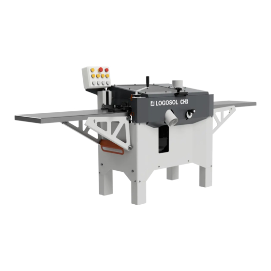
LOGOSOL CH3
EN
Advertisement
Table of Contents

Related Manuals for Logosol LOGOSOL CH3


Summary of Contents for Logosol LOGOSOL CH3
- Page 1 USER MANUAL ORIGINAL USER MANUAL. 0458-395-5502 LOGOSOL CH3 Read through the user manual carefully and make sure you understand its contents before using the equipment. This user manual contains important safety instructions. WARNING! Incorrect use can result in serious or fatal injuries to the...
- Page 2 LOGOSOL has been manufacturing wood processing equipment since 1989, and during these years we have supplied approximately 100,000 machines to satisfied customers the world over.
-
Page 3: Table Of Contents
LOGOSOL CH3 PLANER TABLE OF CONTENTS General information Description of the machine Components Safety instructions Chip collection Setting up Control panel Component parts (in-feed table) Assembly Side cutters Top cutter Planer adjustment Setup Maintenance instructions Planing Troubleshooting Technical data Wiring diagram... -
Page 4: General Information
GENERAL INFORMATION This user manual and instructions for accessories must be considered as part of the machine and always be stored with the machine. They must also accompany the machine if the machine is sold. The responsibility for ensuring that the machine is operated correctly and safely lies with the person who uses it. -
Page 5: Components
LOGOSOL CH3 PLANER COMPONENTS Bottom view: LOGOSOL CH3 Chassis Planer table Movable side cutter Feed motor Horizontal cutter Side cutter Table extension Front view: Junction box Control box 1005 2610 Top view: End: Rear:... -
Page 6: Safety Instructions
SAFETY INSTRUCTIONS KEY TO SYMBOLS WARNING! This symbol means that you Always wear approved ear protection have to take particular care. It is always when working with the machine. Even accompanied by information on the specific brief exposure to high frequency noise can risk. - Page 7 Use only LOGOSOL manufactured products or those expressly • Make sure that no one other than the operator approved by LOGOSOL for the purpose when is in the risk zone. adding extra equipment. • Check that the cutters can rotate freely and that no knives or unattached parts have been left in WARNING! Risk of ejection.
-
Page 8: Chip Collection
CHIP COLLECTION SETTING UP The Logosol CH3 must be connected to a chip Always have a complete first aid kid accessible extractor with a capacity of at least 2500 m3/h. at the workplace. Remember that you must have an air outlet in your chip container (e.g. -
Page 9: Control Panel
LOGOSOL CH3 PLANER CONTROL PANEL The control panel is not mounted upon delivery, but is packed in the machine on the planer table. The panel is to be mounted on the in-feed side of the planer. The component package, which is also on the planer table in the machine, contains the two screws for mounting the control panel. -
Page 10: Component Parts (In-Feed Table)
UPON DELIVERY The machine comes with a knife and shim kit, as well as an in-feed table with the following parts. 00-00081-div Box of tools CH3 NEU 7502-001-0701 Shims 30x42x0.1 Shims 30x42x0.1 7502-001-0702 7502-001-0703 Shims 30x42x0.3 7502-001-0705 Shims 30x42x0.5 7502-001-0710 Shims 30x42x1 7502-001-0720 Shims 30x42x2... - Page 11 LOGOSOL CH3 PLANER 02-00459 01-00614 04-00424 7 x – M6x20 03-02770 11 x – M6 12 x – M6 03-02769 2 x – M6x50 4 x – M12 03-03078 2 x – M12 03-02944 04-00425 SCREWS/BOLTS/NUTS/WASHERS Definition of fasteners. Guide pin...
- Page 12 UPON DELIVERY The CH3 is delivered partially adjusted. The two guides on the side of the fixed side cutter must be mounted and adjusted before setting up the planer. CONTROL BOX INSTALLATION The control box is to be installed on the back of the machine on the in-feed side.
-
Page 13: Assembly
LOGOSOL CH3 PLANER ASSEMBLY 4 x – M6x20 4 x – M6 8 x – M6 4 x – M12 NV18 2 x – M6x50 6 x – M6 3 x – M6x20 3 x – M6 6 x – M6... - Page 14 ADJUSTMENT Attachment side adjustment For optimal precision of the planed workpiece, the in-feed tables must be adjusted before use. Start by adjusting the height of the table so that it matches the lateral and vertical angles of the planer table. This is adjusted with the in-feed table mounting screws on the underside of the in-feed table.
-
Page 15: Side Cutters
LOGOSOL CH3 PLANER SIDE CUTTERS Knife replacement Loosen the locking screw (B) with a 4 mm Allen key and remove the chip breaker (D). Now remove the knife (E). Insert a new knife and securely tighten the locking screws. Make sure you turn the knives in the right direction when mounting them in the cutter. -
Page 16: Top Cutter
TOP CUTTER Before opening the safety hatch on the planer, make sure that the power is off and that the cutters are not rotating. Wear protective gloves, especially when loosening tight-fitting bolts/ screws or when tightening bolts/screws (see Safety precautions). Pay special attention to the planer knives. - Page 17 TOP CUTTER Adjust the knife knives so that they reach the same level and have a one millimetre protrusion. This is most easily done using Logosol's aluminium adjustment block. Slightly loosen the wedge locking screws, and slide the adjustment block over the knife. Adjust the knife up or down with the adjusting screws until the knife touches the block when it is moved over the knife.
- Page 18 TOP CUTTER Adjustment of top cutter removal The top cutter's degree of removal is set with the crank at the left corner of the planer. This crank raises or lowers the planer table in the machine via a chain transmission. Set the scale on the front of the machine, which shows the desired thickness of the workpiece.
-
Page 19: Planer Adjustment
LOGOSOL CH3 PLANER PLANER ADJUSTMENT IMPORTANT! To ensure good precision of the finished workpiece, it is important to adjust the guides before starting for the machine to produce satisfactory results. Carefully follow the adjustment sequence! GUIDE ADJUSTMENT, IN-FEED SIDE Start by adjusting the angle of the guide on the in-feed side, using a straight-edge placed against the guide. -
Page 20: Setup
FINISHED WORKPIECE Work is greatly facilitated if you have taken the time before starting to prepare a drawing of the finished workpiece that you intend to produce. This also facilitates communication with Logosol if you need to buy new moulding knives. - Page 21 LOGOSOL CH3 PLANER SETUP MOUNTING KNIVES IN SIDE CUTTERS Install the moulding knife that matches the setup drawing in the side cutters; see section on side cut- ters. ADJUST THE REMOVAL DEPTH ON THE FIXED SIDE CUTTER Set the removal depth on the movable guide on the in-feed side;...
- Page 22 SETUP MOUNT PLANING KNIVES AND ANY MOULDING KNIVES IN THE TOP CUTTER Mount planing knives and any moulding knives in the top cutter. Use the measured "0" to position the moulding knives in the top cutter. EXAMPLE: This example shows the placement of moulding knife to produce a radius on the fixed side cutter side.
- Page 23 LOGOSOL CH3 PLANER SETUP SIDE CUTTER SETUP Once you know the final measurements of the workpiece, it's time to set up the side cutters. When the drawing is to be used for setting up the planer, the planer table is regarded as "0" for the finished workpiece.
- Page 24 SETUP SET THE REMOVAL DEPTH ON THE MOVA- BLE SIDE CUTTER Carefully set the removal depth for the movable side cutter based on the side cutter's smallest outer diameter. A straight-edge here facilitates the rough adjustment of the removal depth. SETTING THE SIDE CUTTER'S REMOVAL DEPTH SCALE Movement of the side cutter is 4 mm per...
-
Page 25: Maintenance Instructions
LOGOSOL CH3 PLANER MAINTENANCE MAINTENANCE The periodic maintenance on the machine that is expected to be performed by the operator is described in this section. Be sure to follow the specified maintenance intervals, as this is the basis for good function of the planer. - Page 26 The table should be regularly cleaned and treated with same panel) it can rust. Set the cutter to its maxi- lubricant, e.g. low viscosity oil or wax. Logosol's lub- mum position and minimum position at some point ricant is especially made for woodworking machines.
-
Page 27: Planing
Normally only Edge angle shorter pieces are straightened for furniture joinery or Logosol's planer knives have a 38 degree angle on the window manufacturing, for example. knives and 20 degrees in the cutter. Some claim that a These two types of planers should not be confused. - Page 28 PLANING • Take care when setting the side guides. The rear obliquely; moreover, there will be deeper marks guide must be at the exact level of the cutter's caused by the roller grooves. Balancing the feed outer diameter. The two guides must be parallel rollers is especially important when planing nar- and set so that boards are fed slightly obliquely row workpieces.
-
Page 29: Troubleshooting
1. The planer knives are set to 1. Adjust planer knife removal with moulding knives. too low removal. Logosol's adjustment block or with 2. The moulding knives have magnetic adjustment for the top been incorrectly sharpened. cutter to 1 mm or, if necessary, a few tenths of a millimetre more. - Page 30 5. Clean the table and lubricate it 5. There is resin or rust on the with Logosol's planing lubricant planer table. 6. Check the gear locking screws 6. One or more of the gears in...
-
Page 31: Technical Data
LOGOSOL CH3 PLANER TECHNICAL DATA CUTTER 2/3 VERTICAL CUTTER DIMENSIONS/WEIGHT Spindle diameter 30 mm Length 1100 mm Max. cutter height* 40 mm Height 1150 mm Max. tool diameter 140 mm Width 720 mm Power 1.5 kW Weight 250 kg 300 RPM Max., moulding protrusion... -
Page 32: Machine Declaration
In accordance with Directive 2006/42/EC, Annex 2A Logosol AB, Fiskaregatan 2, S-871 33 Härnösand, Sweden Tel. +46 611 18285, hereby certifies that Planer Logosol CH3, with art. no. 7800-000-3000 has been manufactured in conformity with: Machinery Directive 2006/42 / EC, EMC Directive 2004/108 / EU...
Need help?
Do you have a question about the LOGOSOL CH3 and is the answer not in the manual?
Questions and answers