Table of Contents
Advertisement
SPECIFICATIONS
The Product with PbF
Pick-up Device:
Scanning Area:
Scanning:
Horizontal:
Vertical:
Synchronization:
Video Output:
Horizontal Resolution:
Signal-to-Noise Ratio:
Dynamic Range:
Minimum Illumination:
Gain Control:
White Balance:
Aperture:
Super Dynamic2:
Electronic Shutter Speed:
Lens
Focal length:
Maximum aperture ratio:
Angular field of view:
Focusing range:
Ambient Operating Temperature:
Ambient Operating Humidity:
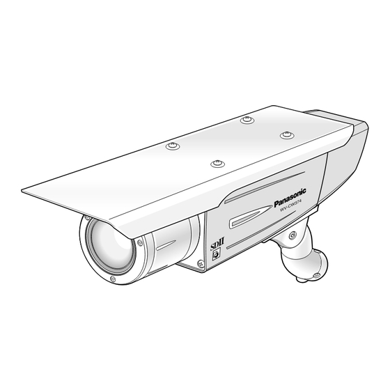
WV-CW370 / WV-CW374E
752 (H) x 582 (V) pixels, Interline Transfer CCD
4.8 (H) x 3.6 (V) mm (Equivalent to scanning area of 1/3" pick-up tube)
625 lines/50 fields/25 frames
15.625 kHz
50 Hz
Internal, Line-locked or Multiplexed vertical drive (VD2) Sync selectable
1.0 V[P-P] PAL composite 75 Ω/BNC connector
480 lines (C/L Normal), 510 line (C/L, HIGH), 570 lines (B/W)
50 dB (Equivalent to AGC Off, weight On, AP On)
48 dB (Typ)
1.0 lx (0.10 footcandle) (WIDE) (C/L),
0.15 lx (0.015 footcandle) (WIDE) (B/W)
ON (HIGH, MID, LOW)/OFF selectable
ATW1, ATW2 or AWC (SET UP MENU) selectable
Set Variable (SET UP MENU)
ON or OFF (SET UP MENU) selectable
OFF, 1/120, 1/250, 1/500, 1/1 000,1/2 000,
1/4 000, 1/10 000 s selectable
5 mm - 40 mm
1:1.6 (Wide), 1:1.9 (Tele)
Horizontal: 6.6 ° - 52 °
Vertical:
5.0 ° - 39.6 °
1.2 m - ∞ (3.9 ft - ∞)
–30 °C - +50 °C (–22 °F - 122 °F)
Less than 90 %
Colour CCTV Cameras
7 4
W 3
- C
W V
©
2 0 0 4
M a t s u s h i t a E l e c t r i c I n d u s t r i a l C o . , L t d .
A l l r i g h t s r e s e r v e d . U n a u t h o r i z e d c o p y i n g a n d
d i s t r i b u t i o n i s a v i o l a t i o n o f l a w .
ORDER NO. AVS0406573C8
Advertisement
Table of Contents

Related Manuals for Panasonic WV-CW370


Summary of Contents for Panasonic WV-CW370
-
Page 1: Specifications
ORDER NO. AVS0406573C8 Colour CCTV Cameras WV-CW370 / WV-CW374E SPECIFICATIONS The Product with PbF Pick-up Device: 752 (H) x 582 (V) pixels, Interline Transfer CCD Scanning Area: 4.8 (H) x 3.6 (V) mm (Equivalent to scanning area of 1/3” pick-up tube) -
Page 2: Standard Accessories
24 V AC 50 Hz, 3.7 W 12 V DC 365 mA For heater 24 V AC 50 Hz, 11W WV-CW370 220-240 V AC 50 Hz, 13 W Dimensions 78 mm (H) x 82 mm (W) x 301 mm (L) 3-1/16”... -
Page 3: Table Of Contents
[1]..............................4-2-2 [2]..............................4-2-3 [3]..............................4-2-4 [4]..............................4-2-5 SW BOARD .............................. 4-3 POWER 1 BOARD FOR WV-CW370....................... 4-4 POWER 1 BOARD FOR WV-CW374E ....................4-5 POWER 2 BOARD FOR WV-CW370......................4-6 POWER 2 BOARD FOR WV-CW374E .....................4-7 CONDUCTOR VIEW SENSOR BOARD............................. 5-1 MAIN BOARD............................ -
Page 4: Major Operating Controls And Their Functions
MAJOR OPERATING CONTROLS AND THEIR FUNCTIONS 1 SYNC 2 UPSIDE DOWN 3 AP GAIN SHARP SOFT 4 BW OFF AUTO 5 BW AUTO LOW HIGH LEVEL 6 LED q LEFT Button Moves the cursor to the left and selects items in the CAM SETUP menu. w UP Button Moves the cursor upward and selects items in the CAM SETUP menu. - Page 5 Connect to 24 V AC 50 Hz (19.5 V-28 V) class 2 power supply only. !4 Video output cable with BNC connector Connects with the video connector of the monitor. !5 Power cable (WV-CW370) Connect AC power cord to a 220-240 V AC 50 Hz Brown (Live)
-
Page 6: List Of Consumption Parts
LIST OF CONSUMPTION PARTS REF.NO. PART NAME LIFE IR Filter Mechanical Ass'y 10,000 ON/OFF actions 8 Those figures are just for a reference under 35 °C environmental temperature and not for a guarantee. It changes depending on the actual environment/operating condition. 8 Part numbers of these consumption parts are described in Replacement Parts List on page 7-1. -
Page 7: Adjustment Procedure
Mounting Bracket and remove the Mounting Bracket from The following Test Equipments are required for Adjust- the Camera Mount Adapter. ment of the Colour CCTV Camera WV-CW370 and 8 Remove four screws that secure the Camera Mount CW374E. Adapter and remove the Camera Mount Adapter from the 8 Oscilloscope Camera. - Page 8 Referring to Fig.2-4, remove one screw that secure the Referring to Fig. 2-5, remove four screws that secure the Rear Cover and remove the Rear Cover from the Camera. Rear Escutcheon and remove the Rear Escutcheon from the Camera. Disconnect the connector CN1 on the Power 1 Board and Remove one Screw.
- Page 9 3. Optical Ass'y Replacement 8 Referring to Fig. 2-7, remove two screws that secure the Front Unit and remove the Front Unit from the Main Unit Procedure of the Camera. 8 Disconnect the connector CN1 on the Main Board and 8 Remove the Front Unit from the Camera while referring to remove the Flexible Flat Cable.
- Page 10 Power Supply Unit Select switch #2 to ON (PAL) position. Test Chart (For WV-CW374E) 220-240 V AC (For WV-CW370) <SW3> Fig. 4-1 Connect the probe of the Oscilloscope or Frequency NTSC counter at the desired Test Point in each adjustment step.
- Page 11 8 Referring to Fig 5-1-2, loosen the Flange-back Lock 4.3. Setting Up Screw that secure the Flange-back Adjusting Lever. 8 Adjust the Flange-back Adjusting Lever to obtain best 8 An initial setting of the Switch on the WV-CW370 and focal point. WV-CW374E as follows: Sync Switch (1) (INT, LL) ..............INT...
- Page 12 Table 5-1. (2). High Clip Level Adjustment Test Point: Video Output Cable PANASONIC REMOTE EVR ADJUSTMENT SYSTEM CCTV PRODUCT:CW370 EEPROM:0 8 Confirm the Colour Temperature at 3 200°K. MENU Page (1/1) 8 Aim the Camera at the Logarithmic Gray Scale Chart.
- Page 13 (6.2). Burst Level Adjustment Test Point: Video Output Cable 8 Keep the Colour Temperature at 3 200°K. 8 Aim the Camera at the Logarithmic Gray Scale Chart. 8 Connect the terminated Oscilloscope with 75 Ω to the Video Output Cable. 700 mV ±...
- Page 14 (6.4). Burst Level Adjustment (7.1). White Balance 3 200°K Manual Offset R Adjustment Test Point: Video Output Cable 8 Keep the Colour Temperature at 3 200°K. Test Point: Video Output Cable 8 Aim the Camera at the Logarithmic Gray Scale Chart. 8 Keep the Colour Temperature at 3 200°K.
- Page 15 (9.2). 3 200°K B Gain Adjustment (8.1). White Balance 6 500°K ATW Limit R Adjustment Test Point: Video Output Cable 8 Keep the Colour Temperature at 3 200°K. Test Point: Video Output Cable 8 Adjust data with the ARROW keys so that the Yellow gain 8 Change the Colour Temperature from 3 200°K to 6 500°K becomes 120 % ±...
- Page 16 (10.2). 5 100°K B Gain Adjustment (12.1). Line Lock Phase Coarse Adjustment Test Point: Video Output Cable Test Point: Video Output Cable 8 Keep the Colour Temperature at 5 100°K. Live (Brown) of the Camera Power Cable 8 Adjust data with the ARROW keys so that the Yellow gain 8 Change the Colour Temperature from 3 200°K to 5 100°K becomes 120 % ±...
- Page 17 WIRING DIAGRAM FOR WV-CW370 SW BOARD VIDEO OUTPUT CABLE (VIDEO OUTPUT CABLE WITH BNC CONNECTOR) Live (Brown) POWER CABLE Neutral (Blue) GND (Green / Yellow) CN11 (MO1) POWER 2 BOARD POWER 1 BOARD OPTICAL ASS'Y (IC20) (SC VCXO) (Pattern Side)
-
Page 18: Wiring Diagram
WIRING DIAGRAM FOR WV-CW374E SW BOARD VIDEO OUTPUT CABLE (VIDEO OUTPUT CABLE WITH BNC CONNECTOR) FOR CAMERA Live (Brown) Neutral (Blue) POWER CABLE GND (Green / Yellow) Live (Black) Neutral (Gray) FOR HEATER CN11 (MO1) POWER 2 BOARD POWER 1 BOARD OPTICAL ASS'Y (IC20) - Page 19 SCHEMATIC DIAGRAM OF SENSOR BOARD SENSOR BOARD Note : • IC20 (Optical Ass'y) is not included in the Sensor Board Ass'y AGC5V -10V L309 OPEN 10.5V TD11 TD15 TD19 TD23 TD27 TD31 TD35 IC306 R154 TD13 TD17 TD21 TD25 TD29 TD33 TD37 VOUT...
- Page 20 PARTITION DIAGRAM FOR SCHEMATIC DIAGRAM OF MAIN BOARD MAIN BOARD (Refer to the page 4-2-2.) (Refer to the page 4-2-3.) (Refer to the page 4-2-4.) (Refer to the page 4-2-5.) • The Schematic Diagram of Main Board is described by 4 partitions. •...
- Page 21 SCHEMATIC DIAGRAM OF MAIN BOARD [1] <LOCATION MARK> MAIN BOARD TD220 TD222 TD219 TD221 OUT1 GND_2 BWEN BWEN OUT2 ENA1 ENA2 OUT1 OUT3 OUT3 OUT1 OUT3 OUT4 OUT2 OUT4 Attachment1 OUT2 OUT4 Attachment2 GND_1 VCONT IR FILTER MECHANICAL ASS'Y (M35) TD206 TD204 3.3V...
- Page 22 SCHEMATIC DIAGRAM OF MAIN BOARD [2] <LOCATION MARK> <INDEX> MAIN BOARD C2,C3, D2,D3 G3,H3 E4,E5,E6, F4,F5,F6 IC14 TD200 B4,B5, C103 C4,C5 COMMON R151 5.6k ch_0 1000p B6,B7, C100 2200p ch_1 3.3V IC15 C6,C7 C102 0.047 C101 R150 IC19 A_OUTPUT R152 OPEN R149 IC10...
- Page 23 SCHEMATIC DIAGRAM OF MAIN BOARD [3] TGV3 TCH1 TCH1 TGV2 TD218 TGV2 TSUB TSUB TGV1 IC18 TGV1 3.3V MA3.3V FCK2 FCK2 TDS2 TDS1 OPEN C112 CPOB CPOB HCLR2 HCLR2 ADO[9] SDOUT SDOUT SDIN SDIN DACLD SCLK SCLK ROMCS VSSA n.c._6 3.3TV 3.3V DSP3.3V...
- Page 24 SCHEMATIC DIAGRAM OF MAIN BOARD [4] DSP1.8V DSP3.3V TD12 TD15 TD19 TD21 TD10 TD13 TD17 TD20 IC11 DSP3.3V IN_B DSP1.8V IN_A R177 OUT_Y R116 FLKA INT/LL INT/LL 300k BWSW BWSW UPSIDEDOWN UPSIDEDOWN REFO S-GLIN GL/FLK/LED OFF SIGN465 LLDET/LPFI LP/LPFO 485EN BEND VSS334 ACTS...
- Page 25 SCHEMATIC DIAGRAM OF SW BOARD SW BOARD 3.3V 3.3V 3.3V 1-7 : SYNC SWITCH (1) SHARP SOFT 2-8 : UPSIDE DOWN AUTO SWITCH (2) HIGH 3-9 : AP GAIN SWITCH (3) 4-10 : BW SWITCH (4) 5-11 : BW AUTO LEVEL SWITCH (5) 6-12 : LED ON/OFF SWITCH (6)
- Page 26 SCHEMATIC DIAGRAM OF POWER 1 BOARD FOR WV-CW370 POWER 1 BOARD AC (L) AC (N) 250V POWER CABLE (E11) LP/LPFO LLDET/LPTI 10.5V 1/4W EXT BW/LED GND[24V] POWER 2 BOARD AGN D 1500p DGND Important safety notice Components identified by "...
- Page 27 SCHEMATIC DIAGRAM OF POWER 1 BOARD FOR WV-CW374E POWER 1 BOARD 3.15A 250V FOR HEATER AGND 24V AC (L) 24V AC (N) 24V AC (L) 3.15A – 24V AC (N) 250V (12V DC) (24V AC) FOR CAMERA POWER CABLE (E11) 0.22 1/4W LP/LPFO...
- Page 28 SCHEMATIC DIAGRAM OF POWER 2 BOARD FOR WV-CW370 POWER 2 BOARD <INDEX> POWER 2 BOARD 330 1W C3,C4 C3,C4 FAN- (VS4) FAN+ C3,C4 Attachment1 (MO1) Attachment2 B1,B2 C2,D2 TP14 TP12 24.1V TP13 TP11 TP10 C2,B2 OPEN 3.0V B1,B2 10.5V 1.8V 3.31V...
- Page 29 SCHEMATIC DIAGRAM OF POWER 2 BOARD FOR WV-CW374E POWER 2 BOARD <INDEX> POWER 2 BOARD 330 1W C3,C4 C3,C4 FAN- (VS4) C3,C4 FAN+ Attachment1 (MO1) Attachment2 B1,B2 C2,D2 TP14 TP12 24.1V TP13 TP11 TP10 C2,B2 OPEN 3.0V 10.5V 1.8V 3.31V 3.30V 1 Cont 2 GND_1...
- Page 30 EXPLODED VIEW (1/5) Numbers show screws and washers. Camera Unit Screws Description XSB3+8V Binding Head Machine Screw Serial No. Label XSB3+6V Binding Head Machine Screw XYM26+A6V Binding Head Machine Screw and Washer Ass'y XYM3+J10V Binding Head Machine Screw and Washer Ass'y Main Unit (Refer to the page 6-2.)
-
Page 31: For Wv-Cw370
Binding Head Machine Screw and Washer Ass'y XSB26+8V Binding Head Machine Screw XSB2+4V Binding Head Machine Screw Power Unit (Refer to the page 6-4 for WV-CW370.) (Refer to the page 6-5 for WV-CW374E.) Front Unit (Refer to the page 6-3.) Rear Unit (Refer to the page 6-4 for WV-CW370.) - Page 32 EXPLODED VIEW (3/5) Numbers show screws and washers. Screws Description XSB2+5FN Binding Head Machine Screw XYM2+J6FN Binding Head Machine Screw and Washer Ass'y Front Unit IC20 PCB1 PCB2...
- Page 33 EXPLODED VIEW (4/5) FOR WV-CW370 Numbers show screws and washers. Screws Description XSB2+5FN Binding Head Machine Screw Rear Unit for WV-CW370 XYM2+J6FN Binding Head Machine Screw and Washer Ass'y XSN26+14FN Pan Head Machine Screw XTB2+6GFX Binding Head Tapping Screw XSB4+6FX...
- Page 34 EXPLODED VIEW (4/5) FOR WV-CW374E Numbers show screws and washers. Screws Description XSB2+5FN Binding Head Machine Screw Rear Unit for WV-CW374E XYM2+J6FN Binding Head Machine Screw and Washer Ass'y XSN26+14FN Pan Head Machine Screw XTB2+6GFX Binding Head Tapping Screw XSB3+8V Binding Head Machine Screw XSB3+6V Binding Head Machine Screw...
- Page 35 EXPLODED VIEW (5/5) PACKAGING WV-CW370 WV-CW374E Bar Code Label...
-
Page 36: Important Notice
Main Board CN1 3DA001914AAA Insulation Case for WV-CW370 VCW37J01 Lens Relay Cable for Sensor Board CN300 and Lens Ass’y YWA7SA0689A4 Earth Mark Label for WV-CW370 K9ZZ00000943 Flexible Flat Cable for Main Board CN4 and 3CG001046BAA Rear Escutcheon Power 2 Board CN2 1CL001063AAA... -
Page 37: Sensor Board
REF. NO. PART NO. DESCRIPTION REF. NO. PART NO. DESCRIPTION F1H1H103A219 Ceramic 0.01 µF SENSOR BOARD F1H0J105A001 Ceramic 1 µF MCUV1E104ZFV Ceramic 0.1 µF Note: F1H0J105A001 Ceramic 1 µF 8 IC20 (Optical Ass'y) is not supplied as Printed Circuit Board Ass'y (PCB1). MCUV1E104ZFV Ceramic 0.1 µF... -
Page 38: Main Board
REF. NO. PART NO. DESCRIPTION REF. NO. PART NO. DESCRIPTION ERJ2GEJ514X Metal 510K ohms 1/16W MAIN BOARD ERJ2GEJ102X Metal 1K ohms 1/16W ERJ2GEJ201X Metal 200 ohms 1/16W PCB2 (RTL) VW374EKC1A Printed Circuit Board Ass’y ERJ2GE0R00X Metal 0 ohm 1/16W C0FBAF000048 A/D Converter ERJ2GEJ752 Metal... -
Page 39: Sw Board
REF. NO. PART NO. DESCRIPTION REF. NO. PART NO. DESCRIPTION R177 ERJ2GEJ102X Metal 1K ohms 1/16W C103 YW36B102K5T Ceramic 1000 pF R179 ERJ3GEY0R00V Metal 0 ohm 1/16W C104 F1G1H561A401 Ceramic 560 pF R181,183 ERJ2GE0R00X Metal 0 ohm 1/16W C106 F1G1C1040004 Ceramic 0.1 µF R184-186... -
Page 40: Power 1 Board For Wv-Cw370
REF. NO. PART NO. DESCRIPTION REF. NO. PART NO. DESCRIPTION F1J1H472A400 Ceramic 4700 pF POWER 1 BOARD for WV-CW370 F1B2E1520002 Ceramic 1500 pF EEUFC1C271 Electrolytic 270 µF 16V PCB4 (RTL) VCW370KB4A Printed Circuit Board Ass’y EEUFC1V221 Electrolytic 220 µF 35V... -
Page 41: Power 2 Board For Wv-Cw370
Electrolytic 100 µF 10V EEVHB1V101P Electrolytic 100 µF 35V MCUV1H474ZFM Ceramic 0.47 µF EEEFK1V220R Electrolytic 22 µF 35V POWER 2 BOARD for WV-CW370 C17-19 ECST1CY475R Tantalum 4.7 µF 16V C20-22 F1H1E104A030 Ceramic 0.1 µF PCB5 (RTL) VCW370KC4A Printed Circuit Board Ass’y... -
Page 42: Power 2 Board For Wv-Cw374E
Polyethylene Bag ECST1AY106R Tantalum 10 µF 10V YWT10X10C03 Polyethylene Bag PE20X35C05B Polyethylene Bag F1J1C105A004 Ceramic 1 µF V9CA4998AN Packaging Ass’y for WV-CW370 EEVHB1A101P Electrolytic 100 µF 10V V9CA4999AN Packaging Ass’y for WV-CW374E EEVHB1V101P Electrolytic 100 µF 35V MCUV1H474ZFM Ceramic 0.47 µF...
Need help?
Do you have a question about the WV-CW370 and is the answer not in the manual?
Questions and answers