Advertisement
Quick Links
Advertisement

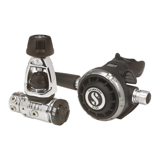
Summary of Contents for Johnson Outdoors SCUBAPRO G260
- Page 1 MAINTENANCE PROCEDURE G260 revision 02 2013-04...
- Page 2 2 - 11 MAINTENANCE PROCEDURE G260 – REVISION 02 - 2013-04...
- Page 3 3 - 11 MAINTENANCE PROCEDURE FOR G260 This maintenance procedure is based upon the attached schematic. WARNING This maintenance procedure is only for appointed Scubapro technicians that fol- lowed a complete course on equipment repair and in no case can replace a tech- nical repair course delivered by a SCUBAPRO/ UWATEC appointed staff.
- Page 4 4 - 11 Remove the purge button and spring by pushing on two of the four tabs of the purge button. Remove the o-ring from the thread of the inlet tube with the o-ring extractor and un- screw the nut with the universal tool Push slowly the inlet tube through the case by about 2 centimetres and rotate clock- wise about 45°.
-
Page 5: Parts Cleaning
5 - 11 21. It is not necessary to carry out this step unless the (V.I.V.A) flow vane needs re- placement. • Place the flow vane horizontally, then insert the flow vane extractor through the mouthpiece tube and place the slit of the tool on the flow vane. Position the rounded tip of the tool against the shoulder of the flow vane (the angled portion of the tool should rest on the mouthpiece tube) and use the tool as a lever to push the flow vane out of the housing. - Page 6 6 - 11 ASSEMBLY After careful inspection of the cleaned parts and the static o-rings that do not need re- placement, prepare all the parts that need to be changed at every annual service. O-ring (2x) 01.050.132 O-ring 01.050.347 O-ring (2x) 01.050.363 01.075.132 Seat...
- Page 7 7 - 11 In case the lever has been removed from the inlet tube, reassemble as follows: • First of all verify the symmetry of the lever when placed on a flat surface. The four legs should touch the flat surface without any distortion. In case of doubt, replace the lever.
- Page 8 8 - 11 15. Place the o-ring on the fine adjustment screw. Slightly lubricate the o-ring and threads and screw the fine adjustment screw with the 4 mm Allen key inside the adjustment knob, until the shaft comes about 2 mm. out on the other side.
- Page 9 9 - 11 ADJUSTMENT WARNING: To adjust a 2 stage correctly, it’s must be connected to a appropriate and well adjusted 1 stage (with a interstage pressure between 9,3 - 9,7 bar) and a tank with a minimal filling pressure of 200 bar. Check that the adjustment knob is still screwed out completely to achieve the lightest breathing resistance.
- Page 10 10 - 11 If the cracking effort is lower then indicated, use the 4 mm Allen key and screw by a ¼ turn the fine adjustment screw inside the adjustment knob. note : The adjustable orifice MUST always be readjusted as per paragraph 5 and 6 before measuring the cracking effort again.
- Page 11 11 - 11 MAINTENANCE PROCEDURE G260 – REVISION 02 - 2013-04...


Need help?
Do you have a question about the SCUBAPRO G260 and is the answer not in the manual?
Questions and answers