Download Print this page
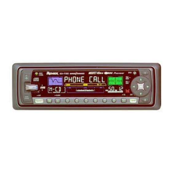
Pioneer DEH-P700R Service Manual

Pioneer DEH-P700R Service Manual

Multi-cd control high power cd player with rds or fm/am tuner

Advertisement

Quick Links

Service
Manual
MULTI-CD CONTROL HIGH POWER CD PLAYER WITH RDS TUNER
DEH-P700R
DEH-P7000R
MULTI-CD CONTROL HIGH POWER CD PLAYER WITH FM/AM TUNER
DEH-P7050
- See the separate manual CX-916(CRT2300) for the CD mechanism description, disassembly and circuit
description.
- The CD mechanism employed in this model is one of S8 series.
- This device employs an inverter as the power supply for EL. The inverter has an output voltage reach
approximately 500 volts(AC). Utmost care should be used not to suffer from a possible electric shock,
accordingly.
- When executing an operation, be aware that the in around IC651 can become quite hot to the touch.
CONTENTS
1. SAFETY INFORMATION ............................................2
2. EXPLODED VIEWS AND PARTS LIST .......................2
3. BLOCK DIAGRAM AND SCHEMATIC DIAGRAM ...14
4. PCB CONNECTION DIAGRAM ................................46
5. ELECTRICAL PARTS LIST ........................................56
6. ADJUSTMENT..........................................................70
PIONEER ELECTRONIC CORPORATION
PIONEER ELECTRONICS SERVICE INC.
PIONEER ELECTRONIC [EUROPE] N.V.
PIONEER ELECTRONICS ASIACENTRE PTE.LTD. 253 Alexandra Road, #04-01, Singapore 159936
C PIONEER ELECTRONIC CORPORATION 1999
DEH-P700R/UC
4-1, Meguro 1-Chome, Meguro-ku, Tokyo 153-8654, Japan
P.O.Box 1760, Long Beach, CA 90801-1760 U.S.A.
Haven 1087 Keetberglaan 1, 9120 Melsele, Belgium
UC
ES
7. GENERAL INFORMATION .......................................74
7.1 PARTS .................................................................74
7.1.1 IC................................................................74
7.1.2 DISPLAY ....................................................84
7.2 DIAGNOSIS ........................................................86
7.2.1 DISASSEMBLY .........................................86
7.2.2 TEST MODE ..............................................90
8. OPERATIONS AND SPECIFICATIONS.....................94
K-ZZD. FEB. 1999 Printed in Japan
ORDER NO.
CRT2373
UC

Advertisement

loading

Summary of Contents for Pioneer DEH-P700R

  • Page 1 PIONEER ELECTRONICS SERVICE INC. P.O.Box 1760, Long Beach, CA 90801-1760 U.S.A. PIONEER ELECTRONIC [EUROPE] N.V. Haven 1087 Keetberglaan 1, 9120 Melsele, Belgium PIONEER ELECTRONICS ASIACENTRE PTE.LTD. 253 Alexandra Road, #04-01, Singapore 159936 C PIONEER ELECTRONIC CORPORATION 1999 K-ZZD. FEB. 1999 Printed in Japan...
  • Page 2: Safety Information

    This product contains lead in solder and certain electrical parts contain chemicals which are known to the state of California to cause cancer, birth defects or other reproductive harm. Health & Safety Code Section 25249.6 - Proposition 65 2. EXPLODED VIEWS AND PARTS LIST 2.1 PACKING(DEH-P700R/UC)
  • Page 3 DEH-P700R,P7000R,P7050 NOTE: - Parts marked by “*” are generally unavailable because they are not in our Master Spare Parts List. ∇ mark on the product are used for disassembly. - Screws adjacent to - PACKING SECTION PARTS LIST Mark No. Description Part No.
  • Page 4 DEH-P700R,P7000R,P7050 2.2 PACKING(DEH-P7000R/UC) - PACKING SECTION PARTS LIST Mark No. Description Part No. Mark No. Description Part No. 1 Cord Assy CDE5827 16 Protector CHP2101 2 Accessory Assy CEA2395 17 Protector CHP2102 3 Spring CBH1650 18 Remote Control Unit CXB3455...
  • Page 5 DEH-P700R,P7000R,P7050 2.3 PACKING(DEH-P7050/ES) - PACKING SECTION PARTS LIST Mark No. Description Part No. Mark No. Description Part No. 1 Cord Assy CDE5828 (English, Spanish, Portuguese) 2 Accessory Assy CEA2395 20-2 Owner’s Manual CRD2904 3 Spring CBH1650 (Arabic, Chinese) 4 Screw Assy...
  • Page 6 DEH-P700R,P7000R,P7050 2.4 EXTERIOR(DEH-P700R/UC)
  • Page 7 DEH-P700R,P7000R,P7050 - EXTERIOR SECTION PARTS LIST Mark No. Description Part No. Mark No. Description Part No. 1 Screw BMZ30P040FMC 56 Screw CBA1176 2 Screw BSZ26P060FMC 57 Washer CBF1001 3 Screw BSZ30P060FMC 58 Spring CBH2063 4 Screw BSZ30P100FMC 59 Spring CBH2204...
  • Page 8 DEH-P700R,P7000R,P7050 2.5 EXTERIOR(DEH-P7000R/UC)
  • Page 9 DEH-P700R,P7000R,P7050 - EXTERIOR SECTION PARTS LIST Mark No. Description Part No. Mark No. Description Part No. 1 Screw BMZ30P040FMC 56 Screw CBA1176 2 Screw BSZ26P060FMC 57 Washer CBF1001 3 Screw BSZ30P060FMC 58 Spring CBH2063 4 Screw BSZ30P100FMC 59 Spring CBH2204...
  • Page 10 DEH-P700R,P7000R,P7050 2.6 EXTERIOR(DEH-P7050/ES)
  • Page 11 DEH-P700R,P7000R,P7050 - EXTERIOR SECTION PARTS LIST Mark No. Description Part No. Mark No. Description Part No. 1 Screw BMZ30P040FMC 56 Screw CBA1176 2 Screw BSZ26P060FMC 57 Washer CBF1001 3 Screw BSZ30P060FMC 58 Spring CBH2063 4 Screw BSZ30P100FMC 59 Spring CBH2204...
  • Page 12: Cd Mechanism Module

    DEH-P700R,P7000R,P7050 2.7 CD MECHANISM MODULE...
  • Page 13 DEH-P700R,P7000R,P7050 - CD MECHANISM MODULE SECTION PARTS LIST Mark No. Description Part No. Mark No. Description Part No. 1 Compound Unit CWX2235 46 Sheet CNM6215 2 Connector(CN802) CKS2192 47 Ball CNR1189 3 Connector(CN801) CKS2193 48 Belt CNT1086 4 Connector(CN701) CKS2773...
  • Page 14: Block Diagram And Schematic Diagram

    DEH-P700R,P7000R,P7050 3. BLOCK DIAGRAM AND SCHEMATIC DIAGRAM 3.1 BLOCK DIAGRAM(DEH-P700R/UC) TUNER AMP UNIT FM/AM TUNER UNIT COMPOUND UNIT PICKUP UNIT(SERVICE) PHOTO UNIT...
  • Page 15 DEH-P700R,P7000R,P7050 KEYBOARD UNIT...
  • Page 16 DEH-P700R,P7000R,P7050 3.2 BLOCK DIAGRAM(DEH-P7050/ES) TUNER AMP UNIT FM/AM TUNER UNIT PICKUP UNIT(SERVICE) COMPOUND UNIT PHOTO UNIT...
  • Page 17 DEH-P700R,P7000R,P7050 KEYBOARD UNIT...
  • Page 18 DEH-P700R,P7000R,P7050 3.3 OVERALL CONNECTION DIAGRAM(GUIDE PAGE)(DEH-P700R/UC) Note: When ordering service parts, be sure to refer to “EXPLODED VIEWS AND PARTS LIST” or “ELECTRICAL PARTS LIST”. Large size SCH diagram TUNER AMP UNIT Guide page Detailed page ANTENNA CABLE...
  • Page 19 DEH-P700R,P7000R,P7050 CEK1136 CLOSE S651 CSN1027 KEYBOARD UNIT...
  • Page 20 DEH-P700R,P7000R,P7050...
  • Page 21 DEH-P700R,P7000R,P7050...
  • Page 22 DEH-P700R,P7000R,P7050...
  • Page 23 DEH-P700R,P7000R,P7050...
  • Page 24 DEH-P700R,P7000R,P7050 3.4 OVERALL CONNECTION DIAGRAM(GUIDE PAGE)(DEH-P7000R/UC) TUNER AMP UNIT ANTENNA CABLE...
  • Page 25 DEH-P700R,P7000R,P7050 CEK1136 CLOSE S651 CSN1027 KEYBOARD UNIT...
  • Page 26 DEH-P700R,P7000R,P7050...
  • Page 27 DEH-P700R,P7000R,P7050...
  • Page 28 DEH-P700R,P7000R,P7050...
  • Page 29 DEH-P700R,P7000R,P7050...
  • Page 30 DEH-P700R,P7000R,P7050 3.5 OVERALL CONNECTION DIAGRAM(GUIDE PAGE)(DEH-P7050/ES) TUNER AMP UNIT ANTENNA CABLE...
  • Page 31 DEH-P700R,P7000R,P7050 CEK1136 CLOSE S651 CSN1027 KEYBOARD UNIT...
  • Page 32 DEH-P700R,P7000R,P7050...
  • Page 33 DEH-P700R,P7000R,P7050...
  • Page 34 DEH-P700R,P7000R,P7050...
  • Page 35 DEH-P700R,P7000R,P7050...
  • Page 36 DEH-P700R,P7000R,P7050 3.6 FM/AM TUNER UNIT Voltage of IC Terminals Mark Band Input Level None – – 0dBf 65dBf F125 125dBf 0dBµ 74dBµ A125 125dBµ...
  • Page 37 DEH-P700R,P7000R,P7050...
  • Page 38 DEH-P700R,P7000R,P7050 3.7 KEYBOARD UNIT KEYBOARD UNIT CAW1519 DEH-P700R/UC DEH-P7000R/UC CAW1518 DEH-P7050/ES...
  • Page 39 DEH-P700R,P7000R,P7050 GREEN GREEN...
  • Page 40 DEH-P700R,P7000R,P7050 3.8 CD MECHANISM MODULE COMPOUND UNIT PICKUP UNIT(SERVICE) PHOTO UNIT 10/6R3...
  • Page 41 DEH-P700R,P7000R,P7050 SWITCHES: COMPOUND UNIT S801 : HOME SWITCH..ON-OFF S802 : CLAMP SWITCH..ON-OFF The underlined indicates the switch position.
  • Page 42 DEH-P700R,P7000R,P7050 PML004AF PA2028A...
  • Page 43 DEH-P700R,P7000R,P7050 PML006A VCCO PGND GATE ISET-N ISET-D CLKC CLKR VDCSEN PM4009A...
  • Page 44 DEH-P700R,P7000R,P7050 PAL005A Protector Mute Mute Mute Mute Amp2 Amp3 Amp1 Amp4 STBY - Pin Functions (PD6279A) Pin No. Pin Name Function and Operation 1–42 SEG41–0 LCD segment output 43–46 COM3–0 LCD common output 47–49 V1–V3 LCD bias power supply Power supply terminal...

This manual is also suitable for:

Deh-p7000rDeh-p7050