
Related Manuals for Opvimus LS-320


Summary of Contents for Opvimus LS-320
- Page 1 SUPRESOR EFECTO LARSEN FEEDBACK SUPPRESSOR LS-320 Manual de instalación y funcionamiento v4.0 Installation and operating instructions v4.0...
- Page 2 Solamente el personal técnico cualificado debe instalar y operar este equipo. El usuario no deberá intentar usar el equipo para otras funciones que las descritas en este manual. LS-320 Versión 4.0 Página 1 de 12...
-
Page 3: Table Of Contents
4.2.2. Selección del modo de funcionamiento del filtro ............8 4.2.3. Edición de los parámetros del filtro ................9 4.2.4. Menú Auxiliar ......................9 4.2.5. Guardar programas ....................9 5. APÉNDICE ………………………………….………………………………………………. 10 5.1. Conexiones ....................... 10 5.2. Especificaciones ....................11 LS-320 Versión 4.0 Página 2 de 12... -
Page 4: Especificaciones
Indicador de 2 x 8 LEDs para monitorización de niveles de entrada o salida. Fuente de alimentación interna. El uso de componentes de alta calidad y el montaje automatizado aseguran la calidad y duración del equipo. LS-320 Versión 4.0 Página 3 de 12... -
Page 5: Descripción
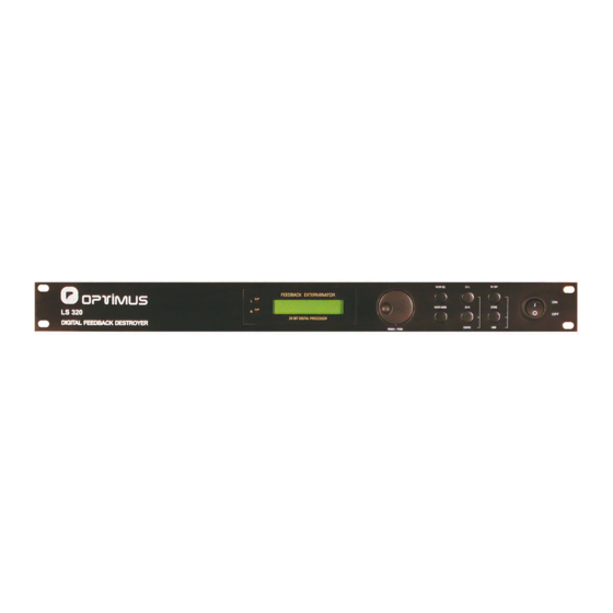
3. PANEL DE CONTROL Fig 1. Panel frontal LS-320 El LS-320 está equipado con seis teclas de funciones, un control rotativo de selección y un panel indicador de operación. Pueden utilizarse para modificar los parámetros o programas seleccionados visualizados en la pantalla LCD. -
Page 6: Menú De Control
(8) “SET”: Cuando “:” pase a “→” presione el control rotativo para entrar en el menú de ajuste del modo SING, donde podrá seleccionar el número de filtros en modo SING a utilizar. LS-320 Versión 4.0 Página 5 de 12... -
Page 7: Teclas De Funciones Y Control Rotativo
CHL y manteniendo ésta pulsada presiona CHR, los parámetros del canal izquierdo se copiarán al canal derecho. (6) BYPASS: Permite desactivar todos los filtros. (7) STORE: Presione tres veces para guardar. “SV” pasará a SC y desaparecerá indicando que los cambios han sido guardados. LS-320 Versión 4.0 Página 6 de 12... -
Page 8: Combinaciones De Teclas
(4) Conector de alimentación, fusible y selector de tensión. Antes de conectar la unidad asegúrese de que el indicador de tensión indique el mismo voltaje que el utilizado en la red. (5) Puerto RS-232: Permite conectar un PC para actualizar el equipo. LS-320 Versión 4.0 Página 7 de 12... -
Page 9: Funcionamiento
“→” sobre la opción de selección de programa. 4.2.2. Selección del modo de funcionamiento del filtro Identificación de modo de operación en pantalla. PANTALLA MODO DE OPERACION AUTO Auto SING Single-Shot LS-320 Versión 4.0 Página 8 de 12... -
Page 10: Edición De Los Parámetros Del Filtro
LED DISPLAY, puede seleccionarse la monitorización del nivel de entrada o de salida. SENSITIVE configurable en 5 grados, el primer grado es la máxima sensibilidad y el quinto la mínima. LS-320 Versión 4.0 Página 9 de 12... -
Page 11: Guardar Programas
Para mantener inalterados los parámetros iniciales del programa, use el control rotativo y seleccione un programa distinto antes de pulsar STORE por tercera vez. Las modificaciones sobre el programa “0” no pueden guardarse. LS-320 Versión 4.0 Página 10 de 12... -
Page 12: Apéndice
Supresor efecto Larsen 5. APÉNDICE 5.1. Conexiones Para pasar de conexión balanceada a no balanceada, en el jack deben puntearse el anillo y el vástago, y en el XLR unirse los pines 1 y 3. LS-320 Versión 4.0 Página 11 de 12... -
Page 13: Especificaciones
220 ~ 240 Vca, 50 ~ 60 Hz Fusible 220 ~ 240 Vca: 125 mA Consumo 10 W 45 (alto) x 482 (ancho) x 152 (fondo) Dimensiones (mm) Peso 3 kg Acabado Frontal y tapa en skinplate Color Negro LS-320 Versión 4.0 Página 12 de 12... - Page 14 Only qualified service personnel should be allowed to install and operate the unit. The user should not attept to use the unit beyond the description listed in the user’s manual. LS-320 Version 4.0 Page 1 of 12...
- Page 15 Recalling programs ....................8 4.2.2 Choice of mode ......................8 4.2.3 Editing filter parameters ..................... 9 4.2.4 Auxiliary menu ......................9 4.2.5 Storing programs ...................... 10 APPENDIX ......................... 11 Connections ......................11 Specifications ...................... 12 LS-320 Version 4.0 Page 2 of 12...
-
Page 16: Specifications
Back-lit 2 x 16 digital numeric LCD display. 2 x 8 LED LEVEL indicator, displaying the input or output level. Internal power supply. High quality components with automatic assembly ensure quality and durability. LS-320 Version 4.0 Page 3 of 12... -
Page 17: Description
3. CONTROL PANEL Fig 1. Front Panel of the LS-320 LS-320 is equipped with six function keys, and a jog wheel. They can be used to modify the selected parameter or preset shown in the LCD display. LS-320 Version 4.0... -
Page 18: Control Menu
STORE once more, “SC” will disappear, it means that settings have been memorized. “SET”: when “:” change to “→ “ press PUSH to enter into setting menu of SING mode filter in SING order to select the mode filters number. LS-320 Version 4.0 Page 5 of 12... -
Page 19: Function Keys And Jog Wheel
(4) CHL (Left channel): Edits left channel parameters. (5) CHR (Right channel): Edits left channel parameters. If you want to edit both channels, press simultaneously CHL and CHR keys. Last individual channel’s settings will then be the same for both. LS-320 Version 4.0 Page 6 of 12... -
Page 20: Combination Keys
(4) MAINS CONNECTOR / FUSE HOLDER / VOLTAGE SELECTOR: Before you connect the unit, please make sure that the displayed voltage corresponds to your Mains supply. (5) RS-232 port: You can link the unit to a PC via RS-232 port for firmware updates. LS-320 Version 4.0 Page 7 of 12... -
Page 21: Operation
After start-up, the display reads the number of the preset last used. The jog wheel allows you to conveniently select the preset of your choice. 4.2.2 Choice of mode Each filter mode’s display messages can be recognized. DISPLAY OPERATION MODE AUTO Auto SING Single-Shot LS-320 Version 4.0 Page 8 of 12... -
Page 22: Editing Filter Parameters
Q can be set to 1/10 or 1/5, which is effective when finds a new suppress point. LED DISPLAY current channel input level or output level. SENSITIVE has 5 grades. The first grade is the highest sensitivity; the fifth one is the lowest. LS-320 Version 4.0 Page 9 of 12... -
Page 23: Storing Programs
However, if you wish to keep the original preset, use the jog wheel to select another preset before you press the STORE key a second time. Modifications of default program (0) can not be stored. LS-320 Version 4.0 Page 10 of 12... -
Page 24: Appendix
Feed Back Suppressor 5. APPENDIX 5.1 Connections To unbalance a balanced connection, you can connect the ring with tip on jack connector and pins 1 and 3 on XLR connector. LS-320 Version 4.0 Page 11 of 12... -
Page 25: Specifications
220 ~ 240 Vac, 50 ~ 60 Hz Fuse 220 ~ 240 Vac: 125 mA Power consumption 10 W Dimensions (mm) 44 (high) x 482 (width) x 152 (depth) 3 kg Weight Finishing Skin plate Colour Black LS-320 Version 4.0 Page 12 of 12...
Need help?
Do you have a question about the LS-320 and is the answer not in the manual?
Questions and answers