Table of Contents
Advertisement
Quick Links
Advertisement
Table of Contents

Related Manuals for Grant VortexAir


Summary of Contents for Grant VortexAir
- Page 1 Grant VortexAir VortexBlue Oil Boiler and Aerona³ Air Source Heat Pump Hybrid Installation and Servicing Instructions THESE INSTRUCTIONS SHOULD BE READ IN CONJUNCTION WITH THE INSTALLATION AND SERVICING INSTRUCTIONS SUPPLIED WITH THE HEAT PUMP . UK | DOC 0110 | Rev 1.0 | November 2016...
- Page 2 However, no responsibility of any kind for any injury, death, loss, damage or delay however caused resulting from the use of this manual can be accepted by Grant Engineering (UK) Limited, the author or others involved in its publication.
-
Page 3: Table Of Contents
Contents Introduction 11 Domestic Hot Water General 11.1 Temperature Control Outputs 11.2 Legionella Planning Permission 11.3 Grant Automatic DHW Boost Kit 2 DNO Application 11.4 Grant Digital 2-Stage Cylinder Thermostat Servicing Important Advice 12 Electrical Product Contents 12.1 General Installation Accessories 12.2 Hybrid (Boiler) Electrical Supply... -
Page 4: Introduction
Aerona³ heat pump is used in both models. Heat Pump: 16kW* The Grant VortexAir is supplied in two parts, the oil boiler and the Boiler: 21/26kW (factory setting 26kW) heat pump (each on their own pallets), for connection together by... -
Page 5: Important Advice
Heat meter HPIDHEATMETER situation to occur. Please seek advice from Grant UK if any of (Refer to Section 7-2) these user, installation and servicing instructions cannot be Electricity meter HPIDKW/HMETER followed for whatever reason. -
Page 6: Hybrid Components
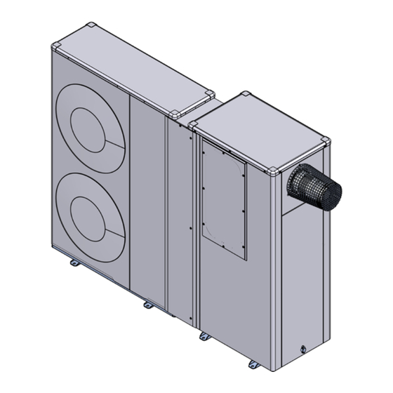
1.9 Hybrid Components Figure 1-5: Main components - front Figure 1-6: Main components - rear (oil boiler casing removed) Page 6 Section 1: Introduction... - Page 7 Figure 1-7: Knockouts for oil lines and condensate disposal Table 1-8: Key to main components - front Item Front (removable) access To access the heat pump wiring centre cover Flue (external applications) Refer to Section 13 Control panel Refer to Section 10 Blue flame burner A Riello high-efficiency, low NOx blue flame burner with plug and socket connection Pump...
-
Page 8: Technical Data
2 Technical Data 2.1 Boiler Technical Data Table 2-1: Boiler technical data Unit HPIDAIR - 15/21kW HPIDAIR2 - 21/26kW litre 16.5 / 2.0 (18.5) 10.5 / 2.0 (12.5) Water content - oil boiler / heat pump (total) gallon 3.6 / 0.44 (4.04) 2.3 / 0.44 (2.74) Weight - oil boiler and heat pump (empty)* 290.2... -
Page 9: Sealed System Data
15 mm copper pipe Pressure relief valve discharge connection * 15 mm copper pipe * Provided that a Grant UK sealed system kit (listed in Table 1-4) has been used 2.4 Burner Set tings Table 2-3: Burner settings Heat output... -
Page 10: Hybrid Dimensions
2.6 Hybrid Dimensions 2047 1000 Figure 2-4: Hybrid front view Figure 2-5: Hybrid top view All dimensions in the diagrams are in millimetres. Please note: all dimensions are excluding the feet (refer to Section 1.8). For details of the heat pump only - refer to Aerona³ Installation Instructions supplied with the heat pump. Page 10 Section 2: Technical Data... - Page 11 Figure 2-6: Hybrid rear view Figure 2-7: Oil boiler right hand view Figure 2-8: Oil boiler left hand view Section 2: Technical Data Page 11...
-
Page 12: Clearances
2.7 Clearances The following minimum clearances must be used to enable the unit to be easily commissioned, serviced and maintained. In the case of the heat pump, these will allow for adequate air flow in and out of the unit. 2.7.1 Oil Boiler and Heat Pump Installed Ex ternally Table 2-9: Minimum clearances required for oil boiler and heat pump installed externally Minimum clearance required... -
Page 13: Oil Storage And Supply System
- a flexible fuel hose (900 mm) and 3/8" is, the area in contact with the ground. to 1/4" BSP male adaptor are available to purchase from Grant UK (product codes: RBS35 and RBS36). Fuel Pipes The pump vacuum should not exceed 0.4 bar. - Page 14 Vent pipe Level Fill gauge pipe Fuel storage tank Fire valve sensor Sludge valve Shut-of f valve Fire Filter valve Shut-of f Pump valve Figure 3-2: Single pipe system Fire valve sensor return Fire valve valve Section 3.2 Filter Supply Return Vent Level...
-
Page 15: Burner Oil Connection
Connect the 3/8" to 1/4" BSP adaptor to the flexible fuel hose. Flexible fuel hoses and adaptors are available to purchase from Grant UK. Refer to Section 1.8. Figure 3-9: Riello RDB burner components Table 3-10: Riello RDB burner components key... -
Page 16: Installation Information
• The surfaces of the floor must be solid enough to support the enable both the boiler and heat pump of the VortexAir to be easily weight of the VortexAir and minimise the transmission of noise commissioned, serviced and maintained and allow adequate air and vibration. -
Page 17: Completion
55°C. 4.6.1 Flushing and Corrosion Protection NOTE To avoid the danger of dirt and foreign matter entering the VortexAir the complete heating system should be thoroughly flushed out – both before the VortexAir is operated and then again after the The boiler should not be allowed to operate with return system has been heated and is still hot. -
Page 18: Installation Of The Oil Boiler
5 Installation of the Oil Boiler 5.1 Preparation for Installation 5.3 Installing the Oil Boiler – Internal Location (with heat pump outside) Carefully remove the packaging from the boiler and remove it from the transit pallet. With the boiler in required position, ensure that the flue terminal position will comply with the necessary clearances. - Page 19 WARNING WARNING If the boiler is to be used without the heat pump fit ted, the Any such changes to connections or set tings MUST be heat pump flow and return connections on the boiler MUST be reversed when the heat pump is connected to the boiler and connected together, as described above, BEFORE the system operation of both together as a hybrid unit is required.
-
Page 20: Installation Of The Heat Pump
6 Installation of the Heat Pump 6.2 Installing the Heat Pump – Nex t to Oil Boiler WARNING (Ex ternal oil boiler) 6.2.1 Electrical connections Before moving heat pump into final position, remove the Ensure that the electrical supply to the boiler has been wiring cover from the right hand end of the heat pump. -
Page 21: Installing The Heat Pump - Separate
6.4 Heat Pump Parameter Set tings 6.3 Installing the Heat Pump – Separate from Oil When connected to the boiler as part of the VortexAir Hybrid unit, Boiler (Internal oil boiler) some of the Control Parameter factory default settings must be changed. -
Page 22: Installation Of Heat And Electricity Meters
Figure 7-1: Location of integrator meter when fitted In accordance with MCS metering requirements, the Grant VortexAir Hybrid is supplied ‘meter ready’ to allow both the heat meter and electricity meter to be easily fitted when required, as Flow meter (fluid oscillator flow sensor) - Page 23 7.2.3 Fit ting the Integrator unit To fit the flow meter integrator unit, use the following procedure: Remove the top panel of the VortexAir boiler. To do so, unscrew and remove the 10 screws around the four sides of the top casing panel. Lift the top panel up and off the boiler casing.
- Page 24 Take the integrator unit and press in the four clips (two on each side of the integrator unit) to release the front and carefully pull it forwards to remove it from the rear section of the unit. Pull out the tab on the rear of the LCD display to start the clock. Refer to Figure 7-14.
- Page 25 Carefully route the cable from the flow meter through one of the grommets in the side of the lower part of the control panel and up to the integrator unit, installed immediately above the control panel fascia. The connection terminals are located towards the bottom of the rear section of the integrator unit.
- Page 26 7.2.5 Fit ting the return temperature sensor 7.2.6 Fit ting the flow temperature sensor CAUTION CAUTION The return temperature sensor MUST be fit ted in return The flow temperature sensor MUST be fit ted in flow sensor sensor pocket, as described below, and not fit ted to (or on) pocket, as described below, and not fit ted to (or on) the the return pipe in any other way.
- Page 27 7.2.7 Connection of mains power supply The required power supply for the heat meter is factory fitted and terminated in a 3-way terminal block, located behind the meter housing when the cover plate is removed. Refer to Figure 7-9. This power supply is protected by a 1A fuse, located on the control panel.
-
Page 28: Electricity Meter
MINUS the electrical energy supplied. 7.3.1 Description The electricity meter supplied by Grant UK for use with the VortexAir Hybrid is a Rayleigh Instruments 230V 50Hz single phase meter, Type RI-76-100-P, rated at 100A. - Page 29 When an error lasts less than 60 minutes the error will be automatically deleted without being memorized. The two temperature sensor indicators are displayed on the cumulated energy by the main menu when: - Temperature sensors are switched - this installation error mode happen with most installations during the summer time - Temperature in the cooler line is higher than the one in the warmer By pressing the enter key you can confirm the menu or the position.
-
Page 30: Internal Pipework
8 Internal Pipework 8.1 General Table 8-1: Pipework key All the pipework and controls for the Grant VortexAir Hybrid are Item Description factory fitted within the boiler casing. This includes the boiler circulating pump, boiler motorised valve, Manual air vent - flow lockshield valve, isolating valves, etc. - Page 31 Figure 8-2: Hybrid pipework - rear view (rear, side and top panels removed) Figure 8-3: Hybrid pipework - front view (front, side and top panels removed) Section 8: Internal Pipework Page 31...
-
Page 32: Condensate Disposal
9.2 General Requirements it will be necessary to use a condensate pump. When in condensing mode the Grant VortexAir boilers produce condensate from the water vapour in the flue gases. Condensate disposal pipes should be kept as short as possible and the number of bends kept to a minimum. -
Page 33: Condendate Trap
9.7 Condensate Trap 9.8 Condensate Disposal Pipework The boiler of the Grant VortexAir hybrid is supplied with a factory- The outlet of the trap will accept 21.5 mm to 23 mm OD fitted condensate trap to provide the required 75 mm water seal in Polypropylene overflow pipe for the condensate discharge pipe. -
Page 34: Inspection And Cleaning Of Trap
Overflow warning outlet (with cap) Condensate drain pipe from boiler Condensate trap Condensate outlet to drain Figure 9-2: Condensate trap 9.9 Inspection and Cleaning of Trap condensing heat exchanger (see Figure 6-4). Push out pre-cut 'knock-out' from the condensate outlet hole in The trap must be checked at regular intervals (e.g. - Page 35 Figure 9-3: Location of trap (access cover removed) Side outlet Bottom outlet Figure 9-4: Location of openings for condensate disposal pipework Section 9: Condensate Disposal Page 35...
-
Page 36: Sealed Systems
It is up to the system designer to determine the necessary components for and configuration of the particular system being designed. Figure 10-1: Sealed System heating components All Grant Aerona³ heat pumps must be used with sealed systems Table 10-2: Sealed System heating components key complying with the requirements of BS EN 12828:2003, BS EN 12831:2003 ad BS EN 14336:2004. -
Page 37: Filling The Sealed System
Pressure Gauge The charge pressure must not be less than the actual static head at the point of connection. The pressure gauge must have an operating range of 0 to 4 bar. Check that the small cap (or screw) on all automatic air vents It must be located in an accessible place next to the filling loop for is open at least one turn. -
Page 38: Domestic Hot Water
There must only be ONE demand, for either heating (CH) or For further details of the Grant Automatic DHW Boost Kit 2 (Grant hot water (HW), on the VortexAir hybrid at a time. In all cases, product code: HPDHWBK2) refer to Section 11.3. -
Page 39: Legionella
Refer to the Installation Instructions supplied with the Grant digital two-stage Cylinder Thermostat for details on how to set the digital It is possible to use the heat pump of the VortexAir hybrid to raise temperature controller, if required. the HW cylinder to around 50 to 55°C. -
Page 40: Electrical
If both the heat pump and boiler are located outdoors, the final Failure to observe this legislation could result in an power supply connection to the boiler of the VortexAir Hybrid must unsafe installation and will invalidate all guarantees. be made from a weatherproof lockable isolator located outside the All electrical connections made on-site are solely the building. -
Page 41: Heating System Controls Connection
The boiler requires both a switched mains power supply, from an external programmer or control system, in addition to a permanent live supply. There is no facility in the boiler of the Grant VortexAir NOTE hybrid for the fitting of a plug-in timer or programmer. -
Page 42: Heat Pump Electrical Supply Connection
12.4 Heat Pump Electrical Supply Connection The Aerona³ HPID16 heat pump, used in the Grant VortexAir hybrid, requires a 230V 50Hz single phase electrical supply from a 32A circuit breaker. This is supplied directly from the heat pump electrical supply terminal block in the hybrid control panel (in the boiler part of the hybrid). - Page 43 Figure 12-1: Removal of access panel Figure 12-2: Lower control panel cover Figure 12-3: Upper control panel cover Section 12: Electrical Page 43...
- Page 44 Figure 12-4: Hybrid electricity supply terminal block location 230V 50HZ Via Circuit Breaker Double Pole Lockable Isolator 45 A Figure 12-5: Hybrid electricity supply connection diagram Figure 12-6: Heating system controls terminal block location Page 44 Section 12: Electrical...
- Page 45 2 1 3 OFF OFF ON ON Room HW HT HW HT Stat Dual Limit & Grant 2-Channel Cylinder Stat Wall Mounted Programmer ESKIT HEATING SYSTEM CONTROLS Figure 12-7: Heating controls - S-plan with cylinder stat (HW provided by boiler)
- Page 46 L 1 2 3 4 2 1 3 OFF OFF ON ON Room HW HT HW HT Stat Timer Dual Limit & Grant 2-Channel Cylinder Stat Wall Mounted Programmer ESKIT Grant Automatic DHW Boost Kit 2 Relay No 1 HEATING SYSTEM CONTROLS...
- Page 47 Cylinder Stat To HW Valve HW Controls Immersion Heater Figure 12-9: Boost kit Section 12: Electrical Page 47...
- Page 48 Thermostat Grant digital two - stage cylinder thermostat HEATING SYSTEM CONTROLS Relay No 1 Figure 12-10: Heating controls - S-plan with Grant digital two-stage stat (HW provided by heat pump, boiler and two-stage cylinder stat) Page 48 Section 12: Electrical...
- Page 49 Grant digital two - stage cylinder thermostat HEATING SYSTEM CONTROLS Relay No 1 TIMER OFF ON Timer Figure 12-11: Grant digital two-stage stat Section 12: Electrical Page 49...
- Page 50 Figure 12-12: Heat pump electricity supply terminal block location Heat Pump electrical supply terminal block Heat Pump Connections Figure 12-13: Heat pump electricity supply connection diagram Page 50 Section 12: Electrical...
- Page 51 Figure 12-14: Heat pump controls terminal block location Heat Pump controls terminal block Heat Pump terminals 4 core flex supplied by Grant Cable Number 1 Cable Number 2 Cable Number 3 Cable Number 4 Figure 12-15: Heat pump controls connection diagram...
- Page 52 Hybrid Wiring Center Limit Boiler Heat Meter Oil/Hybrid Switch Air Control Thermostat Thermostat On/Off OIL ONLY 12 R FUSE 1 X 20 (F1) (See note)* 12 R 5 BR 6 BR FUSE 5 X 20 (F2) HYBRID 2 BL * Note: If using dual 16 BR 7 BR 7 BR...
- Page 53 Table 12-17: Terminal block key Terminal Description LIVE NEUTRAL EARTH Domestic control - LIVE Domestic control - NEUTRAL Domestic control - EARTH Low temperature demand - 50°C High temperature demand - 65°C Central heating demand Burner switched LIVE Burner permanent LIVE Burner NEUTRAL Burner EARTH Pump LIVE...
-
Page 54: Flue System And Air Supply
- is 4 metres (with or without elbows The oil boiler unit of the Grant VortexAir Hybrid must only be fitted included). No more than 2 x 45° or 1 x 90° elbow should be fitted per with the Grant low level balanced flue system (the Grant 'Yellow' system. -
Page 55: Air Supply
Table 13-6: Minimum size of air vents required If the oil boiler unit of the VortexAir Hybrid is to be installed indoors a permanent air supply must be provided for the ventilation of any... -
Page 56: Balanced Flue Terminal Positions
13.3 Balanced Flue Terminal Positions The minimum dimensions for locating the terminal from building features (windows, doors, etc.) are shown in Figure 9-6. Table 13-7: Flue clearances Location of outlet Pressure jet Condensing NOTES Page 56 Section 13: Flue System and Air Supply... - Page 57 Section 13: Flue System and Air Supply Page 57...
-
Page 58: Prepare The Wall - Indoor Installation Only
13.5 Fit ting the Flue – Low Level (Yellow) balanced flue system If the oil boiler unit of the VortexAir Hybrid is to be installed indoors, make the hole in the wall for the low level balanced flue system to Remove both the burner access door, the upper access panel pass through, in the correct position as shown in Figure 9-10. - Page 59 Fit steel washer and sealing washer onto the 150 mm long clamp bolt (supplied in the boiler accessory pack). Insert clamp bolt into hole in top of the boiler connector section. Position the flange of the connector section onto the black neoprene flue outlet gasket (on the top end of the vertical flue extension).
-
Page 60: Control Panel
14 Control Panel 14.1 General 14.3 Heat and Electricity Meters The control panel for the Grant VortexAir hybrid is located inside the Not all installations will require a Heat meter and Electricity meter. boiler casing, immediately above the burner. Usually only installations receiving a Renewable Heat Incentive (RHI) - Page 61 Figure 14-3: Control panel Table 14-4: Control panel key Item Description Heat meter Refer to Section 7.2 for further information Electricity meter Refer to Section 7.3 for further information The safety overheat thermostat will automatically switch off the boiler in the case of a control malfunction causing overheating.
-
Page 62: Operation
15.4 Hybrid Operation Under these warmer conditions the heat pump will be able to As each application of the VortexAir Hybrid will be different, in order produce the heat output required to meet this reduced heat loss at to achieve the most efficient operation of the Grant VortexAir Hybrid,... -
Page 63: Boiler Only Operation
The default value of this second stage (Relay R2) setting for the The actual values for A1 (parameter SP) and A2 (parameter C1) Boiler Control thermostat must be determined using the Grant Hybrid calculator. =B3 (parameter SP2) default 67°C + B4 (parameter C51) default 3°C = 70°C 15.4.2 Heat pump with boiler back up... -
Page 64: Commissioning
This calculator must be used to determine the correct setting 16.1 General temperatures for the two-stage Boiler Control and Air Control The Grant VortexAir Hybrid unit can be installed in either of the two thermostats. following ways: Refer to the user instructions provided with the Grant VortexAir •... -
Page 65: Digital Temperature Controllers
• B4 - Oil Boiler Hysteresis – 2nd Stage (relay R2) 16.5 Digital Temperature controllers Set this as parameter C51 for the 2 stage on the Oil Boiler Control There are two digital temperature controllers on the Hybrid unit Thermostat. control panel: •... - Page 66 The setting procedure for the two digital controllers is as follows: 16.5.2 Set ting the Air Control Thermostat To set the 1 stage (relay R1) parameter values A1 & A2: 16.5.1 Set ting the Boiler Control Thermostat Press and hold SET button for 10 seconds until ‘PrG’ is NOTE displayed.
-
Page 67: Switching On
16.6 Switching On 16.8 Air Adjuster Disc – 15/21kW only The boiler is supplied with an air adjuster disc loose in the If the boiler is installed as a ’stand-alone’ unit, i.e. the heat pump is accessories bag. not yet installed To fit and position the air adjuster disc when downrating the Check the ‘Oil/Hybrid’... -
Page 68: Balancing The System
Refer to Section 3.7 of the Installation Instructions supplied with the If the boiler is not to be handed over immediately, close the boiler Grant Aerona³ heat pump for guidance on accessing and setting fuel supply valve and switch off the electricity supply. -
Page 69: Servicing
17 Servicing This section covers the servicing procedure for the oil boiler. 17.2 Dismantling Prior to Servicing The procedure for dismantling the boiler is as follows: For servicing information on the heat pump, refer to the Installation Instructions supplied. Remove the front panel by turning the handle and withdrawing it forwards at the bottom. -
Page 70: Cleaning The Burner
17.4 Cleaning the Burner All models The procedure is as follows: UV sensor: The photocell is a push-fit in the burner body. Carefully pull it out to Combustion head: Loosen the two screws securing the clean. combustion head and withdraw the head. Burner fan: Clean the combustion head. - Page 71 Figure 16-5: 15/21kW baffles Figure 16-6: 21/26kW baffles ± 0 . 5 ± 0 . 5 Figure 16-7: Ignition electrodes Section 17: Servicing Page 71...
-
Page 72: Fault Finding
18 Fault Finding 18.1 Burner Fault Indication Whenever a burner lockout occurs the cause is displayed via the reset push button indicator LED on the control box. The colour, sequence and speed of the indicator LED flashes identify the specific lockout type and the possible causes are listed in Table X-1. Table 18-1: Burner fault indication Lockout description Lockout time... -
Page 73: Riello Rdb Blu Fault Finding Chart
18.3 Riello RDB BLU Fault Finding Chart Section 18: Fault Finding Page 73... -
Page 74: Spare Parts
19 Spare Parts 19.1 Riello RDB BLU Burner Parts List Table 19-1: Riello RDB BLU burner parts list Description 15-21kW 21-26kW Riello product code Grant UK product code Gasket ü 3005787 RBS27 4-pin connector 20117417 RBS201 Combustion head 20117435 RBS203... -
Page 75: Exploded View Of Riello Rdb Blu Burner
19.2 Exploded View of Riello RDB BLU Burner Section 19: Spare Parts Page 75... -
Page 76: Boiler Parts List
Table 19-3: Boiler Parts List Description 15-21kW 21-26kW Grant UK product code 19.4 Heat Pump Parts List For details of the heat pump spare parts, please refer to the Installation and Servicing instructions supplied with the heat pump. Page 76... - Page 77 Figure 19-4: 15/21kW baffles Figure 19-5: 21/26kW baffles Section 19: Spare Parts Page 77...
-
Page 78: Ec Declaration Of Conformity
Email: info@grantuk.com Website: w w w.grantuk.com Declare that: Equipment: Domestic Oil boilers Model name/number: Grant Vortex (Hybrid) 15-21, & 21-26 In accordance with the following Directives: Low Voltage Directive :2006/95/EEC EMC Directive :2004/108/EEC Boiler Efficiency Directive :92/42/EEC Energy Labelling Directive... -
Page 79: Erp
* Not supplied with hybrid/heat pump - download from Grant UK website 21.2 Product Fiches The product fiches for the 15/21 and 21/26 oil boilers are included in this manual. Refer to Appendix A . -
Page 80: Health And Safety
22 Health and Safety Information 22.1 General 22.3 Sealant and Adhesive The Health and Safety information given in this section relates to Material Types: the oil boiler only. For details of the Health and Safety Information Silicone elastomer. for the heat pump, refer to Section 14 of the Aerona³ installation and Description: servicing instructions supplied. -
Page 81: Recycling And Decommissioning
For guidance on the disassembly of the boiler refer to the information given in the Servicing section of the Installation & Servicing Instructions provided with the boiler. Recycling Many of the materials used in Grant oil boilers can be recycled, these are listed in the table below: Component Material... -
Page 82: Guarantee
24 Guarantee You are now the proud owner of a Grant Vortex condensing boiler The following documents must be made available to Grant from Grant Engineering (UK) Limited which has been designed to Engineering (UK) Limited on request: give years of reliable, trouble free, operation. - Page 83 • The balance of the guarantee is transferable providing the installation is serviced prior to the dwelling’s new owners taking up residence. Grant Engineering (UK) Limited must be informed of the new owner’s details. • The Company will endeavour to provide prompt service in the unlikely event of a problem occurring, but cannot be held responsible for any consequences of delay however caused.
- Page 84 Appendix A Page 84 Appendix A...
- Page 85 Appendix A Page 85...
- Page 86 Page 86 Appendix A...
- Page 87 Appendix A Page 87...
- Page 88 GRANT ENGINEERING (UK) LIMITED Hopton House, Hopton Industrial Estate, Devizes, Wiltshire, SN10 2EU Tel: +44 (0)1380 736920 Fax: +44 (0)1380 736991 Email: info@grantuk.com www.grantuk.com...
Need help?
Do you have a question about the VortexAir and is the answer not in the manual?
Questions and answers