Table of Contents
Advertisement
Advertisement
Table of Contents

Related Manuals for natus Madsen Astera 2


Summary of Contents for natus Madsen Astera 2
- Page 1 Madsen® Astera² User Guide Doc. No.7-50-1350-EN/13 Part No.7-50-13500-EN...
- Page 2 Copyright notice © 2013, 2021 Natus Medical Denmark ApS. All rights reserved. ® Natus, the Natus Icon, Aurical, Madsen, HI-PRO 2, Otoscan, ICS and HORTMANN are registered trademarks of Natus Medical Denmark ApS in the U.S.A. and/or other countries. Version release date 2021-06-01 (221163) Technical service and support Please contact your supplier.
-
Page 3: Table Of Contents
Table of Contents Device description Intended use Unpacking Installation Powering the device Connecting Madsen® Astera² to Otosuite On-screen controls PC keyboard controls Toolbar icons in the Audiometry Module 10 The Sunshine Panel 11 Proper transducer placement 12 Performing tone audiometry 13 Performing speech audiometry 14 Maintenance 15 Other references... -
Page 4: Device Description
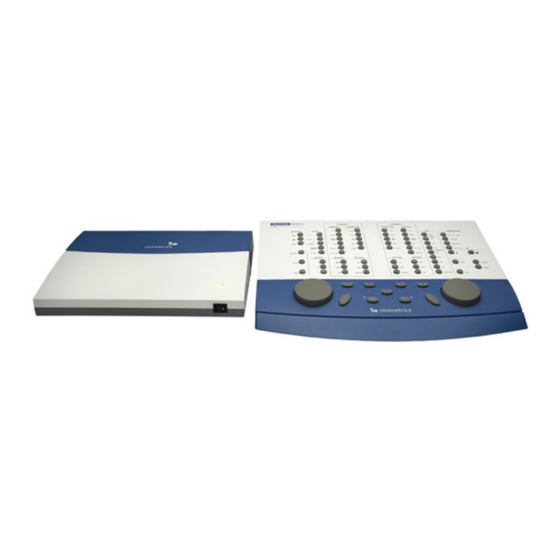
1 Device description Device description Madsen® Astera² is a PC-controlled audiometer for testing a person's hearing.The audiometer is operated from the Oto- suite Audiometry Module PC software. With Madsen® Astera² you can perform standard audiometric tests, tone and speech audiometry and special tests. •... -
Page 5: Unpacking
Note Indicates that you should take special notice. • To obtain a free printed copy of the user documentation, contact Natus Medical Denmark ApS (www.natus.com). Unpacking 1. Unpack the device carefully. When you unpack the device and accessories, keep the packing material in which they were delivered. If you need to send the device in for service, the original packing material will protect against damage during transport. - Page 6 4 Installation Remove the cable cover 1. To remove the cable cover from Madsen® Astera² press the releases on both sides of the cable cover, swing the cover up into vertical position and lift it off Madsen® Astera². 2. Lift off the cable cover. Connect accessories Connecting accessories to Madsen®...
- Page 7 4 Installation Connecting Madsen® Astera² to Otosuite Tools • Run the Otosuite Configuration Wizard to connect to and set up communication with Madsen® Astera²: Select > Configuration Wizard (Tools > Configuration Wizard) Connecting the ACP to Madsen® Astera² Note Install Otosuite on the PC before you connect Madsen® Astera² to the PC. •...
- Page 8 4 Installation Speaker, built into the ACP Operator monitor speaker • Connect the gray cable in the cable bundle from the socket in the MADSEN Astera² rear panel to the Operator monitor speaker socket in the ACP. 3. When you have connected the accessories, slide the cable cover onto Madsen® Astera² and click it into place. Connecting the ACP to the PC The ACP is powered from the PC through a USB connection.
- Page 9 4 Installation The following applies only when used with the specified power supply, XP Power, type PCM80PS24: The installation must be carried out in accordance with IEC 60601-1, UL 60601-1. The supplementary pro- visions on the reliability of electro-medical systems. Warning Any equipment connected with the device or used in the proximity of the patient must •...
- Page 10 4 Installation Connecting accessories to Madsen® Astera² Caution Install Otosuite on the PC before you connect Madsen® Astera² to the PC. • The following applies only when used with the specified power supply, XP Power, type PCM80PS24: The installation must be carried out in accordance with IEC 60601-1, UL 60601-1. The supplementary pro- visions on the reliability of electro-medical systems.
- Page 11 P. Sound field speakers (line output) Note Blue corresponds to Left and red corresponds to Right. • Note Use only the power supply provided by Natus. • Caution • When you connect other electrical equipment to Madsen® Astera², remember that equipment that does not comply with the same safety standards as Madsen®...
-
Page 12: Powering The Device
Madsen® Astera² is powered through an external power supply connected directly to the mains outlet. Switching on Madsen® Astera² Use only the power supply provided by Natus. 1. Connect the mains plug of the external power supply directly to an AC mains outlet with a three-wire protective ground. -
Page 13: On-Screen Controls
7 On-screen controls On-screen controls Test controls provide a means of operating the audiometer if you use the mouse and on-screen options to perform tests. Tools Options Audiometry General On-screen controls Show • To enable test controls, select > > >... - Page 14 9 Toolbar icons in the Audiometry Module Audiometry icons Tone audiometry Speech audiometry Menu item Icon Description Combined Audiogram Click to toggle between viewing both ears in a single audiogram (com- (Combined Audiogram) bined audiogram) or both a left and a right audiogram on your screen. Combined View (Combined View) •...
-
Page 15: The Sunshine Panel
10 The Sunshine Panel Menu item Icon Description The options for frequency resolutions are 1/6, 1/12, 1/24 and 1/48 Frequency Resolution octave as well as 1 Hz. Select the different tone stimulus resolutions (Frequency Resolution) from the toolbar or from Tools >... - Page 16 10 The Sunshine Panel Tone testing Speech testing Use the Sunshine Panel to quickly select the main settings for testing. In the Sunshine Panel you can quickly select test ear, transducer, masking, and test type. Talk Forward You can control the monitor level, activate the (Talk For- Test Selector ward) dialog, and select the...
- Page 17 10 The Sunshine Panel Function Icon Description Stimulus Ear Selection Click to select test ear: (Stimulus Ear Selec- Right • (Right) tion) Binaural • (Binaural) Left • (Left) Transducer Selection Click to select the transducer used for the test ear: (Transducer Selection) •...
-
Page 18: Proper Transducer Placement
11 Proper transducer placement Function Icon Description Curve Selection (Curve Click to select the curve type: Selection) • (THR) (Threshold level) (Tone) • (MCL) (Most Comfortable Loudness level) • (UCL) (Uncomfortable Loudness level) • (SDT) (Speech Detection Threshold) (Speech) • (SRT) (Speech Recognition Threshold) (Speech) WRS/SRS •... - Page 19 11 Proper transducer placement 2. It is best to clip the insert earphone transducers behind the child or on the back of their clothing and then fit the foam eartip into the child's ears. Bone Conductor Note For unmasked bone thresholds, you can store binaural data: •...
-
Page 20: Performing Tone Audiometry
12 Performing tone audiometry Performing tone audiometry Sunshine Panel A. Ear selection B. Stimulus transducer C. Masking, transducer and On/Off D. Stimulus type Test type Talk Forward dialog G. Monitor/Level H. Test Selector Classic Control Panel A. Control Panel B. Test Options panel C. -
Page 21: Performing Speech Audiometry
13 Performing speech audiometry Store 7. Use the (Store) button (the S key on the keypad) to store the data point and proceed to the next frequency. 8. Repeat steps 4 to 7 until all the measurements you need have been completed. If needed, did you test: –... - Page 22 13 Performing speech audiometry Classic Control Panel A. Control Panel B. Test Options panel C. Monitor/Level panel Whenever the test buttons and other functions are used, you can use the corresponding keys on the keyboard, or the on- screen controls located at the top of the screen or in the Control Panel to the left. For detailed examples of audiometric testing, see the Madsen®...
- Page 23 13 Performing speech audiometry range 250 Hz to 4000 Hz. The headset microphone should be turned to a position just below the operator’s mouth. If an external playback device is used to generate speech stimuli via the line input of Madsen® Astera², only a high quality CD player or similar device should be used;...
-
Page 24: Maintenance
14 Maintenance If the patient is exposed to excessive levels of noise during the session, the system will interrupt the signal and display a warning. (1) Noise Exposure: Explanation of OSHA and NIOSH Safe.Exposure Limits and the Importance of Noise Dosimetry by Patricia A. -
Page 25: Other References
3. Insert the USB memory stick in an empty slot on your PC. 4. Call your Natus technical support team. They will use the application TeamViewer to ensure correct remote install- ation of the new calibration data on your system. -
Page 26: Technical Specifications
For Troubleshooting information, refer to the Madsen® Astera² Reference Manual. Technical specifications 16.1 Madsen® Astera² Type identification Madsen® Astera² is type 1066 from Natus Medical Denmark ApS. Channels Two separate and identical channels Frequency range TDH39 earphones: Standard frequencies: 125 Hz - 12500 Hz HDA 300 earphones: Standard frequencies: 125 Hz - 20000 Hz... - Page 27 16 Technical specifications Masking types • Narrow Band Noise Correlated – AC and BC Non-correlated – • Speech Weighted Noise Correlated – AC and BC Non-correlated – • White Noise (Wide band noise) Correlated – AC and BC Non-correlated – A.
- Page 28 16 Technical specifications Stimulus modulation FM (Warble): Adjustable modulation rate and depth • Modulation rate: 1Hz -20 Hz (default: 5 Hz). • Modulation depth: 1-25% of center frequency (default: 5%). SISI: 5, 2, 1 dB increments Accuracy of sound level Entire level range (AC): 125 Hz to 5000 Hz: ±3 dB 5000 Hz to 20000 Hz: ±5 dB...
- Page 29 16 Technical specifications Outputs 3 x 2 mono jacks, 1/4 " 2 x mono jacks, 1/4 " SF power output: 5 x terminals, Ω 5 x 40 W peak, 8 load SF line output: 3 x mini XLR 6 pin 5 x +6 dBu, balanced External inputs Ω...
- Page 30 16 Technical specifications Static force of transducer headbands TDH 39: 4.5 N ±0.5 N Bone vibrator: 5.4 N ±0.5 N HDA 300: 10 N USB interface Connector Type: USB Type B (Astera2), USB Type A (PC) Interface: USB 1.1 (compatible with USB 2.0, USB 3.0, USB 3.1 and USB 3.2 per www.USB.org) Transport and storage Temperature:...
- Page 31 16 Technical specifications Dimensions Approx. 325 x 255 x 60 mm (12.8 x 10 x 2.4 inches) Weight Approx. 1.3 kg (2.85 lb) Power supply External power supply, types: Delta Electronics, Inc. Output: 24 V DC, 3.75 A MDS-090AAS24 Input: 100-240 V AC, 50-60 Hz, 1.5 A - 0.75 A Patient Safety when used with the specified power supply, Delta Electronics, Inc., type MDS-090AAS24: •...
- Page 32 16 Technical specifications Standards Audiometer: EN 60645-1:2017 Type 1, Class B, IEC 60645-1:2017, and ANSI S3.6:2004 Patient Safety: Patient Safety when used with the specified power supply, Delta Electronics, Inc., type MDS-090AAS24: • Complies with ES60601-1:2005/(R)2012 and A1:2012 • CAN/CSA C22.2 NO 60601-1-14:2014 •...
- Page 33 16 Technical specifications Transport and storage Temperature: -30°C to +60°C (-22°F to 140°F) Air humidity: 10% to 90%, non-condensing Air pressure 50 kPa to 106 kPa Operating environment Mode of operation: Continuous Temperature: +15°C to +30°C (59°F to 95°F) Air humidity: 20% to 90%, non-condensing Air pressure 70 kPa to 106 kPa...
- Page 34 16 Technical specifications Standards Patient Safety: Complies with IEC 60601-1 Edition 3.1:2012, Class 1, Type B; UL 60601-1; CAN/CSA-C22.2 NO 60101.1-14. EMC: IEC 60601-1-2:2014, IEC 60601-1-2:2007, EN 60601-1-2:2015, and EN 60601-1- 2:2007 16.3 Accessories Standard accessories and optional accessories may vary from country to country - please consult your local distributor. Madsen®...
- Page 35 16 Technical specifications Group/Family Part number Accessory Details Miscellaneous 8-36-02319 XM-5000 SYS,RE OPTION Miscellaneous 49321077 Speaker Stand Headset/Speaker 8-75-69003 1066, MONITOR HEADSET Headset/Speaker 2-18-04200 Headset Monitoring Headset/Speaker 8-02-450 FF LOUDSPEAKER SET,C 115 Power Supply 5-01-11300 Power Supply Power Supply 5-01-10100 Power Supply, 24VDC, 80W Cables 8-71-79100 Cable USB (3m)
- Page 36 16 Technical specifications RF emissions Group 1 Madsen® Astera² uses RF energy only for its internal function. Therefore, its RF emissions are very CISPR11 low and are not likely to cause any interference in nearby electronic equipment. RF emissions Class A Madsen®...
- Page 37 16 Technical specifications Guidance and manufacturer's declaration - electromagnetic immunity - for equipment and systems within Professional Healthcare use environment Madsen® Astera² is intended for use in the electromagnetic environment specified below. The user of Madsen® Astera² should ensure that it is used in such an environment.
- Page 38 16 Technical specifications Rated maximum output power of Separation distance according to frequency of transmitter transmitter 150 kHz to 80 MHz 80 MHz to 800 MHz 800 MHz to 2.5 GHz d = 1.2 d = 1.2 d = 2.3 0.01 0.12 0.12...
- Page 39 16 Technical specifications Immunity test IEC 60601 Compliance level Electromagnetic environment - guidance test level Electrostatic discharge (ESD) +/- 6 kV contact +/- 6 kV contact Floors should be wood, concrete or ceramic tile. If floors are IEC 61000-4-2 +/- 8 kV air +/- 8 kV air covered with synthetic material, the relative humidity should be at least 30 %.
- Page 40 16 Technical specifications Conducted RF 3 V rms 3 V rms Portable and mobile RF communications equip- IEC 61000-4-6 150 kHz to 80 MHz 150 kHz to 80 MHz ment should be used no closer to any part of Mad- sen®...
-
Page 41: Definition Of Symbols
17 Definition of symbols 0.01 0.12 0.12 0.23 0.38 0.38 0.73 For transmitters rated at a maximum output power not listed above, the recommended separation distance d in meters (m) can be estimated using the equa- tion applicable to the frequency of the transmitter, where is the maximum output power rating of the transmitter in watts (W) according to the transmitter manufacturer. - Page 42 17 Definition of symbols ISO 15223- Medical devices — Symbols to Date of man- Indicates the date when 1:2016 Refer- be used with medical device ufacture the medical device was ence no. labels, labelling and inform- manufactured. 5.1.3. (ISO ation to be supplied – Part 1: 7000-2497) General requirements.
- Page 43 17 Definition of symbols ISO 15223- Medical devices —Symbols to Humidity lim- Indicates the range of 1:2016 Refer- be used with medical device itations (storage) humidity to ence no. labels, labelling and inform- which the medical device 5.3.8. (ISO ation to be supplied. can be safely exposed.
- Page 44 17 Definition of symbols IEC 60601-1, Medical electrical equipment General warning Indicates the need for the Table D.2 — Part 1: General require- sign user to consult the instruc- symbol 2 ments for basic safety and tions for use for important essential performance.
- Page 45 17 Definition of symbols Directive Waste Electrical and Elec- Disposal at end of Indicates that electrical 2012/19/EU tronic Equipment (WEEE) operating life and electronic waste instructions equipment waste should not be discarded together with unseparated waste but must be collected sep- arately. An indication of The product is a medical Medical device...
-
Page 46: Warnings, Cautions, And Notes
Directive 2012/19/EU. These regulations state that electrical and electronic waste must be separately collected for the proper treatment and recovery to ensure that WEEE is reused or recycled safely. In line with that commitment Natus may pass along the obligation for take back and recycling to the end user, unless other arrangements have been made. - Page 47 18 Warnings, Cautions, and Notes Fig. 1 Sockets with direct connections to patient transducers - Madsen® Astera² connection panel Isolated connectors • All connectors within the red frame are isolated from patient transducers. Note The safety standards listed in Technical specifications ►...
- Page 48 18 Warnings, Cautions, and Notes Warning The device should not be stacked with other equipment or placed in a poorly ventilated space as this • may affect the performance of the device. If it is stacked or placed adjacent to other equipment, make sure the oper- ation of the device is not affected.
- Page 49 18 Warnings, Cautions, and Notes Warning To comply with Medical Electrical Systems in IEC 60601-1 (Edition 3.1) computer and printer must be • placed at least 1.5 meters/5 ft away from the patient, so that the patient cannot reach the computer or printer. Warning Do not touch the patient at the same time you touch the output DC plug of the power supply or con- •...
- Page 50 18 Warnings, Cautions, and Notes 18.3 General cautions Caution Madsen® Astera² is intended for diagnostic and clinical use by audiologists, ENTs, and other trained • health care professionals in testing the hearing of their patients. Caution For the sake of safety and in order not to void the warranty, service and repair of electro-medical equip- •...
-
Page 51: Manufacturer
For safety reasons and due to effects on EMC, accessories connected to the equipment's outlet fittings must be • identical to the type supplied with the system. Manufacturer Natus Medical Denmark ApS Hoerskaetten 9, 2630 Taastrup Denmark +45 45 75 55 55 www.natus.com... - Page 52 19 Manufacturer The manufacturer reserves the right to disclaim all responsibility for the operating safety, reliability and performance of equipment serviced or repaired by other parties. Madsen® Astera²...
Need help?
Do you have a question about the Madsen Astera 2 and is the answer not in the manual?
Questions and answers