Table of Contents
Advertisement
Advertisement
Table of Contents

Related Manuals for Armstrong Medical AquaVENT FD140i


Summary of Contents for Armstrong Medical AquaVENT FD140i
- Page 1 Technical Manual AquaVENT FD140i ® Version: 1.0...
- Page 2 AquaVENT FD140i Technical Manual (v1.0) ®...
- Page 3 Table of Contents Table of Contents Introduction Guidelines for this technical manual 1.1.1 - Instructions for use 1.1.2 - Software and Hardware version 1.1.3 - Standard service procedures Symbols Abbreviations AquaVENT FD140i Overview ® General description AquaVENT FD140i features ® 2.2.1 - Safety features 2.2.2...
-
Page 4: Table Of Contents
Table of Contents 3.3.5 - Nebuliser set-up 3.3.6 - Touchscreen calibration Mechanical free-breathing valve test Post-service checkout Gas Flow Driver Safety Check sheet Device Troubleshooting Troubleshooting instructions Alarms 4.2.1 - Patient alarms 4.2.2 - Device alarms 4.2.3 - FiO 2 alarms Messages 4.3.1 - Messages during system test... - Page 5 Table of Contents 6.6.4 - Replacing flow sensor 6.6.5 - Replacing proportional valves 6.6.6 - Replacing pressure switches 6.6.7 - Replacing pressure regulators 6.6.8 - Replacing nebuliser valve 6.6.9 - Replacing gas inlet connectors 6.6.10 - Replacing o-rings at gas inlet connectors 6.6.11 - Replacing gas inlet filters 6.6.12...
- Page 6 This page is intentionally blank AquaVENT FD140i Technical Manual (v1.0) ®...
- Page 7 Introduction 1.0 Introduction AquaVENT FD140i Technical Manual (v1.0) ®...
- Page 8 Introduction 1.1 Guidelines for this technical manual This manual covers service information for the AquaVENT FD140i Gas Flow Driver ® Warning All service, repair and maintenance procedures as well as the setting of configuration and options may only be performed by an authorised service technician or a suitably qualified hospital engineer.
- Page 9 Introduction 1.1.3 Standard service procedures Normal operational tests, calibrations and troubleshooting can be performed on the AquaVENT FD140i without opening the system’s housing. Only repair and ® replacement procedures require opening the system’s housing. Warning After the AquaVENT FD140i has been serviced, the ‘Post-service Checkout’ ®...
- Page 10 Introduction 1.3 Abbreviations The following is a list of abbreviations used in this manual and device. Medical air Medical oxygen CPAP Continuous Positive Airway Pressure Positive Airway Pressure PEEP Positive End Expiratory Pressure FiO 2 Fraction of inspired oxygen Hardware version Software version Ser.- No.
- Page 11 AquaVENT FD140i Overview ® 2.0 AquaVENT FD140i Overview ® AquaVENT FD140i Technical Manual (v1.0) ®...
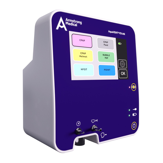
- Page 12 AquaVENT FD140i Overview ® 2.1 General description The AquaVENT FD140i is a gas fl ow driver that delivers an adjustable blend of medical ® air and oxygen to the patient via an attached breathing circuit. The device has six preset respiratory therapies: •...
- Page 13 AquaVENT FD140i Overview ® 2.2.2 Device layout Pressure measurement port Respiratory gas outlet Nebuliser port Touchscreen Alarm mute button Mains power connection indicator Battery status indicator Power ON/OFF button AquaVENT FD140i Technical Manual (v1.0) ®...
- Page 14 AquaVENT FD140i Overview ® 2.2.2 Device layout (cont’d) Refer to instruction manual Mains power inlet USB port AquaVENT FD140i Technical Manual (v1.0) ®...
- Page 15 AquaVENT FD140i Overview ® 2.2.2 Device layout (cont’d) Handle Fan outlet Fixation claw Serial plate Medical oxygen inlet (NIST) Medical air inlet (NIST) AquaVENT FD140i Technical Manual (v1.0) ®...
- Page 16 AquaVENT FD140i Overview ® 2.2.2 Device layout (cont’d) Over-pressure relief valve (do not obstruct) Mechanical under-pressure (free-breathing valve) (do not obstruct) AquaVENT FD140i Technical Manual (v1.0) ®...
- Page 17 AquaVENT FD140i Overview ® 2.2.3 Device interface and icons Front panel icons and indicator lights: Power source indicators AC mains power supply is connected when indicator light is illuminated Running on internal battery when indicator light is illuminated solid green Internal battery is charged when indicator light is flashing green Internal battery level is ≤...
- Page 18 AquaVENT FD140i Overview ® Power supply and battery charge indication Device unplugged from mains power Internal battery level - % charged (alternates between battery and unplugged icon) ...% Battery level at or below 20% remaining capacity Battery charging Charging General settings General settings menu Screen brightness Return to previous menu...
- Page 19 AquaVENT FD140i Overview ® 2.3 Pneumatic components This section will describe the components contained within the pneumatic assembly of the AquaVENT FD140i. ® All components are located on the pneumatic assembly, excluding the following components, which are components included in a breathing circuit: •...
- Page 20 AquaVENT FD140i Overview ® Proportional valve - AIR Proportional valve - O 2 Flow sensor - AIR Flow sensor - O 2 Flow mesh - AIR Flow mesh - O 2 Volume chamber Nebuliser valve Stenosis restrictor OS1/OS2 O 2 Concentration Sensor Free-breathing valve Over-pressure valve Patient Pressure sensor...
- Page 21 AquaVENT FD140i Overview ® O 2 flow PV2 is a proportional valve used to control the flow of O 2 in the system. The flow control mesh – O 2 (M2) is used to create a differential pressure from the flow and the O 2 flow sensor (S2) is used to measure this differential pressure.
- Page 22 AquaVENT FD140i Overview ® 2.4 Electrical components HW 1.01 - The following overview diagram illustrates all electrical components contained within the AquaVENT FD140i. ® The electrical components can be split into three groups based on their placement within the device: •...
- Page 23 AquaVENT FD140i Overview ® 2.4.1 Main board Microcontroller The microcontroller (MC1) deals with all inputs through the LCD touchscreen (LCD1), data provided by all sensors and controlling all pneumatic functions. It controls what information is displayed on the LCD touchscreen. It can send alerts in the form of an alarm through a speaker, touchscreen and LEDs.
- Page 24 AquaVENT FD140i Overview ® Paramagnetic The AquaVENT FD140i can be fitted with a paramagnetic O 2 sensor. ® O 2 sensor This continuously monitors the FiO 2. If this value is measured outside of specifications it will generate an alarm. Patient Pressure sensor (S3) transmits information to the microcontroller in Patient Pressure sensor...
- Page 25 AquaVENT FD140i Overview ® This page is intentionally blank AquaVENT FD140i Technical Manual (v1.0) ®...
- Page 26 This page is intentionally blank AquaVENT FD140i Technical Manual (v1.0) ®...
- Page 27 Calibration and Testing 3.0 Calibration and Testing AquaVENT FD140i Technical Manual (v1.0) ®...
- Page 28 Calibration and Testing 3.1 Calibration and Testing The AquaVENT FD140i software includes a self-test called ‘Self-Check’ that ® determines if the operating software, electronic circuits and pneumatic circuits are functioning properly. 3.1.1 Self-Check The Self-Check is started automatically when the device is turned on and takes approximately 10 seconds to complete.
- Page 29 Calibration and Testing If a malfunction is identified during Self-Check, the corresponding message appears on screen. Depending on the priority of the alarm, the message displayed will read either ‘Note’ , ‘Fault’ or ‘Critical Fault’ , as seen below. If ‘Note’ is displayed, it means that the device will still pass the Self-Check and will allow the user to start therapy.
- Page 30 Calibration and Testing If the user chooses ‘Yes’ , the paramagnetic oxygen sensor will go through an automatic calibration process, which lasts 75 seconds and then will go to the mode selection sreen. If the user chooses ‘No’ , the mode selection screen will appear. When the mode selection screen is displayed, there is a choice between six diff erent therapy modes:...
- Page 31 Calibration and Testing 3.2 Service mode The service mode is used to test or troubleshoot the major components of the AquaVENT FD140i. For safety reasons, the service mode is not accessible ® during standby or in therapy mode. To enter the service mode, press/hold the following keys: •...
- Page 32 Calibration and Testing 3.2.1 Service mode pages The system will access the service mode. There are 2 pages in the service mode. Service mode - Page 1, Engineering I/O - turn device off UI - return to User Interface (Self-Check will run) Current Time and Date Current Battery status Patient Pressure graph...
- Page 33 Calibration and Testing Service mode - Page 2, Calibration UI - return to Engineering service mode page Flow O 2 - buttons to capture analog to digital conversion at each set O 2 flow point Flow AIR - buttons to capture analog to digital conversion at each set AIR flow point O 2 Conc.
- Page 34 Calibration and Testing This page is intentionally blank AquaVENT FD140i Technical Manual (v1.0) ®...
- Page 35 Calibration and Testing 3.3 Calibrations General Always allow the AquaVENT FD140i to warm up for at least 15 minutes ® instructions prior to any calibration procedure. The optimal room temperature to conduct calibration is approximately 23ºC. The following components of the AquaVENT FD140i may be calibrated during service: ®...
- Page 36 Calibration and Testing Test equipment specifications: External flow measurement device: • Pressure range: 0 - 160 L/min • Accuracy: ± 0.05 L/min or 2% of reading • Calibrated for: AIR and O 2 External pressure measurement device: • Pressure range: 0 - 100 hPa •...
- Page 37 Calibration and Testing This calibration can also be carried out manually. Follow instructions from 3.2 Service Mode to enter the Calibration Page, then: 1. Allow AIR to flow through the system for approximately 30 seconds by using the slider bar/buttons to open the valve for AIR. The O 2 bar must remain set to 0.
- Page 38 Calibration and Testing 3.3.3 O flow calibration 1. Connect the inspiratory port and external flow measurement device using a 22mm tube. 2. Ensure the external flow measurement device has been positioned so that gas will flow through in the correct direction (arrows should indicate the direction of flow on an external flow measurement device).
-
Page 39: Nebuliser Set-Up
Calibration and Testing 3.3.5 Nebuliser set-up The nebuliser value can only be set if the AquaVENT FD140i is connected through ® USB interface to a terminal program. The fl ow of the nebuliser does not have a default value. The fl ow rate of the nebuliser depends upon the restrictor employed in the manifold. -
Page 40: Mechanical Free-Breathing Valve Test
Calibration and Testing 3.4 Mechanical free-breathing valve test In the instance of a total gas supply failure, the AquaVENT FD140i can enable a ® spontaneously breathing patient to breathe ambient air. If a total gas supply failure occurs, the free-breathing valve (mechanical under-pressure valve) allows the inspiration of room air. - Page 41 Calibration and Testing AquaVENT FD140i Technical Manual (v1.0) ®...
- Page 42 Calibration and Testing This page is intentionally blank AquaVENT FD140i Technical Manual (v1.0) ®...
- Page 43 Troubleshooting 4.0 Troubleshooting AquaVENT FD140i Technical Manual (v1.0) ®...
-
Page 44: Troubleshooting Instructions
Troubleshooting 4.1 Troubleshooting instructions Warning A post-service checkout must be performed after any maintenance, service or repair has been carried out on the device. If not, patient injury could occur. For instructions on how to do so, refer to ‘3.5 Post-service checkout’. The AquaVENT FD140i software includes a self-test called ‘Self check’... -
Page 45: Alarms
Troubleshooting 4.2 Alarms The AquaVENT FD140i has a system in place ® that will alert the operator to issues, which have been divided into two priority groups: Low Priority Alarm High Priority Alarm (YELLOW) (RED) 4.2.1 Patient alarms Patient alarms are those which have been triggered by the patient's input to the system and will only occur during therapy. - Page 46 Troubleshooting Alarm Message Alarm Condition Action Inconsistent readings between Check the O 2 flow sensor cables. AIR pressure switch and O 2 flow If cables are as they should sensor. If O 2 supply is measured be, recalibrate the device. If Sensor O 2 defect when there should be no O 2 recalibration does not clear the...
-
Page 47: Messages
Troubleshooting 4.3 Messages 4.3.1 Messages during system test Alarm Message Alarm Condition Action Recalibrate device. If Oxygen 0 - 10 l/min recalibration does not clear Calibration O 2 Flow A calibration cannot be the alarm, return the device retrieved to the manufacturer Recalibrate device. - Page 48 Troubleshooting Alarm Message Alarm Condition Action Recalibrate device. If AIR 120 - 140 l/min calibration recalibration does not clear Calibration AIR Flow E cannot be retrieved the alarm, return the device to the manufacturer Recalibrate device. If Oxygen concentration recalibration does not clear Calibration O 2 Sensor sensor calibration cannot be the alarm, return the device...
- Page 49 Troubleshooting 4.3.2 Messages during O sensor calibration Alarm Message Alarm Condition Action Ensure both AIR and O 2 are supplied to Calibrate failure No O 2 or AIR supply device AquaVENT FD140i Technical Manual (v1.0) ®...
- Page 50 Troubleshooting This page is intentionally blank AquaVENT FD140i Technical Manual (v1.0) ®...
-
Page 51: Maintenance And Service
Maintenance and Service 5.0 Maintenance and Service AquaVENT FD140i Technical Manual (v1.0) ®... -
Page 52: General Instructions
Recommended Conducted by Instructions service interval Replacement/Service of AEC0355 Every 6 months Armstrong Medical Oxygen sensor if it is used Check for depletion and requirement of Every year Armstrong Medical oxygen fuel cell, if present Replace Cone Filters in the NIST fittings... -
Page 53: Service Kits
Maintenance and Service Recommended Conducted by Instructions service interval Every 3 years Armstrong Medical Replace Real Time Clock battery Every 6 years Armstrong Medical Replace O 2 pressure regulator Every 6 years Armstrong Medical Replace AIR pressure regulator Replace x2 proportional (flow sensor) - Page 54 Maintenance and Service Order Number Description FD140i service kit, 6-years • Gas outlet connector tool AMFD140iSK6Y • Precision Regulator 0-4bar High Flow (x2) • Proportional valve 2/2 3mm orifice 24vDC FL (x2) • Technical manual EN FD140i service kit, 10-years •...
- Page 55 Maintenance and Service This page is intentionally blank AquaVENT FD140i Technical Manual (v1.0) ®...
- Page 56 Maintenance and Service This page is intentionally blank AquaVENT FD140i Technical Manual (v1.0) ®...
- Page 57 Maintenance and Service This page is intentionally blank AquaVENT FD140i Technical Manual (v1.0) ®...
- Page 58 Maintenance and Service This page is intentionally blank AquaVENT FD140i Technical Manual (v1.0) ®...
-
Page 59: Repair Procedures
Repair Procedures 6.0 Repair Procedures AquaVENT FD140i Technical Manual (v1.0) ®... -
Page 60: General Instructions
Repair Procedures 6.1 General instructions Warning Post-service checkout is required after you complete this chapter. You always have to carry out a post-service checkout after performing any maintenance, service or repair. Failure to do so may result in patient injury. For details, refer to 3.5 Post-service checkout. -
Page 61: Opening The Device
Repair Procedures 6.3 Opening the device 6.3.1 Opening the housing To open the housing of the AquaVENT FD140i, follow this procedure: ® 1. Switch off the system 2. Disconnect the AC line supply (power supply) 3. Disconnect the gas supply 4. -
Page 62: Removing The Pneumatic Assembly
Repair Procedures 6.3.2 Removing the pneumatic assembly To remove the pneumatic assembly of the AquaVENT FD140i, follow this procedure: ® 1. Open the housing as described in 6.3.1 2. Remove the nebuliser port and patient pressure port from front of housing, and remove the gas outlet from underside of housing. -
Page 63: Device Assemblies
Repair Procedures 6.3.3 Device assemblies The following are located in the housing of the AquaVENT FD140i: ® 1. Display PCB 2. Battery 3. Exhaust fan and speaker 4. Power entry connector 5. Power supply unit 6. USB interface (USB port) AquaVENT FD140i Technical Manual (v1.0) ®... - Page 64 Repair Procedures The following components are located on the pneumatic assembly: 1. Pneumatic assembly circuit board 2. Paramagnetic O 2 sensor 3. Tube, nebuliser, pressure measurement connectors 4. Pressure switch (AIR) 5. Pressure regulator (AIR) 6. Proportional valve (AIR) 7. Proportional valve (O 2 ) 8.
-
Page 65: Software Update
To update the fi rmware, a bootloader application needs to be installed onto a Windows computer. Please contact Armstrong Medical for access to the bootloader application download fi le. Perform the following step to communicate to the AquaVENT FD140i via USB: ®... - Page 66 Repair Procedures Putting new fi rmware on the microprocessor of the AquaVENT FD140i : ® 1. Press the 'Fwm Cpy -> Old' button to copy the code on the microprocessor to the 'Last Code' location. This process wil take approximately 20-30 seconds. 2.
-
Page 67: Replacing Main Unit Components
Repair Procedures 6.5 Replacing main unit components Note To replace any main unit components, the housing must fi rst be opened. For instructions, refer to 6.3.1 Opening the housing. 6.5.1 Replacing battery 1. Follow instructions in 6.3.2 Removing the pneumatic assembly 2. -
Page 68: Replacing Lcd Screen
Repair Procedures 6.5.2 Replacing LCD screen Note In order to replace the LCD screen, the following must have already been successfully removed: • Pneumatic assembly (refer to 6.3.2) • Fan & Speaker assembly (refer to 6.5.5) • Power entry connector (refer to 6.5.6) •... -
Page 69: Replacing Display Pcb
Repair Procedures 6.5.3 Replacing display PCB Note In order to replace the display PCB, the following must have already been successfully removed: • Pneumatic assembly (refer to 6.3.2) • Fan & Speaker assembly (refer to 6.5.5) • Power entry connector (refer to 6.5.6) •... -
Page 70: Replacing Coin Cell
Repair Procedures 6.5.4 Replacing coin cell battery Note In order to replace the display PCB, the following must have already been successfully removed: • Pneumatic assembly (refer to 6.3.2) • Fan & Speaker assembly (refer to 6.5.5) • Power entry connector (refer to 6.5.6) •... -
Page 71: Replacing Alarm Loudspeaker
Repair Procedures 6.5.5 Replacing alarm loudspeaker Note In order to replace the alarm loudspeaker, the following must have already been successfully removed: • Pneumatic assembly (refer to 6.3.2) • Fan & Speaker assembly (refer to 6.5.5) 1. Remove the 6 screws from housing and place the replacement speaker into the speaker bracket, ensuring the speaker is oriented so that the cable sits in the cut-out of the bracket. -
Page 72: Replacing Fan Assembly
Repair Procedures 6.5.6 Replacing fan assembly Note In order to replace the fan assembly, the following must have already been successfully removed: • Pneumatic assembly (refer to 6.3.2) 1. Unplug the fan cable from connector J10 on display PCB. 2. Remove the 4 screws connecting the fan to the fan bracket using a Phillips screwdriver. -
Page 73: Replacing Power Entry Connector
Repair Procedures 6.5.7 Replacing power entry connector 1. Disconnect the live, neutral and protective earthing cables from the pins on the back of the power entry connector. 2. Using a Phillips screwdriver, remove the 2 screws holding the power entry connector in place and remove the power entry connector. -
Page 74: Replacing Power Supply Unit
Repair Procedures 6.5.8 Replacing power supply unit Note In order to replace the power supply unit, the following must have already been successfully removed: • Pneumatic assembly (refer to 6.3.2) 1. Disconnect the live/neutral cable and the power supply unit to Display PCB cable from power supply unit. -
Page 75: Replacing Usb Assembly
Repair Procedures 6.5.9 Replacing USB assembly 1. Disconnect the protective earth cable and 6-way Display PCB to USB PCB cable. 2. Using a picking tool, remove the USB port dust cover. 3. Using a Phillips screwdriver, remove the 2 screws holding the USB PCB in place. 4. -
Page 76: Replacing Pneumatic Assembly Components
Repair Procedures 6.6 Replacing pneumatic assembly components Caution After replacing any of the components contained within the pneumatic assembly, a full calibration must be performed on the device. Refer to Chapter 3 for instructions on calibration. 6.6.1 Replacing tube, nebuliser & patient pressure measurement connector The following steps are to replace the tube connector: 1. -
Page 77: Replacing Patient Pressure Sensor
Repair Procedures 6.6.3 Replacing patient pressure sensor Note In order to replace the patient pressure sensor, the following must have already been successfully removed: • Pneumatic assembly (refer to 6.3.2) 1. Disconnect patient pressure sensor cable from pneumatics PCB. 2. Remove the 2 screws to remove the sensor and block from the manifold. 3. -
Page 78: Replacing Flow Sensor
Repair Procedures 6.6.4 Replacing fl ow sensor Note In order to replace the fl ow sensor, the following must have already been successfully removed: • Pneumatic assembly (refer to 6.3.2) 1. Disconnect the appropriate sensor cable from pneumatics PCB, depending on which fl ow sensor requires replacement. -
Page 79: Replacing Proportional Valves
Repair Procedures 6.6.5 Replacing proportional valves Note In order to replace either proportional valve, the following must have already been successfully removed: • Pneumatic assembly (refer to 6.3.2) The following steps are to replace the AIR proportional valve (circled in red): 1. -
Page 80: Replacing Pressure Switches
Repair Procedures 6.6.6 Replacing pressure switches Note In order to replace the pressure switches, the following must have already been successfully removed: • Pneumatic assembly (refer to 6.3.2) 1. Remove the cable connecting the pressure switch to the pneumatics assembly circuit board from the PCB. -
Page 81: Replacing Pressure Regulators
Repair Procedures 6.6.7 Replacing pressure regulators Note In order to replace the pressure regulators, the following must have already been successfully removed: • Pneumatic assembly (refer to 6.3.2) 1. Using a 2mm Allen key, remove the two M3 screws of the regulator requiring replacement. -
Page 82: Replacing Nebuliser Valve
Repair Procedures 6.6.8 Replacing nebuliser valve Note In order to replace the nebuliser valve, the following must have already been successfully removed: • Pneumatic assembly (refer to 6.3.2) 1. Disconnect the cable from the nebuliser valve and remove the 2 screws holding it in place. -
Page 83: Replacing Gas Inlet Connectors
Repair Procedures 6.6.9 Replacing gas inlet connectors Note There are two gas inlet connectors on the AquaVENT FD140i, one for AIR and ® one for O2. To change these connectors the device housing does not need to be opened. 1. Use a 22mm wrench to disconnect the connectors from the manifold. -
Page 84: Replacing O-Rings At Gas Inlet Connectors
Repair Procedures 6.6.10 Replacing o-rings at gas inlet connectors 1. Remove the gas inlet connectors by following the instructions outline in Chapter 6.6.9. 2. Remove and replace the o-rings, ensuring they are positioned correctly as illustrated. AquaVENT FD140i Technical Manual (v1.0) ®... -
Page 85: Replacing Gas Inlet Filters
Repair Procedures 6.6.11 Replacing gas inlet filters 1. Remove the gas inlet connectors by following the instructions outlined in Chapter 6.5.9. 2. Remove the nylon cone filter from the inlet connector. 3. Place the new nylon cone filter into the connector as illustrated. 4. - Page 86 Repair Procedures 6.6.12 Replacing paramagnetic sensor Note In order to replace the paramagnetic O 2 sensor, the following must have already been successfully removed: • Pneumatic assembly (refer to 6.3.2) 1. Disconnect the cable which connects the paramagnetic oxygen sensor to the pneumatics assembly PCB from the sensor.
-
Page 87: Replacing Over Pressure Valve
Repair Procedures 6.6.13 Replacing over pressure valve Note In order to replace the over pressure valve, the following must have already been successfully removed: • Pneumatic assembly (refer to 6.3.2) 1. Remove the over pressure valve from the manifold using a 22mm socket, circled in red. -
Page 88: Replacing Mechanical Free-Breathing Valve
Repair Procedures 6.6.14 Replacing mechanical free-breathing valve Note In order to replace the mechanical free-breathing valve, the following must have already been successfully removed: • Pneumatic assembly (refer to 6.3.2) 1. Using a 2mm Allen key, remove the two screws at either side of the free breathing valve. -
Page 89: Replacing Fuel Cell
Repair Procedures 6.6.15 Replacing fuel cell Note In order to replace the fuel cell, the following must have already been successfully removed: • Pneumatic assembly (refer to 6.3.2) 1. Disconnect the cable which connects the fuel cell sensor to the pneumatics assembly PCB. - Page 90 Repair Procedures This page is intentionally blank AquaVENT FD140i Technical Manual (v1.0) ®...
- Page 91 Repair Procedures This page is intentionally blank AquaVENT FD140i Technical Manual (v1.0) ®...
- Page 92 Repair Procedures This page is intentionally blank AquaVENT FD140i Technical Manual (v1.0) ®...
-
Page 93: Illustrated Parts
Illustrated Parts 7.0 Illustrated Parts AquaVENT FD140i Technical Manual (v1.0) ®... -
Page 94: Service Tools
Illustrated Parts 7.1 Service tools Test equipment specifications: Flow measurement device: • Pressure range: 0 - 160 L/min • Accuracy: ± 0.05 L/min or 2% of reading • Calibrated for: AIR and O 2 Pressure measurement device: • Pressure range: 0 - 100 hPa •... - Page 95 Illustrated Parts AMFD140iSK2Y FD140i service kit, 2-years • Gas outlet connector tool • Sintered Bronze Disc 1" OD x 1/8"Thk 40 Micron • FD140i Rechargeable battery set • Cable No. 4 Battery-to-display / Control PCB • Technical manual EN AMFD140iSK3Y FD140i service kit, 3-years •...
-
Page 96: Main Unit Spare Parts
Illustrated Parts 7.2 Main unit spare parts Description Order Number FD140i Front casing set AMCOEM1000-001 (including membrane) (AMCOEM100-003) FD140i Rear casing set AMCOEM1000-002 FD140i Fan set AMCOEM1000-019 FD140i Speaker set AMCOEM1000-020 FD140i Rechargeable battery set AMCOEM1000-021 FD140i Display PCB(A) set for LCD screen AMCOEM1000-010 (including LCD screen) (AMCOEM1000-185) - Page 97 Illustrated Parts AquaVENT FD140i Technical Manual (v1.0) ®...
- Page 98 Illustrated Parts AquaVENT FD140i Technical Manual (v1.0) ®...
-
Page 99: Pneumatic Assembly Spare Parts
Illustrated Parts 7.3 Pneumatic assembly spare parts Note Most pneumatic spare part items described below consist of multiple order numbers; they are pre-assembled, but consist of multiple components. All order numbers must be included in each spare part order. Description Order Number Pressure regulator AMCOEM1000-111... - Page 100 Illustrated Parts Description Order Number AMCOEM1000-137 AIR inlet connector AMCOEM1000-132 AMCOEM1000-138 O2 inlet connect AMCOEM1000-132 Nylon cone fi lter for inlet connectors AMCOEM1000-133 AMCOEM1000-110 Free-breathing valve AMCOEM1000-158 AquaVENT FD140i Technical Manual (v1.0) ®...
- Page 101 Illustrated Parts AquaVENT FD140i Technical Manual (v1.0) ®...
- Page 102 Illustrated Parts AquaVENT FD140i Technical Manual (v1.0) ®...
- Page 103 Illustrated Parts This page is intentionally blank AquaVENT FD140i Technical Manual (v1.0) ®...
- Page 104 Illustrated Parts This page is intentionally blank AquaVENT FD140i Technical Manual (v1.0) ®...
-
Page 105: Appendices
Appendices 8.0 Appendices AquaVENT FD140i Technical Manual (v1.0) ®... - Page 106 Appendices 8.1 Display PCB connectors 1. Pneumatic assembly PCB 2. USB PCB 3. Power supply unit 4. Battery 5. Membrane 6. LCD screen - 4-way flexible PCB 7. LCD screen- multiway flexible PCB 8. Fan 9. Speaker AquaVENT FD140i Technical Manual (v1.0) ®...
- Page 107 Appendices 8.2 Pneumatics assembly PCB connectors 1. Thermistor (from air flow sensor) 2. Nebuliser valve 3. Paramagnetic oxygen sensor (if employed in device) 4. Air flow sensor 5. Patient pressure sensor 6. Oxygen flow sensor 7. Proportional valve (AIR) 8. Proportional valve (O 2 ) 9.
-
Page 108: Complete Spare Parts List
Appendices 8.3 Complete spare parts list Order number Description AMCOEM1000-004 FD140i PSU Insulation plate AMCOEM1000-022 FD140i Mounting bracket AMCOEM1000-023 FD140i Union connector cover plate AMCOEM1000-036 FD140i Patient pressure port AMCOEM1000-039 FD140i Patient circuit connector AMCOEM1000-107 FD140i Inlet Manifold AMCOEM1000-108 FD140i Control Manifold AMCOEM1000-109 Differential Pressure Sensor Manifold AMCOEM1000-113... - Page 109 Appendices AMCOEM1000-152 M5 External tooth washer AMCOEM1000-153 POSI pan head M5 x 10 St/St AMCOEM1000-154 Socket Head M3 x 5 St/St AMCOEM1000-156 Tab Terminal 45° stud mount 6.35 x 0.81mm AMCOEM1000-117 Ball 8mm St/St AMCOEM1000-118 Ball 11/64" St/St (440C) AMCOEM1000-119 Ball 3/32"...
- Page 110 Appendices 8.4 Revision history Ver. Date Description Author Approved by 20/10/2020 Initial release CA/CC AquaVENT FD140i Technical Manual (v1.0) ®...
- Page 111 Appendices This page is intentionally blank AquaVENT FD140i Technical Manual (v1.0) ®...
- Page 112 Appendices This page is intentionally blank AquaVENT FD140i Technical Manual (v1.0) ®...
- Page 113 Appendices This page is intentionally blank AquaVENT FD140i Technical Manual (v1.0) ®...
Need help?
Do you have a question about the AquaVENT FD140i and is the answer not in the manual?
Questions and answers